Predicting gas and shrinkage porosity in solidification microstructure: A coupled three-dimensional cellular automaton model
Cheng Gua, Colin D. Ridgewaya, Emre Cinkilica, Yan Lua, Alan A. Luo,a,*
a Department of Materials Science and Engineering, The Ohio State University, Columbus, OH 43210, USA
b Department of Integrated Systems Engineering, The Ohio State University, Columbus, OH 43210, USA
Corresponding authors:* Department of Materials Science and Engineering, TheOhio State University, Columbus, OH 43210, USA.E-mail address:luo. 445@osu.edu(A.A. Luo).
Porosity formation during solidification of aluminum-based alloys, due to hydrogen gas and alloy shrinkage, has been a major issue adversely affecting the performance of solidification products such as castings, welds or additively manufactured components. A three-dimensional cellular automaton (CA) model has been developed, for the first time, to couple the predictions of hydrogen-induced gas porosity and shrinkage porosity during solidification microstructure evolution of a binary Al-Si alloy. The CA simulation results are validated under various cooling rates by porosity measurements in an experimental wedge die casting using X-ray micro computed tomography (XMCT) technique. This validated porosity moel provides a critical link in integrated computation materials engineering (ICME) design and manufacturing of solidification products.
Cheng Gu, Colin D. Ridgeway, Emre Cinkilic, Yan Lu, Alan A. Luo. Predicting gas and shrinkage porosity in solidification microstructure: A coupled three-dimensional cellular automaton model. Journal of Materials Science & Technology[J], 2020, 49(0): 91-105 DOI:10.1016/j.jmst.2020.02.028
1. Introduction
The presence of porosity is a major defect observed in all solidification products including castings, welds and additively manufactured components. Porosity defects such as voids or pores within solidification products are known to reduce their mechanical and physical properties, in particular ultimate strength, elongation, as well as corrosion and fatigue and resistance. The formation of porosity defects observed in solidification products are induced by two mechanisms [1,2]: (1) shrinkage porosity due to the shrinkage of solidifying alloys and inadequate feeding during solidification, and (2) gas porosity due to air entrapment and/or insoluble gases such as hydrogen. The two kinds of porosity occur simultaneously often with different intensities, depending on specific solidification processing conditions. Understanding and accurate prediction of the formation and evolution of porosity defects is important for improving the quality and performance of solidification products as well as lowering production costs associated with scrap due to excessive porosity.
A great deal of experimental research has been performed on shrinkage porosity and/or gas porosity during solidification processing of aluminum alloys [[3], [4], [5]]. Magnusson and Arnberg [6] adopted an indirect Archimedian method to measure the density of liquid and solid hypoeutectic Al-Si alloys, and estimated that solidification shrinkage decreases with increasing Si content. Lee and Hunt [7] developed an X-ray Temperature Gradient Stage experimental technique to observe the porosity formation in situ during the directional solidification of an Al-Cu alloy. Based on extensive experimental observations, it is assumed that pores can be characterized according to their appearance on micrographs. Pores are classified as either shrinkage pore possess a tortuous shape surrounded by the tips of dendrites or gaseous pore with a circular or spherical morphology. This interpretation is generally but not necessarily correct [8], since most of porosity are influenced by both mechanisms, and whether the actual nucleation of pores has ever been observed remains unclear. Experiments have been performed to measure porosity directly after solidification, but it is difficult to understand the nucleation and evolution of both shrinkage and gas porosity during solidification. In addition, it is difficult to quantitatively distinguish shrinkage and gas porosity, or quantitatively predict the porosity for product design and process optimization. Modeling porosity formation has become a method to study and control porosity formation during solidification, which can be a critical link in integrated computational materials engineering [9,10] (ICME) implementation for solidification products.
Numerical methods have been used to investigate the mechanisms of porosity formation during solidification. It is known that the Niyama criterion [11] is one of the most widely used criteria to predict shrinkage porosity in metal casting. However, the Niyama criterion can only give a qualitative result based on local temperature gradient and cooling rate evaluated at a specified temperature near the end of solidification. Calson and Beckermann [12] later presented a dimensionless Niyama criterion to directly predict shrinkage porosity that forms during solidification of alloy castings. Although the dimensionless Niyama criterion can be used to quantitatively predict shrinkage porosity, the critical pressure drop which is necessary in the model cannot be provided and the prediction is not accurate since the microporosity cannot be predicted. Although the dimensionless Niyama criterion is able to predict a quantitative value for the porosity present, it is not able to distinguish the difference between gaseous porosity and shrinkage porosity. Meanwhile, current research on shrinkage porosity offers little perspective on the nucleation and growth of shrinkage porosity during solidification. To understand how to differentiate between these two types of pores, the formation mechanisms of each must be examined further. The formation of gas porosity, such as hydrogen gas pores in Al castings, has been studied analytically and numerically [[13], [14], [15]]. Yousefian and Tiryakioğlu [8] presented an discussion on experimental observations, modeling assumptions, and classical nucleation theory of pore formation during solidification of Al. Jie et al. [16,17] developed a mathematical model on the microporosity of Al castings, in which the pressure increase induced by dissolved hydrogen, solidification shrinkage and interface energy are considered. Most of the related research has focused on either shrinkage porosity or gas porosity [18], and there is little research considering both the effects of shrinkage and gas. It is important and necessary to couple the predictions of shrinkage porosity and gas porosity during microstructure evolution of solidification products [19]. With this tool, the formation and evolution of microstructure including both dendrite and porosity can be calculated, providing a critical link between location-specific microstructure models and location-specific mechanical property predictions, which is an essential part of ICME framework for solidification products.
In this paper, a three-dimensional (3-D) cellular automaton (CA) model was developed to simulate the formation and evolution of solidifying microstructure and microporosity. Both hydrogen-induced porosity and shrinkage porosity, as well as dendrite growth during solidification, were incorporated in the 3-D CA model as shown in Fig. 1. By applying the model, the evolution of solidifying dendrite and microporosity over time can be simulated simultaneously. The effects of different initial conditions such as cooling rates, shrinkage pressures, and initial hydrogen concentrations on porosity evolution were investigated and discussed. Wedge die casting experiments were performed and X-ray micro computed tomography (XMCT) measurements were conducted to compare with the 3-D CA simulated results as a validation.
Fig. 1.
Schematic diagram of dendrite growth and pore formation: (a) 2-D microstructure of dendrite and porosity; (b) optical micrograph of an Al-Si alloy; and (c) 3-D pore morphology by X-ray micro computed tomography.
2. Model description
2.1. Dendrite nucleation and growth
During the solidification process, the liquid-solid transformation occurs through the nucleation and the growth of solid grains/dendrites. The continuous nucleation distribution proposed by Rappaz [20,21] was adopted and extended [22] as:
where δn is the increment of nucleation density, Nmax is the maximum nucleation density, ΔTσ is the standard deviation of the distribution, and ΔTN is the mean nucleation undercooling. In a discrete time step δt, temperature decreases δT and undercooling accordingly increases from ΔT to ΔT+δΔT. Thus,${{X}_{\text{upper}}}=\frac{\Delta T+\delta (\Delta T)-\Delta {{T}_{N}}}{\sqrt{2}\Delta {{T}_{\sigma }}}$,${{X}_{\text{lower}}}=\frac{\Delta T-\Delta {{T}_{N}}}{\sqrt{2}\Delta {{T}_{\sigma }}}$,$\text{d}X=\frac{\text{d}(\Delta T')}{\sqrt{2}\Delta {{T}_{\sigma }}}$. Then the new nucleus number formed can be obtained:
$\delta N=\delta n{{V}_{C}}$
where δN is the nucleus number increment, which concretely represents the number of nucleus present in the calculation domain, and VC is the volume of the computational domain. The local undercooling ΔTE can be expressed as [[23], [24], [25], [26]]:
where $\frac{\partial T}{\partial C_{i}^{L}}$ is the liquidus slope with the solute element i, CiL is the local solute composition, Ci0 is the initial solute composition in the liquid. The local undercooling ΔTE instead of undercooling ΔT is used in Eq. (2), and thus the effect of solute on the undercooling could be considered. If only the total undercooling is considered, it is not possible to accurately achieve the location-specific nucleation phenomena and will result in an inaccurate final microstructure [22,27].
Following nucleation, dendrite growth must be accurately predicted. The S/L interface equilibrium and solute diffusion can be described as:
where ki is the solute partition coefficient of the solute element i, $ C_{i}^{S*}$ and $C_{i}^{L*}$ are the solute compositions at the S/L interface in solid and liquid respectively, $ C_{i}^{E}$ is the solute concentrations in phase E (superscript E represents S in solid or L in liquid), and D is the diffusion coefficient. Based on the interface thermodynamic equilibrium and the undercooling calculation, the solute composition at the S/L interface can be obtained as:
where ${{T}_{0}}\approx {{T}_{P}}-\frac{\partial T}{\partial C_{i}^{L}}C_{i}^{0}$ is the liquidus temperature at the initial solute concentration Ci0, TP is the liquidus temperature of pure aluminum, T* is the interface temperature, Γ is the Gibbs-Thomson coefficient, and κ is the curvature of the S/L interface which is obtained as 3-D weighted mean curvature [28]. Thus, based on the lever rule, the incremental solid fraction increase of the S/L interface can be calculated by:
According to the increase in solid fraction, the dendrite normal growth velocity, which can be described as the growth velocity directed from the solid toward the liquid, can be expressed as:
where Δx is the unit cell size, and ΔtC is time step. Nucleation and growth of dendrites during solidification can be obtained by solving Eq.s (1)-(9). It should be noted that the dendrite nucleation and growth model established here is for binary alloys. Further modeling details on ternary and multi-component system can be found in author’s previous publications [22,23,27].
2.2. Formation and evolution of porosity
As mentioned above, the formation and evolution of porosity is influenced by gas segregation and solidification shrinkage, which occurs simultaneously but with different intensities [29,30]. For gas porosity, hydrogen gas pores in aluminum are considered in this paper. As the solidification proceeds, hydrogen segregates into liquid due to the huge difference in solubility between the liquid and solid Al. However, the solubility of dissolved hydrogen in both liquid and solid decreases with the decreasing temperature during solidification. The results is a hydrogen concentration that is supersaturated in both phases, and forces the nucleation of pores heterogeneously on entrained oxide bifilms [31]. In this study, pore nucleation is assumed to occur only when the gas dissolved in the liquid exceeds the critical supersaturation. The stochastic porosity nucleation model [32] is adopted and can be expressed as:
where $N_{H}^{\text{max}}$ is the maximum pore nucleation density, $S_{H}^{\text{max}}$ and $S_{H}^{\text{min}}$ are the maximum and minimum porosity nucleation saturation respectively, $C_{H}^{L}$ and $S_{H}^{L}$ are the local hydrogen concentration (mL/100 g Al) and the local hydrogen saturation (mL/100 g Al) in liquid respectively, and $S_{H}^{N}$ is the critical saturation criterion for porosity nucleation. Atwood et al. [33,34] proposed an equation to determine the hydrogen solubility, and the hydrogen saturation within the melt can be obtained based on Sievert’s law as:
where PG is the internal pressure of a gas pore, P0 is the standard atmospheric pressure, and $C_{\text{Si}}^{L}$ is the solute concentrations of Si in melt Al. The effects of more elements on the hydrogen saturation in melt Al can be obtained in literatures [33,34]. It should be noted that the total driving force for the pore formation and evolution can be expressed by:
where Pm is the metallostatic pressure, ${{P}_{\sigma }}=2\gamma /{{r}_{P}}$ is the capillary pressure by liquid-gas surface tension, γ is the surface tension of the G/L interface, rP is the pore radius, and Ps is the shrinkage pressure. In this paper, shrinkage porosity is assumed only to be controlled by the change in shrinkage pressure. The effects of the metallostatic pressure is ignored in the following microstructure simulation. It assumes that once a pore has formed, a stable state is attained, and thus the pressure within the pore should be:
After the nucleation of a pore, the nucleated pore is able to absorb remaining supersaturated hydrogen, and start to grow under the effect of shrinkage pressure resulting from solidification shrinkage. Further, hydrogen atoms located in the liquid are able to be absorbed by adjacent pores. The diffusion of hydrogen can also be described in Eq. (6) and can be rewritten as:
where the right hand term $-\left( 1-{{f}_{S}}-{{f}_{G}} \right)\left( C_{H}^{L}-S_{H}^{L} \right)$ indicates that both G/L interface and G/L/S interface are considered, C and D now represent the hydrogen concentration and hydrogen diffusion coefficient, and kH is the partition coefficient of hydrogen. The solubility in the solid Al is determined based on the assumption that a constant partition coefficient of 0.069 was used for hydrogen [29,35]. The increased magnitude of hydrogen diffusion allows for hydrogen to diffuse and absorb into already nucleated pore and contributes to pore growth. According to the ideal gas law, the volume increment of a pore, ΔV, can be related to the hydrogen absorbed by all its interface cells, VG, and the pressure in the pore, PG:
where NG is the mole amount of hydrogen absorbed by all the interface cells which is the amount increment of hydrogen in the local region, R is the gas constant, Σ includes all G/L interface cells of the pore A (denoted pore A as an example), Vcell is the volume of a cell, and ρ is the density of liquid Al melt. Thus, the incremental volume increase can be calculated by considering geometrical factor GG [36]:
When fG equals to 1, the G/L interface cell transforms to a gas cell. The newly formed gas cell then captures all its liquid neighbor cells and transforms them to G/L interface cells. This process of pore evolution is then continued through the next time step. The time step for the solute diffusion and dendrite growth and for pore growth can be obtained based on the diffusion coefficient and cell space [36]. To increase the computational efficiency, two different time step are used in the calculation of dendrite growth and pore growth. Based on the model established above, both the hydrogen gas porosity and the shrinkage porosity are considered, and porosity evolution is able to be coupled with dendrite growth.
2.3. Cellular automaton method
A cellular automaton method is used to study the nucleation and growth of both pores and dendrites during solidification. CA is a discrete model with a set of rules for the cells to follow which was initially established in 2-D by von Neumann [37]. In order to obtain 3-D simulation, the 3-D calculation domain is divided into a uniform cubic arrangement of cells. Each cell is characterized by different variables of temperature, solute (Si in this study) concentration, hydrogen concentration, phase fraction (solid, liquid, and gas), and state. As the temperature drops and solidification begins, dendrites begin to nucleate and grow. Due to the phase equilibrium, solute (Si) is rejected from the solid, and accumulates at the S/L interface during liquid-solid transformation. Meanwhile, the excess atomic hydrogen is rejected from the solid into the remaining liquid phase, which, as noted, occurs due to minimal solubility of hydrogen in solid Al compared to liquid Al. As solidification proceeds, the hydrogen concentration in the remaining liquid continues to increase until a critical point is reached. When the atomic hydrogen reaches the solubility limit in the liquid, molecular hydrogen pores form in the gaseous state on entrained oxide bifilms. Based on the effect of the local hydrogen concentration levels and the local shrinkage pressure, the nucleated pores are able to grow or shrink. Assumptions adopted in the microstructure simulation are that the effect of fluid flow is not considered, and the eutectic solidification is not considered.
It is known that simulation of dendrite morphology using CA method usually lost its original crystallographic orientation [28,38,39,40,41]. The anisotropy from the regular 3-D coordinate system was adopted in this paper as described in authors’ previous study [42]. By using the method, simulation of dendrites with different preferred orientations can be achieved. Table 1 lists the input parameters used in the microstructure simulation.
Table 1
Table 1Input Parameters Used in the Microstructure Simulation.
The experiment was conducted using a commonly used cast alloy, aluminum A356. To investigate the effect of cooling rate on porosity formation, a V-shaped wedge casting was produced using a permanent mold to generate various cooling rates from the bottom tip to the top region. Fig. 2 presents the schematic geometry of the proposed wedge die casting in this study and the cast sample.
Fig. 2.
(a) Schematic of wedge die casting; (b) casting sample; and (c) a cross-section of the sample.
Primary A356 ingots were melted in an electric resistance furnace to about 973 K (700 °C) prior to pouring. Ingots were placed in a graphite crucible coated with boron nitride. As shown in Fig. 2, K-type thermocouples were placed at three different locations, and the corresponding temperature profiles were simultaneously measured during the casting process. The instantaneous cooling rates calculated directly at the liquidus temperature point of the three points are shown in Table 2.
Table 2
Table 2Instantaneous cooling rate (K/s) at different locations A, B and C.
The initial hydrogen concentration was measured by the reduced pressure test (RPT) [44,45], which has been widely used to check gas contents of molten Al alloys. Three samples were used in the test to get the average results. For each test, 100 g of A356 alloy was first melted in a muffle furnace at 973 K (700 °C). The average density of the sample was calculated based on Archimedes Principle. The hydrogen content $C_{H}^{0}$ (in mL/100 g Al) can be calculated as:
where P2 and T2 are reduced pressure (unit: mm Hg) and alloy solidus temperature (unit: K). In the present case, the average measured density was Drp = 2.26 g/cm3, and RPT pressure is P2 = 100 mm Hg. Meanwhile, for this common A356 alloy, its theoretical density is Dth = 2.68 g/cm3, and its solidus temperature is T2 = 830 K (557 °C). By plugging these numbers into Eq. (20) and Eq. (21), the hydrogen content can be calculated as $C_{H}^{0}$= 0.3 mL/100 g Al.
In addition, to characterize the porosity in the casting samples, X-ray micro computed tomography (XMCT) measurements were performed. Samples of different cooling rates were excised from three different locations in the wedge die casting. XMCT results were scanned at 90 kV, 80 μA and a resolution of 6.318 μm per voxel using HeliScanTM microCT. An exposure time of 0.11 s and a 2 mm-thick Al plate as a filter on detector were employed. For each scan, the morphology, volume, surface area and location of each pore were collected. The data were then reconstructed and analyzed using an image processing platform, ScanIP, in Simpleware software.
4. Results and discussion
4.1. Single pore growth simulation
To investigate whether the CA model established in this paper can be used to predict porosity, single pore growth was firstly simulated with a calculation domain of 200 × 200 × 200 μm3. Symmetrical boundary conditions were used on all of the six surfaces. The calculation domain was initially filled with Al-Si melt with an initial hydrogen concentration of 0.8 mL/100 g Al. The shrinkage pressure was 0.1 atm. A single pore was set at the center of calculation domain. Fig. 3 shows the simulation results of pore morphology and hydrogen concentration distribution at different time steps.
Fig. 3.
Evolutions of pore morphology and hydrogen concentration field with an initial hydrogen concentration of 0.8 mL/100 g Al and a shrinkage pressure of 0.1 atm at different time: (a) 0.05 s; (b) 0.1 s; (c) 0.15 s; and (d) 0.25 s.
Due to a high-level initial hydrogen concentration and the shrinkage pressure, the pore began to grow with time as shown in Fig. 3. It can be seen that, as the pore grows, hydrogen in the calculation domain will be gradually absorbed into a pore. The hydrogen concentration field clearly shows that the hydrogen concentration near the pore is lower than that away from the pore into the liquid. With the growth of the pore, the average hydrogen concentration in the calculation domain decreases. When the local hydrogen concentration is no longer higher than the local hydrogen saturation, the pore growth stops as shown in Fig. 3(d), which also shows that the hydrogen concentration in the remaining liquid is evenly distributed. The effect of different shrinkage pressures was examined next for the single pore growth as shown in Fig. 4.
Fig. 4.
Evolutions of pore morphology and hydrogen concentration field at 0.1 s with an initial hydrogen concentration of 0.8 mL/100 g Al and different shrinkage pressure of: (a) 0 atm; (b) 0.2 atm; (c) 0.5 atm; and (d) 1.0 atm.
When shrinkage pressure is increased from 0 atm to 1.0 atm, the pore radius increases with the other conditions remain constant. Fig. 4 also displays that the larger the pore, the lower the average hydrogen concentration will remain in the calculation domain. This occurs due to the larger pore will result in lower local hydrogen saturation and larger area of G/L interface, which will increase the hydrogen amount absorbing from surrounded liquid into the pore.
Fig. 5 shows the percentage of porosity as a function of time with different shrinkage pressures. The percentage of porosity was calculated by dividing the volume of the pore by the volume of the whole calculation domain. It was assumed that the single pore is already nucleated, so any change in the percentage of porosity with time represents the growth of the pore.
Fig. 5.
Percentage of porosity as a function of time with different shrinkage pressures.
It is clear that with increasing shrinkage pressure, the final percentage of porosity increases. It can be observed that when the shrinkage pressure is small (most of the results except Ps = 2.0 atm), the percentage of porosity increases slowly at first, and later the rate increases steadily before slowing toward an asymptotic level. It is important to note that the shrinkage pressure of 2.0 atm was set as an extreme large value [17] which will be illustrated in the following section. At the beginning of the pore growth, the local hydrogen concentration is just a little larger than local hydrogen saturation, which results in a small growth velocity of the pore. With the growth of the pore, the pore radius increases and the local hydrogen saturation decreases, but the area of the G/L interface increases. There is more hydrogen available to be absorbed from the surrounding area into the gas pore, which increases the growth velocity of the pore. When the local hydrogen concentration is not larger than the local hydrogen saturation, the pore stops growing at last. When the shrinkage pressure is 2.0 atm, the percentage of porosity continues increasing when the time is around 0.06 s and grows rapidly. This is considered as an unrealistic case and is included to represent the bounds of realistic shrinkage pressure. It is important to note that the growth of the pore in this study is related to both hydrogen concentration and shrinkage pressure. From the simulated results shown in Fig. 4, it is known the higher the shrinkage pressure, the larger the pore. In the meantime, the larger pore will result in more hydrogen amount absorbed into the pore. Based on the equilibrium assumption of Eq. (13), both the small surface tension and the large shrinkage pressure will lead to a small internal pressure of the pore. However, with increased shrinkage pressure, the internal pressure could be smaller than zero. At this time, the equilibrium assumption is no longer suitable for the growth of the pore. According to the driving force of the pore formation (Eq. (13)), when the right hand term is smaller than zero, the left hand term will be always larger than the right hand term which means the driving force will cause the pore to continue to grow. Thus, the pore will always grow to the whole calculation domain which will lead to the continuous increase in the percentage of porosity when the shrinkage pressure is 2 atm.
4.2. Simulation of porosity formation coupled with dendrite growth
In order to simulate microstructure evolution of simultaneous dendritic growth and pore formation during solidification, single dendrite growth coupled with single pore growth was simulated to examine the solute and hydrogen distribution between them. The temperature in the entire calculation domain was assumed to be homogeneous with a constant cooling rate 10 K/s, and the initial temperature was set as the liquidus temperature of Al-8.5 wt%Si binary alloy. The initial hydrogen concentration in the alloy melt was set as 0.85 mL/100 g Al. The shrinkage pressure was 1.0 atm. The single dendrite was set at the left center of the calculation domain, and the single pore was set at the right center. As the beginning of the simulation the temperature begins to drop and the dendrite starts to grow due to undercooling. Simultaneously the pore will also begin to grow due to hydrogen saturation and shrinkage pressure. Fig. 6 shows the simulated results of dendrite and pore morphologies, and Si and hydrogen concentration field.
Fig. 6.
Simulated results of single dendrite and single pore morphologies: (a) with the cross-section of Si concentration at Y = 100 μm, t = 0.2 s; (b) with the cross-section of Si concentration at Y = 100 μm, t = 0.5 s; (c) Si concentration distribution along the line A-A shown in Fig. 6(a); (d) with the cross-section of hydrogen concentration at Y = 100 μm, t = 0.2 s; (e) with the cross-section of hydrogen concentration at Y = 100 μm, t = 0.5 s; and (f) hydrogen concentration distribution along the line A-A shown in Fig. 6(a).
During the dendritic growth the primary dendrite morphology can be clearly observed. The cross-sections at Y = 100 μm are shown to illustrate the diffusion of the solute Si and hydrogen during solidification. A high solute concentration region near the S/L interface in the liquid as it is trapped in the interdendritic regions as shown in Fig. 6(c). In the gas pore region, the Si concentration is zero. Meanwhile, since the diffusion coefficient of hydrogen in liquid Al is much larger (about two orders) than that of solute Si, there is much less hydrogen segregation or build near the S/L interface at dendrite fronts and the hydrogen will be nearly evenly distributed throughout the liquid. Since the growth of the pore will absorb hydrogen, the local hydrogen concentration decreases around the pore. With the growth of the pore, more hydrogen in the calculation domain will be absorbed and it can be seen the average hydrogen concentration in the whole calculation domain decreases (Figs. 6(d) and (e)).
Fig. 6 also shows that the dendrite growth affects both Si and hydrogen concentration. The pore growth does not change Si concentration much, but influences the distribution of hydrogen. It is interested that as the temperature decreases, both the dendrite and the pore start to grow, and the Si concentration near S/L interface increases due to solute equilibrium, while the Si concentration near G/L interface remains the same as shown in Fig. 6(c). However, hydrogen concentration near both S/L interface and G/L interface decreases as represented by the arrows shown in Fig. 6(f). This is counter-intuitive as it is expected that the hydrogen is reject from the solid it will pile-up outside the dendrite front at the L/S interface similar to Silicon. However, owing to increased diffusion rate, the hydrogen rejected from the dendrite growth is not enough to make up the hydrogen absorbed by the pore growth. It is also the reason that hydrogen concentration in the solid decreases, while Si concentration in the solid increases.
From the results obtained in the simulation above, it is clear that the present 3-D CA model can be used to simulate the dendrite nucleation/growth as well as the simultaneous porosity nucleation/growth on a larger, more realistic scale. The first simulation was run with a calculation domain of 200 × 200 × 200 μm3 and a constant cooling rate of 50 K/s. The initial hydrogen concentration in the Al-8.5 wt%Si binary melt is set as 0.8 mL/100 g Al. The shrinkage pressure was 0.5 atm. Fig. 7 shows simulated results of dendrites and pores at different time. Dendrite morphologies, pore morphologies, solute Si concentration fields, and hydrogen concentration fields at different time are examined.
Fig. 7.
Simulated dendrite morphologies (a1, b1, c1, d1; dendrites are shown in color green), pore morphologies (a2, b2, c2, d2; pores are shown in color black), Si concentration field (a3, b3, c3, d3), and hydrogen concentration field (a4, b4, c4, d4) at different time and temperatures: (a) 0.2 s, 870 K (597 °C); (b) 0.3 s, 865 K (592 °C); (c) 0.4 s, 860 K (587 °C); (d) 0.6 s, 850 K (577 °C).
At the beginning of solidification, the local hydrogen concentration is smaller than hydrogen saturation in melt Al, and no pores are able to nucleate and instead the pre-pores are in an incubation state. Fig. 6(a1) and 6(a2) demonstrate this phenomenon as they show that no pores exist in the calculation domain during the incubation period. As solidification and dendrite growth continues, pores begin to nucleate around the 0.3 s as shown in Fig. 7(b). The nucleated pores grow spherically due to interfacial tension. Fig. 7(c2) and Fig. 7(d2) show that there is a distribution pore size where several pores have large radii, while the other pores show to be very small. It can be observed that the larger pores nucleate earlier than the smaller pores and suggests the larger size pores occur due to extended growth time. When examining the pressure of varying pores, the solubility $S_{H}^{L}$ of a large pore is lower than that of a small pore. As solidification continues, the dendrites and pores continue growing and the growth of pores is blocked by the dendrite morphology, leading to irregular shapes of the pores as shown in Fig. 7(d2).
The third column and the forth column shows the Si concentration field and H concentration field of cross-section X = 150 μm, respectively. With the nucleation and the growth of the dendrites, Si is rejected from the solid phase, and enlarged at the S/L interface. As shown in Fig. 7(b3), local Si concentration near the solid phase is 11.11 wt%, while local Si concentration far from solid in the liquid is 8.5 wt%. Fig. 7(c3) shows the dendrite growth continues increasing the Si concentration in the remaining liquid.
Hydrogen concentration in the melt continues increasing prior to pore nucleation as shown in Fig. 7(a4) and (b4). Hydrogen diffuses much faster and there is no obvious hydrogen enrichment near S/L interface compared to Si as shown in Fig. 6. With the nucleation and growth of the pores, hydrogen atoms near the pores are absorbed which will decrease the local hydrogen concentration in the liquid. Meanwhile, the growth of dendrites continues rejecting hydrogen from the solid. This is the reason that the local hydrogen concentration far from the pores is 0.901 mL/100 g Al, while the local hydrogen concentration near the pores is 0.843 mL/100 g Al as shown in Fig. 7(c4). It is found that the lowest hydrogen concentration in the remaining liquid as shown in Fig. 7(d4) is around 0.46 mL/100 g Al, which is much lower than the initial hydrogen concentration of 0.8 mL/100 g Al. This lower level of hydrogen occurs because the local hydrogen saturation magnitude drops due to the temperature drop and the pore growth.
4.3. Effect of initial conditions
Input parameters (material parameters, processing parameters, etc.) are shown to have great influences on the final results. In this paper, the effects of initial conditions, such as cooling rate, shrinkage pressure, and initial hydrogen concentration, on final porosity results were studied. It is known that cooling rate plays an important role in microstructural evolution during solidification. Variable cooling rates have been shown to lead to different dendrite arm spacing/grain size [22,23] and different porosity percentages [12,32]. Along with microstructural feature size, the cooling rate will also effect the time for hydrogen diffusion and shrinkage pressure. To test the effects, different cooling rates were adopted in the following simulation. Fig. 8 shows the simulated morphologies of porosity and dendrites, and hydrogen concentration when the temperature is decreased to the eutectic temperature point with various cooling rates of 50 K/s, 20 K/s and 5 K/s. The size of the calculation domain was 500 × 500 × 500 μm3. The initial hydrogen concentration is set as 0.55 mL/100 g Al. The shrinkage pressure was 0.5 atm. With the decrease in cooling rate, the total number of pores decreases, while the average pore size increases. Conversely, a higher cooling rate will result in increased nucleus, faster dendrite growth velocity, less time for dendrite growth, and thus a finer grain size or smaller secondary dendrite arm spacing. The increased number of solidified dendrites and complex dendrite morphology hinders the growth of the nucleated pores and the diffusion of hydrogen in the remaining liquid. The local enriched hydrogen concentration leads to an increase in the number pore nuclei as the melt has less time for pore growth and hydrogen diffusion, resulting in smaller pore radius and increased number of pores. With a higher cooling rate, less time for pore growth and hydrogen diffusion also results in that more hydrogen will be present in the remaining liquid compared to lower cooling rates as shown in Fig. 8(g)-(i). The excess hydrogen was assumed to stay in this part and eventually in eutectic region.
Fig. 8.
Simulated results of porosity morphology, dendrite morphology and hydrogen concentration with different cooling rates: (a, d) 50 K/s; (b, e) 20 K/s; and (c, f) 5 K/s.
Fig. 9 plots the percentage of porosity as a function of temperature with different cooling rates shown in Fig. 8. Each of the percentage of porosity shows a trend to increase from zero to a constant value first, followed by an exponential increase. To examine this trend further, each stage was examined. At the beginning of solidification, the porosity percentage of each curve remains zero. When the nucleation of pores occurs, the porosity percentage jumps from zero to a specific value as the plateau shown in Fig. 9. This incubation time which appears in both pore nucleation and in pore growth agrees well with literature [32]. It should be noted that the growth of the pores and the decrease of temperature will continue decreasing the hydrogen saturation, which results in all percentages of porosity continue to increase as the temperature decreases, even at the end of the solidification. This is different from the results shown in Fig. 5. For variable cooling rates, as the cooling rate decreases, the final percentage of porosity at the eutectic temperature increases, which agrees well with the analysis above. On the other hand, with a lower cooling rate, the incubation time of pore nucleation is longer and the incubation time of pore growth is shorter, which can also be explained by the time allowed for hydrogen diffusion.
Fig. 9.
Percentage of porosity as a function of temperature with different cooling rates of 50 K/s, 20 K/s, and 5 K/s.
The effect of different shrinkage pressure was also studied by simulating the evolution of dendrites and porosity. Aside from the simulated results with a shrinkage pressure of 0.5 atm as shown in Fig. 8(a), shrinkage pressures of 0, 1.0, and 1.5 atm were also examined as shown in Fig. 10. All the other simulation conditions are the same with those of Fig. 8(a). With the increase in shrinkage pressure, the pore radius increases. However, the number of the pores does not change significantly when the shrinkage pressure increases from 0 atm to 1.5 atm. This phenomenon agrees with the pore nucleation analysis in the report [8].
Fig. 10.
Simulated porosity with different shrinkage pressures: (a) 0 atm; (b) 1.0 atm; and (c) 1.5 atm.
Fig. 11 plots the porosity percentage as a function of temperature with different shrinkage pressures and different initial hydrogen concentrations. It is clear that the final porosity percentage increases with the increase of shrinkage pressure. It can be obtained that the change of the shrinkage pressure does not affect the nucleation of the pore.
Fig. 11.
Percentage of porosity as a function of time with (a) different shrinkage pressures of 0 atm, 0.5 atm, 1.0 atm, and 1.5 atm; (b) different initial hydrogen concentrations of 0.5 mL/100 g Al, 0.55 mL/100 g Al, and 0.6 mL/100 g Al.
In the results with different initial hydrogen concentrations, the final porosity percentage increases with increasing initial in hydrogen concentration. Pores begin to nucleate at a lower temperature with a lower initial hydrogen concentration. This phenomenon occurs because with a lower initial hydrogen concentration, there will be less hydrogen enrichment at the G/L interface and maintain a hydrogen concentration below the critical hydrogen concentration. With the increase of the initial hydrogen concentration, hydrogen atoms remain in liquid and accumulate at the G/L interface to a value which satisfies the critical value for nucleation.
4.4. Experimental validation
In the industrial cast products, porosity can be controlled by reducing the gas quantity in the melt, or optimizing the solidification conditions. In an individual casting, cooling rates vary considerably at different locations due to varying section thickness/cooling lines etc., so it will lead to varying porosity size, morphology, and distribution which will result in location-specific mechanical properties in casting. As discussed above, the formation of porosity is a resultant of gas segregation and solidification shrinkage, which means both initial hydrogen concentration and shrinkage pressure will affect the final porosity results. The shrinkage pressure, Ps, is important in the prediction of porosity, which is expressed based on the assumption of unidirectional solidification [17,30,46]:
where v=βR is the average fluid flow velocity, β is solidification shrinkage factor, R is solidification rate, μ is the viscosity of the melt, fl is the volume fraction of liquid, K is the permeability which can be obtained by using the Carman-Kozeny approximation [[47], [48], [49]]:
where λ2 is the secondary dendrite arm spacing. It is known that different cooling rate will lead to different secondary dendrite arm spacing and different liquid-solid transformation, and eventually lead to different shrinkage pressure. However, it is important to point out Eq. (22) and Eq. (23) are proposed based on analytical unidirectional solidification modelling, which cannot be used in other situations especially in present the wedge casting case. Further, the hydrogen concentration will also change during solidification as shown in the simulation result of Fig. 7. It should be noted, at the macroscale, initial hydrogen concentration and shrinkage pressure are location-specific parameters which are extremely difficult to obtain through experiment measurement. In this paper, the microscopic initial hydrogen concentration and shrinkage pressure were estimated based on the solid fraction of the whole solidifying domain. According to hydrogen conservation, the initial hydrogen concentration in the local region, $C_{H}^{L,0}$, can be obtained:
where $C_{H}^{0}$ and fs,w is the initial hydrogen concentration and the solid fraction of the whole solidifying domain, respectively. The initial hydrogen concentration in the Al melt of wedge casting experiment was 0.3 mL/100 g Al. To estimate the shrinkage pressure, the volume change, ΔVc,w, can be calculated by ignoring other volume contractions (pipe, caved surface, etc.):
where ρl and ρs are the density of the melt and the solid, respectively. V0,w is the volume of the whole solidifying domain. Meanwhile, for the remaining melt, it can be obtained:
Based on the equations above, the estimated values of initial hydrogen concentration and shrinkage pressure for location-specific microstructure simulation can be obtained. The initial hydrogen concentration and shrinkage pressure as a function of solid fraction is shown in Fig. 12.
Fig. 12.
Initial hydrogen concentration and shrinkage pressure as a function of macrocosmic solid fraction.
Simulations were performed for quantitative comparison with wedge die casting experiments in this study. The porosity information from wedge die casting experiments was obtained by XMCT measurements. Binary Al-7 wt.%Si was used as an approximate composition in the simulation to compare with A356 Al alloy in wedge casting experiment. The calculations were performed in a domain of a 1000 × 1000 × 1000 μm3, which is the same with the XMCT measurements of 1.0 × 1.0 × 1.0 mm3. The initial hydrogen content and shrinkage pressure were set based on the macrocosmic solid fraction of 15.54 %, 39.67 %, and 63.8 % from the highest cooling rate to the lowest cooling rate. The cooling rates in the simulations were set match those observed in the experiments.
The porosity morphology comparison between XMCT results and 3-D CA simulated results is shown in Fig. 13. It can be clearly observed that the growth of porosity is hindered by the dendrite morphology, which results in the irregular shape of the pore. In the XMCT results, with the decrease of cooling rate, the porosity appears to have a larger radius and a more rounded morphology. In the CA simulated results, porosity morphology at the end of solidification was extracted. As the cooling rate decreased, the pore radius increased as expected, and the pore number decreases. These trends of pore size and pore number vs. cooling rate are in good agreement with literature [33]. It can be seen that 3-D CA simulation can be used to predict and visualize the porosity morphology and dendrites qualitatively, and the simulated results agree well with the experimental results. Meanwhile, Fig. 14 shows the comparison between experiment results and simulation results. It can be seen the simulation results considering both hydrogen gas and shrinkage match well with the experiment results. And the relationship between porosity percentage, P, and cooling rate, Rc, can be summarized as:
Fig. 14.
Comparison of porosity percentage between experiment results and simulation results of hydrogen gas pore and coupled gas and shrinkage pore.
As analyzed above, the initial conditions (cooling rate, initial hydrogen concentration, shrinkage pressure, etc.) affect the final percentage of porosity. Research has shown that the average final pore radius decreases with increasing cooling rate [50]. However, it should be noted that the porosity size is not uniform across a constant cooling rate [36]. By considering both hydrogen porosity and shrinkage porosity, the final porosity percentages of 3-D CA simulated results shows good agreement with the experiment results. By applying the present model, the evolution of dendrites coupled with both hydrogen and shrinkage porosity can be predicted and simulated qualitatively and quantitatively. The prediction of the formation and evolution of pores will help optimize the casting design and manufacturing in the production.
5. Conclusions
A three-dimensional cellular automaton model was developed to simulate the formation and evolution of solidifying microstructure and microporosity. Both hydrogen porosity and shrinkage porosity, as well as dendrite growth during solidification of binary Al-Si alloy, were considered in the model. The established model was validated to be able to simulate pore growth under the effect of hydrogen and shrinkage pressure. The nucleation and evolution of pore with multi-dendrites growth over time can be simulated. Dendrite morphologies, pore morphologies, solute Si concentration fields, and hydrogen concentration fields at different times were obtained. With the nucleation and growth of the pores, hydrogen atoms near the pores are absorbed which will decrease the local hydrogen concentration. Meanwhile, the growth of dendrites continues rejecting hydrogen from the solid. As the local hydrogen saturation decreases due to the temperature decreasing and the pore growing, pores continue absorbing hydrogen.
The effects of different initial conditions such as cooling rates, shrinkage pressures, and initial hydrogen concentrations on porosity evolution were investigated. With the increase of shrinkage pressure, the pore radius increases. The change of the shrinkage pressure does not affect the nucleation of the pore. With a lower initial hydrogen concentration, the final porosity percentage decreases.
Simulated results were validated by comparing porosity results from XMCT measurements of the wedge die casting experiments with the simulated results. The microscopic initial hydrogen concentration and shrinkage pressure were estimated. Validation experiments confirmed that an increased cooling rates results in a decrease in the percentage of porosity. By considering both hydrogen porosity and shrinkage porosity, the final porosity percentages of CA simulated results agree well with the experiment results. The validated porosity model will provide a critical link in ICME design and manufacturing of castings products.
Acknowledgments
The authors would like to acknowledge the National Science Foundation for supporting this work (Award CMMI-1432688). Part of the work was also supported by Honda R&D Americas (Raymond, Ohio). The authors acknowledge the helpful discussions with Duane Detwiler and Keith Ripplinger of Honda. Simulation Innovation and Modeling Center (SIMCenter) at The Ohio State University (OSU) is also acknowledged for providing access to supercomputers for simulation and modeling.
AbstractA three-dimensional (3-D) sharp interface model is developed to simulate the solutal dendritic growth in the low Péclet number regime. The model adopts a previously proposed solutal equilibrium approach to calculate the evolution of the solid/liquid interface. To describe specific crystallographic orientations of 3-D dendritic growth, a weighted mean curvature algorithm incorporated with the anisotropy of surface energy is proposed, allowing the simulation of 3-D dendrites with various orientations in a straightforward manner. The model validation is performed by comparing the simulations with the analytical predictions and experimental data for both single and multi-dendritic growth, which demonstrates the quantitative capabilities of the proposed model. The model efficiently reproduces realistic 3-D multi-equiaxed and columnar dendrites with various orientations and well-developed side branches.]]>
D.R.Poirier, K.Yeum, A.L.Maples, Metall. Trans. A18 (1987) 1979-1987.
Polycyclic aromatic compounds (PACs) are known due to their mutagenic activity. Among them, 2-nitrobenzanthrone (2-NBA) and 3-nitrobenzanthrone (3-NBA) are considered as two of the most potent mutagens found in atmospheric particles. In the present study 2-NBA, 3-NBA and selected PAHs and Nitro-PAHs were determined in fine particle samples (PM 2.5) collected in a bus station and an outdoor site. The fuel used by buses was a diesel-biodiesel (96:4) blend and light-duty vehicles run with any ethanol-to-gasoline proportion. The concentrations of 2-NBA and 3-NBA were, on average, under 14.8 microg g(-1) and 4.39 microg g(-1), respectively. In order to access the main sources and formation routes of these compounds, we performed ternary correlations and multivariate statistical analyses. The main sources for the studied compounds in the bus station were diesel/biodiesel exhaust followed by floor resuspension. In the coastal site, vehicular emission, photochemical formation and wood combustion were the main sources for 2-NBA and 3-NBA as well as the other PACs. Incremental lifetime cancer risk (ILCR) were calculated for both places, which presented low values, showing low cancer risk incidence although the ILCR values for the bus station were around 2.5 times higher than the ILCR from the coastal site.
J. VonNeumann,
Theory of Self-Reproducing Automata, Univeristy of Illinois
... The presence of porosity is a major defect observed in all solidification products including castings, welds and additively manufactured components. Porosity defects such as voids or pores within solidification products are known to reduce their mechanical and physical properties, in particular ultimate strength, elongation, as well as corrosion and fatigue and resistance. The formation of porosity defects observed in solidification products are induced by two mechanisms [1,2]: (1) shrinkage porosity due to the shrinkage of solidifying alloys and inadequate feeding during solidification, and (2) gas porosity due to air entrapment and/or insoluble gases such as hydrogen. The two kinds of porosity occur simultaneously often with different intensities, depending on specific solidification processing conditions. Understanding and accurate prediction of the formation and evolution of porosity defects is important for improving the quality and performance of solidification products as well as lowering production costs associated with scrap due to excessive porosity. ...
Rooy, Aluminum Alloy Castings: Properties, Processes, and Applications
1
2004
... The presence of porosity is a major defect observed in all solidification products including castings, welds and additively manufactured components. Porosity defects such as voids or pores within solidification products are known to reduce their mechanical and physical properties, in particular ultimate strength, elongation, as well as corrosion and fatigue and resistance. The formation of porosity defects observed in solidification products are induced by two mechanisms [1,2]: (1) shrinkage porosity due to the shrinkage of solidifying alloys and inadequate feeding during solidification, and (2) gas porosity due to air entrapment and/or insoluble gases such as hydrogen. The two kinds of porosity occur simultaneously often with different intensities, depending on specific solidification processing conditions. Understanding and accurate prediction of the formation and evolution of porosity defects is important for improving the quality and performance of solidification products as well as lowering production costs associated with scrap due to excessive porosity. ...
1
2010
... A great deal of experimental research has been performed on shrinkage porosity and/or gas porosity during solidification processing of aluminum alloys [[3], [4], [5]]. Magnusson and Arnberg [6] adopted an indirect Archimedian method to measure the density of liquid and solid hypoeutectic Al-Si alloys, and estimated that solidification shrinkage decreases with increasing Si content. Lee and Hunt [7] developed an X-ray Temperature Gradient Stage experimental technique to observe the porosity formation in situ during the directional solidification of an Al-Cu alloy. Based on extensive experimental observations, it is assumed that pores can be characterized according to their appearance on micrographs. Pores are classified as either shrinkage pore possess a tortuous shape surrounded by the tips of dendrites or gaseous pore with a circular or spherical morphology. This interpretation is generally but not necessarily correct [8], since most of porosity are influenced by both mechanisms, and whether the actual nucleation of pores has ever been observed remains unclear. Experiments have been performed to measure porosity directly after solidification, but it is difficult to understand the nucleation and evolution of both shrinkage and gas porosity during solidification. In addition, it is difficult to quantitatively distinguish shrinkage and gas porosity, or quantitatively predict the porosity for product design and process optimization. Modeling porosity formation has become a method to study and control porosity formation during solidification, which can be a critical link in integrated computational materials engineering [9,10] (ICME) implementation for solidification products. ...
1
2009
... A great deal of experimental research has been performed on shrinkage porosity and/or gas porosity during solidification processing of aluminum alloys [[3], [4], [5]]. Magnusson and Arnberg [6] adopted an indirect Archimedian method to measure the density of liquid and solid hypoeutectic Al-Si alloys, and estimated that solidification shrinkage decreases with increasing Si content. Lee and Hunt [7] developed an X-ray Temperature Gradient Stage experimental technique to observe the porosity formation in situ during the directional solidification of an Al-Cu alloy. Based on extensive experimental observations, it is assumed that pores can be characterized according to their appearance on micrographs. Pores are classified as either shrinkage pore possess a tortuous shape surrounded by the tips of dendrites or gaseous pore with a circular or spherical morphology. This interpretation is generally but not necessarily correct [8], since most of porosity are influenced by both mechanisms, and whether the actual nucleation of pores has ever been observed remains unclear. Experiments have been performed to measure porosity directly after solidification, but it is difficult to understand the nucleation and evolution of both shrinkage and gas porosity during solidification. In addition, it is difficult to quantitatively distinguish shrinkage and gas porosity, or quantitatively predict the porosity for product design and process optimization. Modeling porosity formation has become a method to study and control porosity formation during solidification, which can be a critical link in integrated computational materials engineering [9,10] (ICME) implementation for solidification products. ...
1
2015
... A great deal of experimental research has been performed on shrinkage porosity and/or gas porosity during solidification processing of aluminum alloys [[3], [4], [5]]. Magnusson and Arnberg [6] adopted an indirect Archimedian method to measure the density of liquid and solid hypoeutectic Al-Si alloys, and estimated that solidification shrinkage decreases with increasing Si content. Lee and Hunt [7] developed an X-ray Temperature Gradient Stage experimental technique to observe the porosity formation in situ during the directional solidification of an Al-Cu alloy. Based on extensive experimental observations, it is assumed that pores can be characterized according to their appearance on micrographs. Pores are classified as either shrinkage pore possess a tortuous shape surrounded by the tips of dendrites or gaseous pore with a circular or spherical morphology. This interpretation is generally but not necessarily correct [8], since most of porosity are influenced by both mechanisms, and whether the actual nucleation of pores has ever been observed remains unclear. Experiments have been performed to measure porosity directly after solidification, but it is difficult to understand the nucleation and evolution of both shrinkage and gas porosity during solidification. In addition, it is difficult to quantitatively distinguish shrinkage and gas porosity, or quantitatively predict the porosity for product design and process optimization. Modeling porosity formation has become a method to study and control porosity formation during solidification, which can be a critical link in integrated computational materials engineering [9,10] (ICME) implementation for solidification products. ...
1
2001
... A great deal of experimental research has been performed on shrinkage porosity and/or gas porosity during solidification processing of aluminum alloys [[3], [4], [5]]. Magnusson and Arnberg [6] adopted an indirect Archimedian method to measure the density of liquid and solid hypoeutectic Al-Si alloys, and estimated that solidification shrinkage decreases with increasing Si content. Lee and Hunt [7] developed an X-ray Temperature Gradient Stage experimental technique to observe the porosity formation in situ during the directional solidification of an Al-Cu alloy. Based on extensive experimental observations, it is assumed that pores can be characterized according to their appearance on micrographs. Pores are classified as either shrinkage pore possess a tortuous shape surrounded by the tips of dendrites or gaseous pore with a circular or spherical morphology. This interpretation is generally but not necessarily correct [8], since most of porosity are influenced by both mechanisms, and whether the actual nucleation of pores has ever been observed remains unclear. Experiments have been performed to measure porosity directly after solidification, but it is difficult to understand the nucleation and evolution of both shrinkage and gas porosity during solidification. In addition, it is difficult to quantitatively distinguish shrinkage and gas porosity, or quantitatively predict the porosity for product design and process optimization. Modeling porosity formation has become a method to study and control porosity formation during solidification, which can be a critical link in integrated computational materials engineering [9,10] (ICME) implementation for solidification products. ...
1
1997
... A great deal of experimental research has been performed on shrinkage porosity and/or gas porosity during solidification processing of aluminum alloys [[3], [4], [5]]. Magnusson and Arnberg [6] adopted an indirect Archimedian method to measure the density of liquid and solid hypoeutectic Al-Si alloys, and estimated that solidification shrinkage decreases with increasing Si content. Lee and Hunt [7] developed an X-ray Temperature Gradient Stage experimental technique to observe the porosity formation in situ during the directional solidification of an Al-Cu alloy. Based on extensive experimental observations, it is assumed that pores can be characterized according to their appearance on micrographs. Pores are classified as either shrinkage pore possess a tortuous shape surrounded by the tips of dendrites or gaseous pore with a circular or spherical morphology. This interpretation is generally but not necessarily correct [8], since most of porosity are influenced by both mechanisms, and whether the actual nucleation of pores has ever been observed remains unclear. Experiments have been performed to measure porosity directly after solidification, but it is difficult to understand the nucleation and evolution of both shrinkage and gas porosity during solidification. In addition, it is difficult to quantitatively distinguish shrinkage and gas porosity, or quantitatively predict the porosity for product design and process optimization. Modeling porosity formation has become a method to study and control porosity formation during solidification, which can be a critical link in integrated computational materials engineering [9,10] (ICME) implementation for solidification products. ...
3
2018
... A great deal of experimental research has been performed on shrinkage porosity and/or gas porosity during solidification processing of aluminum alloys [[3], [4], [5]]. Magnusson and Arnberg [6] adopted an indirect Archimedian method to measure the density of liquid and solid hypoeutectic Al-Si alloys, and estimated that solidification shrinkage decreases with increasing Si content. Lee and Hunt [7] developed an X-ray Temperature Gradient Stage experimental technique to observe the porosity formation in situ during the directional solidification of an Al-Cu alloy. Based on extensive experimental observations, it is assumed that pores can be characterized according to their appearance on micrographs. Pores are classified as either shrinkage pore possess a tortuous shape surrounded by the tips of dendrites or gaseous pore with a circular or spherical morphology. This interpretation is generally but not necessarily correct [8], since most of porosity are influenced by both mechanisms, and whether the actual nucleation of pores has ever been observed remains unclear. Experiments have been performed to measure porosity directly after solidification, but it is difficult to understand the nucleation and evolution of both shrinkage and gas porosity during solidification. In addition, it is difficult to quantitatively distinguish shrinkage and gas porosity, or quantitatively predict the porosity for product design and process optimization. Modeling porosity formation has become a method to study and control porosity formation during solidification, which can be a critical link in integrated computational materials engineering [9,10] (ICME) implementation for solidification products. ...
... Numerical methods have been used to investigate the mechanisms of porosity formation during solidification. It is known that the Niyama criterion [11] is one of the most widely used criteria to predict shrinkage porosity in metal casting. However, the Niyama criterion can only give a qualitative result based on local temperature gradient and cooling rate evaluated at a specified temperature near the end of solidification. Calson and Beckermann [12] later presented a dimensionless Niyama criterion to directly predict shrinkage porosity that forms during solidification of alloy castings. Although the dimensionless Niyama criterion can be used to quantitatively predict shrinkage porosity, the critical pressure drop which is necessary in the model cannot be provided and the prediction is not accurate since the microporosity cannot be predicted. Although the dimensionless Niyama criterion is able to predict a quantitative value for the porosity present, it is not able to distinguish the difference between gaseous porosity and shrinkage porosity. Meanwhile, current research on shrinkage porosity offers little perspective on the nucleation and growth of shrinkage porosity during solidification. To understand how to differentiate between these two types of pores, the formation mechanisms of each must be examined further. The formation of gas porosity, such as hydrogen gas pores in Al castings, has been studied analytically and numerically [[13], [14], [15]]. Yousefian and Tiryakioğlu [8] presented an discussion on experimental observations, modeling assumptions, and classical nucleation theory of pore formation during solidification of Al. Jie et al. [16,17] developed a mathematical model on the microporosity of Al castings, in which the pressure increase induced by dissolved hydrogen, solidification shrinkage and interface energy are considered. Most of the related research has focused on either shrinkage porosity or gas porosity [18], and there is little research considering both the effects of shrinkage and gas. It is important and necessary to couple the predictions of shrinkage porosity and gas porosity during microstructure evolution of solidification products [19]. With this tool, the formation and evolution of microstructure including both dendrite and porosity can be calculated, providing a critical link between location-specific microstructure models and location-specific mechanical property predictions, which is an essential part of ICME framework for solidification products. ...
... The effect of different shrinkage pressure was also studied by simulating the evolution of dendrites and porosity. Aside from the simulated results with a shrinkage pressure of 0.5 atm as shown in Fig. 8(a), shrinkage pressures of 0, 1.0, and 1.5 atm were also examined as shown in Fig. 10. All the other simulation conditions are the same with those of Fig. 8(a). With the increase in shrinkage pressure, the pore radius increases. However, the number of the pores does not change significantly when the shrinkage pressure increases from 0 atm to 1.5 atm. This phenomenon agrees with the pore nucleation analysis in the report [8]. ...
1
2011
... A great deal of experimental research has been performed on shrinkage porosity and/or gas porosity during solidification processing of aluminum alloys [[3], [4], [5]]. Magnusson and Arnberg [6] adopted an indirect Archimedian method to measure the density of liquid and solid hypoeutectic Al-Si alloys, and estimated that solidification shrinkage decreases with increasing Si content. Lee and Hunt [7] developed an X-ray Temperature Gradient Stage experimental technique to observe the porosity formation in situ during the directional solidification of an Al-Cu alloy. Based on extensive experimental observations, it is assumed that pores can be characterized according to their appearance on micrographs. Pores are classified as either shrinkage pore possess a tortuous shape surrounded by the tips of dendrites or gaseous pore with a circular or spherical morphology. This interpretation is generally but not necessarily correct [8], since most of porosity are influenced by both mechanisms, and whether the actual nucleation of pores has ever been observed remains unclear. Experiments have been performed to measure porosity directly after solidification, but it is difficult to understand the nucleation and evolution of both shrinkage and gas porosity during solidification. In addition, it is difficult to quantitatively distinguish shrinkage and gas porosity, or quantitatively predict the porosity for product design and process optimization. Modeling porosity formation has become a method to study and control porosity formation during solidification, which can be a critical link in integrated computational materials engineering [9,10] (ICME) implementation for solidification products. ...
1
2016
... A great deal of experimental research has been performed on shrinkage porosity and/or gas porosity during solidification processing of aluminum alloys [[3], [4], [5]]. Magnusson and Arnberg [6] adopted an indirect Archimedian method to measure the density of liquid and solid hypoeutectic Al-Si alloys, and estimated that solidification shrinkage decreases with increasing Si content. Lee and Hunt [7] developed an X-ray Temperature Gradient Stage experimental technique to observe the porosity formation in situ during the directional solidification of an Al-Cu alloy. Based on extensive experimental observations, it is assumed that pores can be characterized according to their appearance on micrographs. Pores are classified as either shrinkage pore possess a tortuous shape surrounded by the tips of dendrites or gaseous pore with a circular or spherical morphology. This interpretation is generally but not necessarily correct [8], since most of porosity are influenced by both mechanisms, and whether the actual nucleation of pores has ever been observed remains unclear. Experiments have been performed to measure porosity directly after solidification, but it is difficult to understand the nucleation and evolution of both shrinkage and gas porosity during solidification. In addition, it is difficult to quantitatively distinguish shrinkage and gas porosity, or quantitatively predict the porosity for product design and process optimization. Modeling porosity formation has become a method to study and control porosity formation during solidification, which can be a critical link in integrated computational materials engineering [9,10] (ICME) implementation for solidification products. ...
1
1982
... Numerical methods have been used to investigate the mechanisms of porosity formation during solidification. It is known that the Niyama criterion [11] is one of the most widely used criteria to predict shrinkage porosity in metal casting. However, the Niyama criterion can only give a qualitative result based on local temperature gradient and cooling rate evaluated at a specified temperature near the end of solidification. Calson and Beckermann [12] later presented a dimensionless Niyama criterion to directly predict shrinkage porosity that forms during solidification of alloy castings. Although the dimensionless Niyama criterion can be used to quantitatively predict shrinkage porosity, the critical pressure drop which is necessary in the model cannot be provided and the prediction is not accurate since the microporosity cannot be predicted. Although the dimensionless Niyama criterion is able to predict a quantitative value for the porosity present, it is not able to distinguish the difference between gaseous porosity and shrinkage porosity. Meanwhile, current research on shrinkage porosity offers little perspective on the nucleation and growth of shrinkage porosity during solidification. To understand how to differentiate between these two types of pores, the formation mechanisms of each must be examined further. The formation of gas porosity, such as hydrogen gas pores in Al castings, has been studied analytically and numerically [[13], [14], [15]]. Yousefian and Tiryakioğlu [8] presented an discussion on experimental observations, modeling assumptions, and classical nucleation theory of pore formation during solidification of Al. Jie et al. [16,17] developed a mathematical model on the microporosity of Al castings, in which the pressure increase induced by dissolved hydrogen, solidification shrinkage and interface energy are considered. Most of the related research has focused on either shrinkage porosity or gas porosity [18], and there is little research considering both the effects of shrinkage and gas. It is important and necessary to couple the predictions of shrinkage porosity and gas porosity during microstructure evolution of solidification products [19]. With this tool, the formation and evolution of microstructure including both dendrite and porosity can be calculated, providing a critical link between location-specific microstructure models and location-specific mechanical property predictions, which is an essential part of ICME framework for solidification products. ...
2
2009
... Numerical methods have been used to investigate the mechanisms of porosity formation during solidification. It is known that the Niyama criterion [11] is one of the most widely used criteria to predict shrinkage porosity in metal casting. However, the Niyama criterion can only give a qualitative result based on local temperature gradient and cooling rate evaluated at a specified temperature near the end of solidification. Calson and Beckermann [12] later presented a dimensionless Niyama criterion to directly predict shrinkage porosity that forms during solidification of alloy castings. Although the dimensionless Niyama criterion can be used to quantitatively predict shrinkage porosity, the critical pressure drop which is necessary in the model cannot be provided and the prediction is not accurate since the microporosity cannot be predicted. Although the dimensionless Niyama criterion is able to predict a quantitative value for the porosity present, it is not able to distinguish the difference between gaseous porosity and shrinkage porosity. Meanwhile, current research on shrinkage porosity offers little perspective on the nucleation and growth of shrinkage porosity during solidification. To understand how to differentiate between these two types of pores, the formation mechanisms of each must be examined further. The formation of gas porosity, such as hydrogen gas pores in Al castings, has been studied analytically and numerically [[13], [14], [15]]. Yousefian and Tiryakioğlu [8] presented an discussion on experimental observations, modeling assumptions, and classical nucleation theory of pore formation during solidification of Al. Jie et al. [16,17] developed a mathematical model on the microporosity of Al castings, in which the pressure increase induced by dissolved hydrogen, solidification shrinkage and interface energy are considered. Most of the related research has focused on either shrinkage porosity or gas porosity [18], and there is little research considering both the effects of shrinkage and gas. It is important and necessary to couple the predictions of shrinkage porosity and gas porosity during microstructure evolution of solidification products [19]. With this tool, the formation and evolution of microstructure including both dendrite and porosity can be calculated, providing a critical link between location-specific microstructure models and location-specific mechanical property predictions, which is an essential part of ICME framework for solidification products. ...
... Input parameters (material parameters, processing parameters, etc.) are shown to have great influences on the final results. In this paper, the effects of initial conditions, such as cooling rate, shrinkage pressure, and initial hydrogen concentration, on final porosity results were studied. It is known that cooling rate plays an important role in microstructural evolution during solidification. Variable cooling rates have been shown to lead to different dendrite arm spacing/grain size [22,23] and different porosity percentages [12,32]. Along with microstructural feature size, the cooling rate will also effect the time for hydrogen diffusion and shrinkage pressure. To test the effects, different cooling rates were adopted in the following simulation. Fig. 8 shows the simulated morphologies of porosity and dendrites, and hydrogen concentration when the temperature is decreased to the eutectic temperature point with various cooling rates of 50 K/s, 20 K/s and 5 K/s. The size of the calculation domain was 500 × 500 × 500 μm3. The initial hydrogen concentration is set as 0.55 mL/100 g Al. The shrinkage pressure was 0.5 atm. With the decrease in cooling rate, the total number of pores decreases, while the average pore size increases. Conversely, a higher cooling rate will result in increased nucleus, faster dendrite growth velocity, less time for dendrite growth, and thus a finer grain size or smaller secondary dendrite arm spacing. The increased number of solidified dendrites and complex dendrite morphology hinders the growth of the nucleated pores and the diffusion of hydrogen in the remaining liquid. The local enriched hydrogen concentration leads to an increase in the number pore nuclei as the melt has less time for pore growth and hydrogen diffusion, resulting in smaller pore radius and increased number of pores. With a higher cooling rate, less time for pore growth and hydrogen diffusion also results in that more hydrogen will be present in the remaining liquid compared to lower cooling rates as shown in Fig. 8(g)-(i). The excess hydrogen was assumed to stay in this part and eventually in eutectic region. ...
3
2004
... Numerical methods have been used to investigate the mechanisms of porosity formation during solidification. It is known that the Niyama criterion [11] is one of the most widely used criteria to predict shrinkage porosity in metal casting. However, the Niyama criterion can only give a qualitative result based on local temperature gradient and cooling rate evaluated at a specified temperature near the end of solidification. Calson and Beckermann [12] later presented a dimensionless Niyama criterion to directly predict shrinkage porosity that forms during solidification of alloy castings. Although the dimensionless Niyama criterion can be used to quantitatively predict shrinkage porosity, the critical pressure drop which is necessary in the model cannot be provided and the prediction is not accurate since the microporosity cannot be predicted. Although the dimensionless Niyama criterion is able to predict a quantitative value for the porosity present, it is not able to distinguish the difference between gaseous porosity and shrinkage porosity. Meanwhile, current research on shrinkage porosity offers little perspective on the nucleation and growth of shrinkage porosity during solidification. To understand how to differentiate between these two types of pores, the formation mechanisms of each must be examined further. The formation of gas porosity, such as hydrogen gas pores in Al castings, has been studied analytically and numerically [[13], [14], [15]]. Yousefian and Tiryakioğlu [8] presented an discussion on experimental observations, modeling assumptions, and classical nucleation theory of pore formation during solidification of Al. Jie et al. [16,17] developed a mathematical model on the microporosity of Al castings, in which the pressure increase induced by dissolved hydrogen, solidification shrinkage and interface energy are considered. Most of the related research has focused on either shrinkage porosity or gas porosity [18], and there is little research considering both the effects of shrinkage and gas. It is important and necessary to couple the predictions of shrinkage porosity and gas porosity during microstructure evolution of solidification products [19]. With this tool, the formation and evolution of microstructure including both dendrite and porosity can be calculated, providing a critical link between location-specific microstructure models and location-specific mechanical property predictions, which is an essential part of ICME framework for solidification products. ...
... Input Parameters Used in the Microstructure Simulation.
Parameter
Symbol
Units
Value
Ref.
Liquidus temperature of pure aluminum
TP
K
933.5
[43]
Liquidus slope of Si
$\frac{\partial T}{\partial C_{\text{Si}}^{L}}$
K/(mass)%
-6.6
[43]
Diffusion coefficient of Si in gradient Si in liquid
$D_{\text{Si}}^{L}$
m2/s
2.38E-9
[26]
Diffusion coefficient of Si in gradient Si in solid
$D_{\text{Si}}^{S}$
m2/s
1.30E-12
[26]
Partition coefficient of Si
kSi
\
0.117
[32]
Diffusion coefficient of H in liquid
$D_{H}^{L}$
m2/s
3.8E-9×exp(-2315/T)
[13]
Diffusion coefficient of H in solid
$D_{H}^{S}$
m2/s
1.1E-5×exp(-4922/T)
[13]
Average Gibbs-Thomson coefficient
Γ
m·K
1.7E-7
[32]
Maximum dendrite nucleation density
Nmax
m-3
1E12
\
Average nucleation undercooling
ΔTN
K
5.0
\
Deviation of nucleation undercooling
ΔTσ
K
0.5
\
Maximum pore nucleation density
$N_{H}^{\text{max}}$
m-3
1E9
\
Maximum pore nucleation saturation
$S_{H}^{\text{max}}$
mL/100 g Al
2.0
\
Minimum pore nucleation saturation
$S_{H}^{\text{min}}$
mL/100 g Al
1.4
\
Critical saturation criterion
$S_{H}^{N}$
\
1.2
\
Time step
t
s
1E-4
\
3. Wedge casting experiment and model validation
The experiment was conducted using a commonly used cast alloy, aluminum A356. To investigate the effect of cooling rate on porosity formation, a V-shaped wedge casting was produced using a permanent mold to generate various cooling rates from the bottom tip to the top region. Fig. 2 presents the schematic geometry of the proposed wedge die casting in this study and the cast sample. ...
... [13]
Average Gibbs-Thomson coefficient
Γ
m·K
1.7E-7
[32]
Maximum dendrite nucleation density
Nmax
m-3
1E12
\
Average nucleation undercooling
ΔTN
K
5.0
\
Deviation of nucleation undercooling
ΔTσ
K
0.5
\
Maximum pore nucleation density
$N_{H}^{\text{max}}$
m-3
1E9
\
Maximum pore nucleation saturation
$S_{H}^{\text{max}}$
mL/100 g Al
2.0
\
Minimum pore nucleation saturation
$S_{H}^{\text{min}}$
mL/100 g Al
1.4
\
Critical saturation criterion
$S_{H}^{N}$
\
1.2
\
Time step
t
s
1E-4
\
3. Wedge casting experiment and model validation
The experiment was conducted using a commonly used cast alloy, aluminum A356. To investigate the effect of cooling rate on porosity formation, a V-shaped wedge casting was produced using a permanent mold to generate various cooling rates from the bottom tip to the top region. Fig. 2 presents the schematic geometry of the proposed wedge die casting in this study and the cast sample. ...
1
2015
... Numerical methods have been used to investigate the mechanisms of porosity formation during solidification. It is known that the Niyama criterion [11] is one of the most widely used criteria to predict shrinkage porosity in metal casting. However, the Niyama criterion can only give a qualitative result based on local temperature gradient and cooling rate evaluated at a specified temperature near the end of solidification. Calson and Beckermann [12] later presented a dimensionless Niyama criterion to directly predict shrinkage porosity that forms during solidification of alloy castings. Although the dimensionless Niyama criterion can be used to quantitatively predict shrinkage porosity, the critical pressure drop which is necessary in the model cannot be provided and the prediction is not accurate since the microporosity cannot be predicted. Although the dimensionless Niyama criterion is able to predict a quantitative value for the porosity present, it is not able to distinguish the difference between gaseous porosity and shrinkage porosity. Meanwhile, current research on shrinkage porosity offers little perspective on the nucleation and growth of shrinkage porosity during solidification. To understand how to differentiate between these two types of pores, the formation mechanisms of each must be examined further. The formation of gas porosity, such as hydrogen gas pores in Al castings, has been studied analytically and numerically [[13], [14], [15]]. Yousefian and Tiryakioğlu [8] presented an discussion on experimental observations, modeling assumptions, and classical nucleation theory of pore formation during solidification of Al. Jie et al. [16,17] developed a mathematical model on the microporosity of Al castings, in which the pressure increase induced by dissolved hydrogen, solidification shrinkage and interface energy are considered. Most of the related research has focused on either shrinkage porosity or gas porosity [18], and there is little research considering both the effects of shrinkage and gas. It is important and necessary to couple the predictions of shrinkage porosity and gas porosity during microstructure evolution of solidification products [19]. With this tool, the formation and evolution of microstructure including both dendrite and porosity can be calculated, providing a critical link between location-specific microstructure models and location-specific mechanical property predictions, which is an essential part of ICME framework for solidification products. ...
1
2016
... Numerical methods have been used to investigate the mechanisms of porosity formation during solidification. It is known that the Niyama criterion [11] is one of the most widely used criteria to predict shrinkage porosity in metal casting. However, the Niyama criterion can only give a qualitative result based on local temperature gradient and cooling rate evaluated at a specified temperature near the end of solidification. Calson and Beckermann [12] later presented a dimensionless Niyama criterion to directly predict shrinkage porosity that forms during solidification of alloy castings. Although the dimensionless Niyama criterion can be used to quantitatively predict shrinkage porosity, the critical pressure drop which is necessary in the model cannot be provided and the prediction is not accurate since the microporosity cannot be predicted. Although the dimensionless Niyama criterion is able to predict a quantitative value for the porosity present, it is not able to distinguish the difference between gaseous porosity and shrinkage porosity. Meanwhile, current research on shrinkage porosity offers little perspective on the nucleation and growth of shrinkage porosity during solidification. To understand how to differentiate between these two types of pores, the formation mechanisms of each must be examined further. The formation of gas porosity, such as hydrogen gas pores in Al castings, has been studied analytically and numerically [[13], [14], [15]]. Yousefian and Tiryakioğlu [8] presented an discussion on experimental observations, modeling assumptions, and classical nucleation theory of pore formation during solidification of Al. Jie et al. [16,17] developed a mathematical model on the microporosity of Al castings, in which the pressure increase induced by dissolved hydrogen, solidification shrinkage and interface energy are considered. Most of the related research has focused on either shrinkage porosity or gas porosity [18], and there is little research considering both the effects of shrinkage and gas. It is important and necessary to couple the predictions of shrinkage porosity and gas porosity during microstructure evolution of solidification products [19]. With this tool, the formation and evolution of microstructure including both dendrite and porosity can be calculated, providing a critical link between location-specific microstructure models and location-specific mechanical property predictions, which is an essential part of ICME framework for solidification products. ...
1
2015
... Numerical methods have been used to investigate the mechanisms of porosity formation during solidification. It is known that the Niyama criterion [11] is one of the most widely used criteria to predict shrinkage porosity in metal casting. However, the Niyama criterion can only give a qualitative result based on local temperature gradient and cooling rate evaluated at a specified temperature near the end of solidification. Calson and Beckermann [12] later presented a dimensionless Niyama criterion to directly predict shrinkage porosity that forms during solidification of alloy castings. Although the dimensionless Niyama criterion can be used to quantitatively predict shrinkage porosity, the critical pressure drop which is necessary in the model cannot be provided and the prediction is not accurate since the microporosity cannot be predicted. Although the dimensionless Niyama criterion is able to predict a quantitative value for the porosity present, it is not able to distinguish the difference between gaseous porosity and shrinkage porosity. Meanwhile, current research on shrinkage porosity offers little perspective on the nucleation and growth of shrinkage porosity during solidification. To understand how to differentiate between these two types of pores, the formation mechanisms of each must be examined further. The formation of gas porosity, such as hydrogen gas pores in Al castings, has been studied analytically and numerically [[13], [14], [15]]. Yousefian and Tiryakioğlu [8] presented an discussion on experimental observations, modeling assumptions, and classical nucleation theory of pore formation during solidification of Al. Jie et al. [16,17] developed a mathematical model on the microporosity of Al castings, in which the pressure increase induced by dissolved hydrogen, solidification shrinkage and interface energy are considered. Most of the related research has focused on either shrinkage porosity or gas porosity [18], and there is little research considering both the effects of shrinkage and gas. It is important and necessary to couple the predictions of shrinkage porosity and gas porosity during microstructure evolution of solidification products [19]. With this tool, the formation and evolution of microstructure including both dendrite and porosity can be calculated, providing a critical link between location-specific microstructure models and location-specific mechanical property predictions, which is an essential part of ICME framework for solidification products. ...
3
2017
... Numerical methods have been used to investigate the mechanisms of porosity formation during solidification. It is known that the Niyama criterion [11] is one of the most widely used criteria to predict shrinkage porosity in metal casting. However, the Niyama criterion can only give a qualitative result based on local temperature gradient and cooling rate evaluated at a specified temperature near the end of solidification. Calson and Beckermann [12] later presented a dimensionless Niyama criterion to directly predict shrinkage porosity that forms during solidification of alloy castings. Although the dimensionless Niyama criterion can be used to quantitatively predict shrinkage porosity, the critical pressure drop which is necessary in the model cannot be provided and the prediction is not accurate since the microporosity cannot be predicted. Although the dimensionless Niyama criterion is able to predict a quantitative value for the porosity present, it is not able to distinguish the difference between gaseous porosity and shrinkage porosity. Meanwhile, current research on shrinkage porosity offers little perspective on the nucleation and growth of shrinkage porosity during solidification. To understand how to differentiate between these two types of pores, the formation mechanisms of each must be examined further. The formation of gas porosity, such as hydrogen gas pores in Al castings, has been studied analytically and numerically [[13], [14], [15]]. Yousefian and Tiryakioğlu [8] presented an discussion on experimental observations, modeling assumptions, and classical nucleation theory of pore formation during solidification of Al. Jie et al. [16,17] developed a mathematical model on the microporosity of Al castings, in which the pressure increase induced by dissolved hydrogen, solidification shrinkage and interface energy are considered. Most of the related research has focused on either shrinkage porosity or gas porosity [18], and there is little research considering both the effects of shrinkage and gas. It is important and necessary to couple the predictions of shrinkage porosity and gas porosity during microstructure evolution of solidification products [19]. With this tool, the formation and evolution of microstructure including both dendrite and porosity can be calculated, providing a critical link between location-specific microstructure models and location-specific mechanical property predictions, which is an essential part of ICME framework for solidification products. ...
... It is clear that with increasing shrinkage pressure, the final percentage of porosity increases. It can be observed that when the shrinkage pressure is small (most of the results except Ps = 2.0 atm), the percentage of porosity increases slowly at first, and later the rate increases steadily before slowing toward an asymptotic level. It is important to note that the shrinkage pressure of 2.0 atm was set as an extreme large value [17] which will be illustrated in the following section. At the beginning of the pore growth, the local hydrogen concentration is just a little larger than local hydrogen saturation, which results in a small growth velocity of the pore. With the growth of the pore, the pore radius increases and the local hydrogen saturation decreases, but the area of the G/L interface increases. There is more hydrogen available to be absorbed from the surrounding area into the gas pore, which increases the growth velocity of the pore. When the local hydrogen concentration is not larger than the local hydrogen saturation, the pore stops growing at last. When the shrinkage pressure is 2.0 atm, the percentage of porosity continues increasing when the time is around 0.06 s and grows rapidly. This is considered as an unrealistic case and is included to represent the bounds of realistic shrinkage pressure. It is important to note that the growth of the pore in this study is related to both hydrogen concentration and shrinkage pressure. From the simulated results shown in Fig. 4, it is known the higher the shrinkage pressure, the larger the pore. In the meantime, the larger pore will result in more hydrogen amount absorbed into the pore. Based on the equilibrium assumption of Eq. (13), both the small surface tension and the large shrinkage pressure will lead to a small internal pressure of the pore. However, with increased shrinkage pressure, the internal pressure could be smaller than zero. At this time, the equilibrium assumption is no longer suitable for the growth of the pore. According to the driving force of the pore formation (Eq. (13)), when the right hand term is smaller than zero, the left hand term will be always larger than the right hand term which means the driving force will cause the pore to continue to grow. Thus, the pore will always grow to the whole calculation domain which will lead to the continuous increase in the percentage of porosity when the shrinkage pressure is 2 atm. ...
... In the industrial cast products, porosity can be controlled by reducing the gas quantity in the melt, or optimizing the solidification conditions. In an individual casting, cooling rates vary considerably at different locations due to varying section thickness/cooling lines etc., so it will lead to varying porosity size, morphology, and distribution which will result in location-specific mechanical properties in casting. As discussed above, the formation of porosity is a resultant of gas segregation and solidification shrinkage, which means both initial hydrogen concentration and shrinkage pressure will affect the final porosity results. The shrinkage pressure, Ps, is important in the prediction of porosity, which is expressed based on the assumption of unidirectional solidification [17,30,46]: ...
1
2005
... Numerical methods have been used to investigate the mechanisms of porosity formation during solidification. It is known that the Niyama criterion [11] is one of the most widely used criteria to predict shrinkage porosity in metal casting. However, the Niyama criterion can only give a qualitative result based on local temperature gradient and cooling rate evaluated at a specified temperature near the end of solidification. Calson and Beckermann [12] later presented a dimensionless Niyama criterion to directly predict shrinkage porosity that forms during solidification of alloy castings. Although the dimensionless Niyama criterion can be used to quantitatively predict shrinkage porosity, the critical pressure drop which is necessary in the model cannot be provided and the prediction is not accurate since the microporosity cannot be predicted. Although the dimensionless Niyama criterion is able to predict a quantitative value for the porosity present, it is not able to distinguish the difference between gaseous porosity and shrinkage porosity. Meanwhile, current research on shrinkage porosity offers little perspective on the nucleation and growth of shrinkage porosity during solidification. To understand how to differentiate between these two types of pores, the formation mechanisms of each must be examined further. The formation of gas porosity, such as hydrogen gas pores in Al castings, has been studied analytically and numerically [[13], [14], [15]]. Yousefian and Tiryakioğlu [8] presented an discussion on experimental observations, modeling assumptions, and classical nucleation theory of pore formation during solidification of Al. Jie et al. [16,17] developed a mathematical model on the microporosity of Al castings, in which the pressure increase induced by dissolved hydrogen, solidification shrinkage and interface energy are considered. Most of the related research has focused on either shrinkage porosity or gas porosity [18], and there is little research considering both the effects of shrinkage and gas. It is important and necessary to couple the predictions of shrinkage porosity and gas porosity during microstructure evolution of solidification products [19]. With this tool, the formation and evolution of microstructure including both dendrite and porosity can be calculated, providing a critical link between location-specific microstructure models and location-specific mechanical property predictions, which is an essential part of ICME framework for solidification products. ...
1
2015
... Numerical methods have been used to investigate the mechanisms of porosity formation during solidification. It is known that the Niyama criterion [11] is one of the most widely used criteria to predict shrinkage porosity in metal casting. However, the Niyama criterion can only give a qualitative result based on local temperature gradient and cooling rate evaluated at a specified temperature near the end of solidification. Calson and Beckermann [12] later presented a dimensionless Niyama criterion to directly predict shrinkage porosity that forms during solidification of alloy castings. Although the dimensionless Niyama criterion can be used to quantitatively predict shrinkage porosity, the critical pressure drop which is necessary in the model cannot be provided and the prediction is not accurate since the microporosity cannot be predicted. Although the dimensionless Niyama criterion is able to predict a quantitative value for the porosity present, it is not able to distinguish the difference between gaseous porosity and shrinkage porosity. Meanwhile, current research on shrinkage porosity offers little perspective on the nucleation and growth of shrinkage porosity during solidification. To understand how to differentiate between these two types of pores, the formation mechanisms of each must be examined further. The formation of gas porosity, such as hydrogen gas pores in Al castings, has been studied analytically and numerically [[13], [14], [15]]. Yousefian and Tiryakioğlu [8] presented an discussion on experimental observations, modeling assumptions, and classical nucleation theory of pore formation during solidification of Al. Jie et al. [16,17] developed a mathematical model on the microporosity of Al castings, in which the pressure increase induced by dissolved hydrogen, solidification shrinkage and interface energy are considered. Most of the related research has focused on either shrinkage porosity or gas porosity [18], and there is little research considering both the effects of shrinkage and gas. It is important and necessary to couple the predictions of shrinkage porosity and gas porosity during microstructure evolution of solidification products [19]. With this tool, the formation and evolution of microstructure including both dendrite and porosity can be calculated, providing a critical link between location-specific microstructure models and location-specific mechanical property predictions, which is an essential part of ICME framework for solidification products. ...
1
1989
... During the solidification process, the liquid-solid transformation occurs through the nucleation and the growth of solid grains/dendrites. The continuous nucleation distribution proposed by Rappaz [20,21] was adopted and extended [22] as: ...
1
1993
... During the solidification process, the liquid-solid transformation occurs through the nucleation and the growth of solid grains/dendrites. The continuous nucleation distribution proposed by Rappaz [20,21] was adopted and extended [22] as: ...
4
2019
... During the solidification process, the liquid-solid transformation occurs through the nucleation and the growth of solid grains/dendrites. The continuous nucleation distribution proposed by Rappaz [20,21] was adopted and extended [22] as: ...
... where $\frac{\partial T}{\partial C_{i}^{L}}$ is the liquidus slope with the solute element i, CiL is the local solute composition, Ci0 is the initial solute composition in the liquid. The local undercooling ΔTE instead of undercooling ΔT is used in Eq. (2), and thus the effect of solute on the undercooling could be considered. If only the total undercooling is considered, it is not possible to accurately achieve the location-specific nucleation phenomena and will result in an inaccurate final microstructure [22,27]. ...
... where Δx is the unit cell size, and ΔtC is time step. Nucleation and growth of dendrites during solidification can be obtained by solving Eq.s (1)-(9). It should be noted that the dendrite nucleation and growth model established here is for binary alloys. Further modeling details on ternary and multi-component system can be found in author’s previous publications [22,23,27]. ...
... Input parameters (material parameters, processing parameters, etc.) are shown to have great influences on the final results. In this paper, the effects of initial conditions, such as cooling rate, shrinkage pressure, and initial hydrogen concentration, on final porosity results were studied. It is known that cooling rate plays an important role in microstructural evolution during solidification. Variable cooling rates have been shown to lead to different dendrite arm spacing/grain size [22,23] and different porosity percentages [12,32]. Along with microstructural feature size, the cooling rate will also effect the time for hydrogen diffusion and shrinkage pressure. To test the effects, different cooling rates were adopted in the following simulation. Fig. 8 shows the simulated morphologies of porosity and dendrites, and hydrogen concentration when the temperature is decreased to the eutectic temperature point with various cooling rates of 50 K/s, 20 K/s and 5 K/s. The size of the calculation domain was 500 × 500 × 500 μm3. The initial hydrogen concentration is set as 0.55 mL/100 g Al. The shrinkage pressure was 0.5 atm. With the decrease in cooling rate, the total number of pores decreases, while the average pore size increases. Conversely, a higher cooling rate will result in increased nucleus, faster dendrite growth velocity, less time for dendrite growth, and thus a finer grain size or smaller secondary dendrite arm spacing. The increased number of solidified dendrites and complex dendrite morphology hinders the growth of the nucleated pores and the diffusion of hydrogen in the remaining liquid. The local enriched hydrogen concentration leads to an increase in the number pore nuclei as the melt has less time for pore growth and hydrogen diffusion, resulting in smaller pore radius and increased number of pores. With a higher cooling rate, less time for pore growth and hydrogen diffusion also results in that more hydrogen will be present in the remaining liquid compared to lower cooling rates as shown in Fig. 8(g)-(i). The excess hydrogen was assumed to stay in this part and eventually in eutectic region. ...
3
2019
... where δN is the nucleus number increment, which concretely represents the number of nucleus present in the calculation domain, and VC is the volume of the computational domain. The local undercooling ΔTE can be expressed as [[23], [24], [25], [26]]: ...
... where Δx is the unit cell size, and ΔtC is time step. Nucleation and growth of dendrites during solidification can be obtained by solving Eq.s (1)-(9). It should be noted that the dendrite nucleation and growth model established here is for binary alloys. Further modeling details on ternary and multi-component system can be found in author’s previous publications [22,23,27]. ...
... Input parameters (material parameters, processing parameters, etc.) are shown to have great influences on the final results. In this paper, the effects of initial conditions, such as cooling rate, shrinkage pressure, and initial hydrogen concentration, on final porosity results were studied. It is known that cooling rate plays an important role in microstructural evolution during solidification. Variable cooling rates have been shown to lead to different dendrite arm spacing/grain size [22,23] and different porosity percentages [12,32]. Along with microstructural feature size, the cooling rate will also effect the time for hydrogen diffusion and shrinkage pressure. To test the effects, different cooling rates were adopted in the following simulation. Fig. 8 shows the simulated morphologies of porosity and dendrites, and hydrogen concentration when the temperature is decreased to the eutectic temperature point with various cooling rates of 50 K/s, 20 K/s and 5 K/s. The size of the calculation domain was 500 × 500 × 500 μm3. The initial hydrogen concentration is set as 0.55 mL/100 g Al. The shrinkage pressure was 0.5 atm. With the decrease in cooling rate, the total number of pores decreases, while the average pore size increases. Conversely, a higher cooling rate will result in increased nucleus, faster dendrite growth velocity, less time for dendrite growth, and thus a finer grain size or smaller secondary dendrite arm spacing. The increased number of solidified dendrites and complex dendrite morphology hinders the growth of the nucleated pores and the diffusion of hydrogen in the remaining liquid. The local enriched hydrogen concentration leads to an increase in the number pore nuclei as the melt has less time for pore growth and hydrogen diffusion, resulting in smaller pore radius and increased number of pores. With a higher cooling rate, less time for pore growth and hydrogen diffusion also results in that more hydrogen will be present in the remaining liquid compared to lower cooling rates as shown in Fig. 8(g)-(i). The excess hydrogen was assumed to stay in this part and eventually in eutectic region. ...
1
2015
... where δN is the nucleus number increment, which concretely represents the number of nucleus present in the calculation domain, and VC is the volume of the computational domain. The local undercooling ΔTE can be expressed as [[23], [24], [25], [26]]: ...
1
2013
... where δN is the nucleus number increment, which concretely represents the number of nucleus present in the calculation domain, and VC is the volume of the computational domain. The local undercooling ΔTE can be expressed as [[23], [24], [25], [26]]: ...
3
2015
... where δN is the nucleus number increment, which concretely represents the number of nucleus present in the calculation domain, and VC is the volume of the computational domain. The local undercooling ΔTE can be expressed as [[23], [24], [25], [26]]: ...
... Input Parameters Used in the Microstructure Simulation.
Parameter
Symbol
Units
Value
Ref.
Liquidus temperature of pure aluminum
TP
K
933.5
[43]
Liquidus slope of Si
$\frac{\partial T}{\partial C_{\text{Si}}^{L}}$
K/(mass)%
-6.6
[43]
Diffusion coefficient of Si in gradient Si in liquid
$D_{\text{Si}}^{L}$
m2/s
2.38E-9
[26]
Diffusion coefficient of Si in gradient Si in solid
$D_{\text{Si}}^{S}$
m2/s
1.30E-12
[26]
Partition coefficient of Si
kSi
\
0.117
[32]
Diffusion coefficient of H in liquid
$D_{H}^{L}$
m2/s
3.8E-9×exp(-2315/T)
[13]
Diffusion coefficient of H in solid
$D_{H}^{S}$
m2/s
1.1E-5×exp(-4922/T)
[13]
Average Gibbs-Thomson coefficient
Γ
m·K
1.7E-7
[32]
Maximum dendrite nucleation density
Nmax
m-3
1E12
\
Average nucleation undercooling
ΔTN
K
5.0
\
Deviation of nucleation undercooling
ΔTσ
K
0.5
\
Maximum pore nucleation density
$N_{H}^{\text{max}}$
m-3
1E9
\
Maximum pore nucleation saturation
$S_{H}^{\text{max}}$
mL/100 g Al
2.0
\
Minimum pore nucleation saturation
$S_{H}^{\text{min}}$
mL/100 g Al
1.4
\
Critical saturation criterion
$S_{H}^{N}$
\
1.2
\
Time step
t
s
1E-4
\
3. Wedge casting experiment and model validation
The experiment was conducted using a commonly used cast alloy, aluminum A356. To investigate the effect of cooling rate on porosity formation, a V-shaped wedge casting was produced using a permanent mold to generate various cooling rates from the bottom tip to the top region. Fig. 2 presents the schematic geometry of the proposed wedge die casting in this study and the cast sample. ...
... [26]
Partition coefficient of Si
kSi
\
0.117
[32]
Diffusion coefficient of H in liquid
$D_{H}^{L}$
m2/s
3.8E-9×exp(-2315/T)
[13]
Diffusion coefficient of H in solid
$D_{H}^{S}$
m2/s
1.1E-5×exp(-4922/T)
[13]
Average Gibbs-Thomson coefficient
Γ
m·K
1.7E-7
[32]
Maximum dendrite nucleation density
Nmax
m-3
1E12
\
Average nucleation undercooling
ΔTN
K
5.0
\
Deviation of nucleation undercooling
ΔTσ
K
0.5
\
Maximum pore nucleation density
$N_{H}^{\text{max}}$
m-3
1E9
\
Maximum pore nucleation saturation
$S_{H}^{\text{max}}$
mL/100 g Al
2.0
\
Minimum pore nucleation saturation
$S_{H}^{\text{min}}$
mL/100 g Al
1.4
\
Critical saturation criterion
$S_{H}^{N}$
\
1.2
\
Time step
t
s
1E-4
\
3. Wedge casting experiment and model validation
The experiment was conducted using a commonly used cast alloy, aluminum A356. To investigate the effect of cooling rate on porosity formation, a V-shaped wedge casting was produced using a permanent mold to generate various cooling rates from the bottom tip to the top region. Fig. 2 presents the schematic geometry of the proposed wedge die casting in this study and the cast sample. ...
2
2019
... where $\frac{\partial T}{\partial C_{i}^{L}}$ is the liquidus slope with the solute element i, CiL is the local solute composition, Ci0 is the initial solute composition in the liquid. The local undercooling ΔTE instead of undercooling ΔT is used in Eq. (2), and thus the effect of solute on the undercooling could be considered. If only the total undercooling is considered, it is not possible to accurately achieve the location-specific nucleation phenomena and will result in an inaccurate final microstructure [22,27]. ...
... where Δx is the unit cell size, and ΔtC is time step. Nucleation and growth of dendrites during solidification can be obtained by solving Eq.s (1)-(9). It should be noted that the dendrite nucleation and growth model established here is for binary alloys. Further modeling details on ternary and multi-component system can be found in author’s previous publications [22,23,27]. ...
2
2010
... where ${{T}_{0}}\approx {{T}_{P}}-\frac{\partial T}{\partial C_{i}^{L}}C_{i}^{0}$ is the liquidus temperature at the initial solute concentration Ci0, TP is the liquidus temperature of pure aluminum, T* is the interface temperature, Γ is the Gibbs-Thomson coefficient, and κ is the curvature of the S/L interface which is obtained as 3-D weighted mean curvature [28]. Thus, based on the lever rule, the incremental solid fraction increase of the S/L interface can be calculated by: ...
... It is known that simulation of dendrite morphology using CA method usually lost its original crystallographic orientation [28,38,39,40,41]. The anisotropy from the regular 3-D coordinate system was adopted in this paper as described in authors’ previous study [42]. By using the method, simulation of dendrites with different preferred orientations can be achieved. Table 1 lists the input parameters used in the microstructure simulation. ...
2
1987
... As mentioned above, the formation and evolution of porosity is influenced by gas segregation and solidification shrinkage, which occurs simultaneously but with different intensities [29,30]. For gas porosity, hydrogen gas pores in aluminum are considered in this paper. As the solidification proceeds, hydrogen segregates into liquid due to the huge difference in solubility between the liquid and solid Al. However, the solubility of dissolved hydrogen in both liquid and solid decreases with the decreasing temperature during solidification. The results is a hydrogen concentration that is supersaturated in both phases, and forces the nucleation of pores heterogeneously on entrained oxide bifilms [31]. In this study, pore nucleation is assumed to occur only when the gas dissolved in the liquid exceeds the critical supersaturation. The stochastic porosity nucleation model [32] is adopted and can be expressed as: ...
... where the right hand term $-\left( 1-{{f}_{S}}-{{f}_{G}} \right)\left( C_{H}^{L}-S_{H}^{L} \right)$ indicates that both G/L interface and G/L/S interface are considered, C and D now represent the hydrogen concentration and hydrogen diffusion coefficient, and kH is the partition coefficient of hydrogen. The solubility in the solid Al is determined based on the assumption that a constant partition coefficient of 0.069 was used for hydrogen [29,35]. The increased magnitude of hydrogen diffusion allows for hydrogen to diffuse and absorb into already nucleated pore and contributes to pore growth. According to the ideal gas law, the volume increment of a pore, ΔV, can be related to the hydrogen absorbed by all its interface cells, VG, and the pressure in the pore, PG: ...
2
2019
... As mentioned above, the formation and evolution of porosity is influenced by gas segregation and solidification shrinkage, which occurs simultaneously but with different intensities [29,30]. For gas porosity, hydrogen gas pores in aluminum are considered in this paper. As the solidification proceeds, hydrogen segregates into liquid due to the huge difference in solubility between the liquid and solid Al. However, the solubility of dissolved hydrogen in both liquid and solid decreases with the decreasing temperature during solidification. The results is a hydrogen concentration that is supersaturated in both phases, and forces the nucleation of pores heterogeneously on entrained oxide bifilms [31]. In this study, pore nucleation is assumed to occur only when the gas dissolved in the liquid exceeds the critical supersaturation. The stochastic porosity nucleation model [32] is adopted and can be expressed as: ...
... In the industrial cast products, porosity can be controlled by reducing the gas quantity in the melt, or optimizing the solidification conditions. In an individual casting, cooling rates vary considerably at different locations due to varying section thickness/cooling lines etc., so it will lead to varying porosity size, morphology, and distribution which will result in location-specific mechanical properties in casting. As discussed above, the formation of porosity is a resultant of gas segregation and solidification shrinkage, which means both initial hydrogen concentration and shrinkage pressure will affect the final porosity results. The shrinkage pressure, Ps, is important in the prediction of porosity, which is expressed based on the assumption of unidirectional solidification [17,30,46]: ...
1
2006
... As mentioned above, the formation and evolution of porosity is influenced by gas segregation and solidification shrinkage, which occurs simultaneously but with different intensities [29,30]. For gas porosity, hydrogen gas pores in aluminum are considered in this paper. As the solidification proceeds, hydrogen segregates into liquid due to the huge difference in solubility between the liquid and solid Al. However, the solubility of dissolved hydrogen in both liquid and solid decreases with the decreasing temperature during solidification. The results is a hydrogen concentration that is supersaturated in both phases, and forces the nucleation of pores heterogeneously on entrained oxide bifilms [31]. In this study, pore nucleation is assumed to occur only when the gas dissolved in the liquid exceeds the critical supersaturation. The stochastic porosity nucleation model [32] is adopted and can be expressed as: ...
5
2014
... As mentioned above, the formation and evolution of porosity is influenced by gas segregation and solidification shrinkage, which occurs simultaneously but with different intensities [29,30]. For gas porosity, hydrogen gas pores in aluminum are considered in this paper. As the solidification proceeds, hydrogen segregates into liquid due to the huge difference in solubility between the liquid and solid Al. However, the solubility of dissolved hydrogen in both liquid and solid decreases with the decreasing temperature during solidification. The results is a hydrogen concentration that is supersaturated in both phases, and forces the nucleation of pores heterogeneously on entrained oxide bifilms [31]. In this study, pore nucleation is assumed to occur only when the gas dissolved in the liquid exceeds the critical supersaturation. The stochastic porosity nucleation model [32] is adopted and can be expressed as: ...
... Input Parameters Used in the Microstructure Simulation.
Parameter
Symbol
Units
Value
Ref.
Liquidus temperature of pure aluminum
TP
K
933.5
[43]
Liquidus slope of Si
$\frac{\partial T}{\partial C_{\text{Si}}^{L}}$
K/(mass)%
-6.6
[43]
Diffusion coefficient of Si in gradient Si in liquid
$D_{\text{Si}}^{L}$
m2/s
2.38E-9
[26]
Diffusion coefficient of Si in gradient Si in solid
$D_{\text{Si}}^{S}$
m2/s
1.30E-12
[26]
Partition coefficient of Si
kSi
\
0.117
[32]
Diffusion coefficient of H in liquid
$D_{H}^{L}$
m2/s
3.8E-9×exp(-2315/T)
[13]
Diffusion coefficient of H in solid
$D_{H}^{S}$
m2/s
1.1E-5×exp(-4922/T)
[13]
Average Gibbs-Thomson coefficient
Γ
m·K
1.7E-7
[32]
Maximum dendrite nucleation density
Nmax
m-3
1E12
\
Average nucleation undercooling
ΔTN
K
5.0
\
Deviation of nucleation undercooling
ΔTσ
K
0.5
\
Maximum pore nucleation density
$N_{H}^{\text{max}}$
m-3
1E9
\
Maximum pore nucleation saturation
$S_{H}^{\text{max}}$
mL/100 g Al
2.0
\
Minimum pore nucleation saturation
$S_{H}^{\text{min}}$
mL/100 g Al
1.4
\
Critical saturation criterion
$S_{H}^{N}$
\
1.2
\
Time step
t
s
1E-4
\
3. Wedge casting experiment and model validation
The experiment was conducted using a commonly used cast alloy, aluminum A356. To investigate the effect of cooling rate on porosity formation, a V-shaped wedge casting was produced using a permanent mold to generate various cooling rates from the bottom tip to the top region. Fig. 2 presents the schematic geometry of the proposed wedge die casting in this study and the cast sample. ...
... [32]
Maximum dendrite nucleation density
Nmax
m-3
1E12
\
Average nucleation undercooling
ΔTN
K
5.0
\
Deviation of nucleation undercooling
ΔTσ
K
0.5
\
Maximum pore nucleation density
$N_{H}^{\text{max}}$
m-3
1E9
\
Maximum pore nucleation saturation
$S_{H}^{\text{max}}$
mL/100 g Al
2.0
\
Minimum pore nucleation saturation
$S_{H}^{\text{min}}$
mL/100 g Al
1.4
\
Critical saturation criterion
$S_{H}^{N}$
\
1.2
\
Time step
t
s
1E-4
\
3. Wedge casting experiment and model validation
The experiment was conducted using a commonly used cast alloy, aluminum A356. To investigate the effect of cooling rate on porosity formation, a V-shaped wedge casting was produced using a permanent mold to generate various cooling rates from the bottom tip to the top region. Fig. 2 presents the schematic geometry of the proposed wedge die casting in this study and the cast sample. ...
... Input parameters (material parameters, processing parameters, etc.) are shown to have great influences on the final results. In this paper, the effects of initial conditions, such as cooling rate, shrinkage pressure, and initial hydrogen concentration, on final porosity results were studied. It is known that cooling rate plays an important role in microstructural evolution during solidification. Variable cooling rates have been shown to lead to different dendrite arm spacing/grain size [22,23] and different porosity percentages [12,32]. Along with microstructural feature size, the cooling rate will also effect the time for hydrogen diffusion and shrinkage pressure. To test the effects, different cooling rates were adopted in the following simulation. Fig. 8 shows the simulated morphologies of porosity and dendrites, and hydrogen concentration when the temperature is decreased to the eutectic temperature point with various cooling rates of 50 K/s, 20 K/s and 5 K/s. The size of the calculation domain was 500 × 500 × 500 μm3. The initial hydrogen concentration is set as 0.55 mL/100 g Al. The shrinkage pressure was 0.5 atm. With the decrease in cooling rate, the total number of pores decreases, while the average pore size increases. Conversely, a higher cooling rate will result in increased nucleus, faster dendrite growth velocity, less time for dendrite growth, and thus a finer grain size or smaller secondary dendrite arm spacing. The increased number of solidified dendrites and complex dendrite morphology hinders the growth of the nucleated pores and the diffusion of hydrogen in the remaining liquid. The local enriched hydrogen concentration leads to an increase in the number pore nuclei as the melt has less time for pore growth and hydrogen diffusion, resulting in smaller pore radius and increased number of pores. With a higher cooling rate, less time for pore growth and hydrogen diffusion also results in that more hydrogen will be present in the remaining liquid compared to lower cooling rates as shown in Fig. 8(g)-(i). The excess hydrogen was assumed to stay in this part and eventually in eutectic region. ...
... Fig. 9 plots the percentage of porosity as a function of temperature with different cooling rates shown in Fig. 8. Each of the percentage of porosity shows a trend to increase from zero to a constant value first, followed by an exponential increase. To examine this trend further, each stage was examined. At the beginning of solidification, the porosity percentage of each curve remains zero. When the nucleation of pores occurs, the porosity percentage jumps from zero to a specific value as the plateau shown in Fig. 9. This incubation time which appears in both pore nucleation and in pore growth agrees well with literature [32]. It should be noted that the growth of the pores and the decrease of temperature will continue decreasing the hydrogen saturation, which results in all percentages of porosity continue to increase as the temperature decreases, even at the end of the solidification. This is different from the results shown in Fig. 5. For variable cooling rates, as the cooling rate decreases, the final percentage of porosity at the eutectic temperature increases, which agrees well with the analysis above. On the other hand, with a lower cooling rate, the incubation time of pore nucleation is longer and the incubation time of pore growth is shorter, which can also be explained by the time allowed for hydrogen diffusion. ...
3
2000
... where $N_{H}^{\text{max}}$ is the maximum pore nucleation density, $S_{H}^{\text{max}}$ and $S_{H}^{\text{min}}$ are the maximum and minimum porosity nucleation saturation respectively, $C_{H}^{L}$ and $S_{H}^{L}$ are the local hydrogen concentration (mL/100 g Al) and the local hydrogen saturation (mL/100 g Al) in liquid respectively, and $S_{H}^{N}$ is the critical saturation criterion for porosity nucleation. Atwood et al. [33,34] proposed an equation to determine the hydrogen solubility, and the hydrogen saturation within the melt can be obtained based on Sievert’s law as: ...
... where PG is the internal pressure of a gas pore, P0 is the standard atmospheric pressure, and $C_{\text{Si}}^{L}$ is the solute concentrations of Si in melt Al. The effects of more elements on the hydrogen saturation in melt Al can be obtained in literatures [33,34]. It should be noted that the total driving force for the pore formation and evolution can be expressed by: ...
... The porosity morphology comparison between XMCT results and 3-D CA simulated results is shown in Fig. 13. It can be clearly observed that the growth of porosity is hindered by the dendrite morphology, which results in the irregular shape of the pore. In the XMCT results, with the decrease of cooling rate, the porosity appears to have a larger radius and a more rounded morphology. In the CA simulated results, porosity morphology at the end of solidification was extracted. As the cooling rate decreased, the pore radius increased as expected, and the pore number decreases. These trends of pore size and pore number vs. cooling rate are in good agreement with literature [33]. It can be seen that 3-D CA simulation can be used to predict and visualize the porosity morphology and dendrites qualitatively, and the simulated results agree well with the experimental results. Meanwhile, Fig. 14 shows the comparison between experiment results and simulation results. It can be seen the simulation results considering both hydrogen gas and shrinkage match well with the experiment results. And the relationship between porosity percentage, P, and cooling rate, Rc, can be summarized as: ...
2
2003
... where $N_{H}^{\text{max}}$ is the maximum pore nucleation density, $S_{H}^{\text{max}}$ and $S_{H}^{\text{min}}$ are the maximum and minimum porosity nucleation saturation respectively, $C_{H}^{L}$ and $S_{H}^{L}$ are the local hydrogen concentration (mL/100 g Al) and the local hydrogen saturation (mL/100 g Al) in liquid respectively, and $S_{H}^{N}$ is the critical saturation criterion for porosity nucleation. Atwood et al. [33,34] proposed an equation to determine the hydrogen solubility, and the hydrogen saturation within the melt can be obtained based on Sievert’s law as: ...
... where PG is the internal pressure of a gas pore, P0 is the standard atmospheric pressure, and $C_{\text{Si}}^{L}$ is the solute concentrations of Si in melt Al. The effects of more elements on the hydrogen saturation in melt Al can be obtained in literatures [33,34]. It should be noted that the total driving force for the pore formation and evolution can be expressed by: ...
1
2011
... where the right hand term $-\left( 1-{{f}_{S}}-{{f}_{G}} \right)\left( C_{H}^{L}-S_{H}^{L} \right)$ indicates that both G/L interface and G/L/S interface are considered, C and D now represent the hydrogen concentration and hydrogen diffusion coefficient, and kH is the partition coefficient of hydrogen. The solubility in the solid Al is determined based on the assumption that a constant partition coefficient of 0.069 was used for hydrogen [29,35]. The increased magnitude of hydrogen diffusion allows for hydrogen to diffuse and absorb into already nucleated pore and contributes to pore growth. According to the ideal gas law, the volume increment of a pore, ΔV, can be related to the hydrogen absorbed by all its interface cells, VG, and the pressure in the pore, PG: ...
3
2019
... where NG is the mole amount of hydrogen absorbed by all the interface cells which is the amount increment of hydrogen in the local region, R is the gas constant, Σ includes all G/L interface cells of the pore A (denoted pore A as an example), Vcell is the volume of a cell, and ρ is the density of liquid Al melt. Thus, the incremental volume increase can be calculated by considering geometrical factor GG [36]: ...
... When fG equals to 1, the G/L interface cell transforms to a gas cell. The newly formed gas cell then captures all its liquid neighbor cells and transforms them to G/L interface cells. This process of pore evolution is then continued through the next time step. The time step for the solute diffusion and dendrite growth and for pore growth can be obtained based on the diffusion coefficient and cell space [36]. To increase the computational efficiency, two different time step are used in the calculation of dendrite growth and pore growth. Based on the model established above, both the hydrogen gas porosity and the shrinkage porosity are considered, and porosity evolution is able to be coupled with dendrite growth. ...
... As analyzed above, the initial conditions (cooling rate, initial hydrogen concentration, shrinkage pressure, etc.) affect the final percentage of porosity. Research has shown that the average final pore radius decreases with increasing cooling rate [50]. However, it should be noted that the porosity size is not uniform across a constant cooling rate [36]. By considering both hydrogen porosity and shrinkage porosity, the final porosity percentages of 3-D CA simulated results shows good agreement with the experiment results. By applying the present model, the evolution of dendrites coupled with both hydrogen and shrinkage porosity can be predicted and simulated qualitatively and quantitatively. The prediction of the formation and evolution of pores will help optimize the casting design and manufacturing in the production. ...
Theory of Self-Reproducing Automata, Univeristy of Illinois
1
1966
... A cellular automaton method is used to study the nucleation and growth of both pores and dendrites during solidification. CA is a discrete model with a set of rules for the cells to follow which was initially established in 2-D by von Neumann [37]. In order to obtain 3-D simulation, the 3-D calculation domain is divided into a uniform cubic arrangement of cells. Each cell is characterized by different variables of temperature, solute (Si in this study) concentration, hydrogen concentration, phase fraction (solid, liquid, and gas), and state. As the temperature drops and solidification begins, dendrites begin to nucleate and grow. Due to the phase equilibrium, solute (Si) is rejected from the solid, and accumulates at the S/L interface during liquid-solid transformation. Meanwhile, the excess atomic hydrogen is rejected from the solid into the remaining liquid phase, which, as noted, occurs due to minimal solubility of hydrogen in solid Al compared to liquid Al. As solidification proceeds, the hydrogen concentration in the remaining liquid continues to increase until a critical point is reached. When the atomic hydrogen reaches the solubility limit in the liquid, molecular hydrogen pores form in the gaseous state on entrained oxide bifilms. Based on the effect of the local hydrogen concentration levels and the local shrinkage pressure, the nucleated pores are able to grow or shrink. Assumptions adopted in the microstructure simulation are that the effect of fluid flow is not considered, and the eutectic solidification is not considered. ...
1
1999
... It is known that simulation of dendrite morphology using CA method usually lost its original crystallographic orientation [28,38,39,40,41]. The anisotropy from the regular 3-D coordinate system was adopted in this paper as described in authors’ previous study [42]. By using the method, simulation of dendrites with different preferred orientations can be achieved. Table 1 lists the input parameters used in the microstructure simulation. ...
1
2014
... It is known that simulation of dendrite morphology using CA method usually lost its original crystallographic orientation [28,38,39,40,41]. The anisotropy from the regular 3-D coordinate system was adopted in this paper as described in authors’ previous study [42]. By using the method, simulation of dendrites with different preferred orientations can be achieved. Table 1 lists the input parameters used in the microstructure simulation. ...
1
2016
... It is known that simulation of dendrite morphology using CA method usually lost its original crystallographic orientation [28,38,39,40,41]. The anisotropy from the regular 3-D coordinate system was adopted in this paper as described in authors’ previous study [42]. By using the method, simulation of dendrites with different preferred orientations can be achieved. Table 1 lists the input parameters used in the microstructure simulation. ...
1
2007
... It is known that simulation of dendrite morphology using CA method usually lost its original crystallographic orientation [28,38,39,40,41]. The anisotropy from the regular 3-D coordinate system was adopted in this paper as described in authors’ previous study [42]. By using the method, simulation of dendrites with different preferred orientations can be achieved. Table 1 lists the input parameters used in the microstructure simulation. ...
1
2017
... It is known that simulation of dendrite morphology using CA method usually lost its original crystallographic orientation [28,38,39,40,41]. The anisotropy from the regular 3-D coordinate system was adopted in this paper as described in authors’ previous study [42]. By using the method, simulation of dendrites with different preferred orientations can be achieved. Table 1 lists the input parameters used in the microstructure simulation. ...
Ternary Alloy Syst. - Phase Diagrams, Crystallogr
2
2005
... Input Parameters Used in the Microstructure Simulation.
Parameter
Symbol
Units
Value
Ref.
Liquidus temperature of pure aluminum
TP
K
933.5
[43]
Liquidus slope of Si
$\frac{\partial T}{\partial C_{\text{Si}}^{L}}$
K/(mass)%
-6.6
[43]
Diffusion coefficient of Si in gradient Si in liquid
$D_{\text{Si}}^{L}$
m2/s
2.38E-9
[26]
Diffusion coefficient of Si in gradient Si in solid
$D_{\text{Si}}^{S}$
m2/s
1.30E-12
[26]
Partition coefficient of Si
kSi
\
0.117
[32]
Diffusion coefficient of H in liquid
$D_{H}^{L}$
m2/s
3.8E-9×exp(-2315/T)
[13]
Diffusion coefficient of H in solid
$D_{H}^{S}$
m2/s
1.1E-5×exp(-4922/T)
[13]
Average Gibbs-Thomson coefficient
Γ
m·K
1.7E-7
[32]
Maximum dendrite nucleation density
Nmax
m-3
1E12
\
Average nucleation undercooling
ΔTN
K
5.0
\
Deviation of nucleation undercooling
ΔTσ
K
0.5
\
Maximum pore nucleation density
$N_{H}^{\text{max}}$
m-3
1E9
\
Maximum pore nucleation saturation
$S_{H}^{\text{max}}$
mL/100 g Al
2.0
\
Minimum pore nucleation saturation
$S_{H}^{\text{min}}$
mL/100 g Al
1.4
\
Critical saturation criterion
$S_{H}^{N}$
\
1.2
\
Time step
t
s
1E-4
\
3. Wedge casting experiment and model validation
The experiment was conducted using a commonly used cast alloy, aluminum A356. To investigate the effect of cooling rate on porosity formation, a V-shaped wedge casting was produced using a permanent mold to generate various cooling rates from the bottom tip to the top region. Fig. 2 presents the schematic geometry of the proposed wedge die casting in this study and the cast sample. ...
... [43]
Diffusion coefficient of Si in gradient Si in liquid
$D_{\text{Si}}^{L}$
m2/s
2.38E-9
[26]
Diffusion coefficient of Si in gradient Si in solid
$D_{\text{Si}}^{S}$
m2/s
1.30E-12
[26]
Partition coefficient of Si
kSi
\
0.117
[32]
Diffusion coefficient of H in liquid
$D_{H}^{L}$
m2/s
3.8E-9×exp(-2315/T)
[13]
Diffusion coefficient of H in solid
$D_{H}^{S}$
m2/s
1.1E-5×exp(-4922/T)
[13]
Average Gibbs-Thomson coefficient
Γ
m·K
1.7E-7
[32]
Maximum dendrite nucleation density
Nmax
m-3
1E12
\
Average nucleation undercooling
ΔTN
K
5.0
\
Deviation of nucleation undercooling
ΔTσ
K
0.5
\
Maximum pore nucleation density
$N_{H}^{\text{max}}$
m-3
1E9
\
Maximum pore nucleation saturation
$S_{H}^{\text{max}}$
mL/100 g Al
2.0
\
Minimum pore nucleation saturation
$S_{H}^{\text{min}}$
mL/100 g Al
1.4
\
Critical saturation criterion
$S_{H}^{N}$
\
1.2
\
Time step
t
s
1E-4
\
3. Wedge casting experiment and model validation
The experiment was conducted using a commonly used cast alloy, aluminum A356. To investigate the effect of cooling rate on porosity formation, a V-shaped wedge casting was produced using a permanent mold to generate various cooling rates from the bottom tip to the top region. Fig. 2 presents the schematic geometry of the proposed wedge die casting in this study and the cast sample. ...
Quantification of the Reduced Pressure Test
1
1994
... The initial hydrogen concentration was measured by the reduced pressure test (RPT) [44,45], which has been widely used to check gas contents of molten Al alloys. Three samples were used in the test to get the average results. For each test, 100 g of A356 alloy was first melted in a muffle furnace at 973 K (700 °C). The average density of the sample was calculated based on Archimedes Principle. The hydrogen content $C_{H}^{0}$ (in mL/100 g Al) can be calculated as: ...
1
1971
... The initial hydrogen concentration was measured by the reduced pressure test (RPT) [44,45], which has been widely used to check gas contents of molten Al alloys. Three samples were used in the test to get the average results. For each test, 100 g of A356 alloy was first melted in a muffle furnace at 973 K (700 °C). The average density of the sample was calculated based on Archimedes Principle. The hydrogen content $C_{H}^{0}$ (in mL/100 g Al) can be calculated as: ...
1
1999
... In the industrial cast products, porosity can be controlled by reducing the gas quantity in the melt, or optimizing the solidification conditions. In an individual casting, cooling rates vary considerably at different locations due to varying section thickness/cooling lines etc., so it will lead to varying porosity size, morphology, and distribution which will result in location-specific mechanical properties in casting. As discussed above, the formation of porosity is a resultant of gas segregation and solidification shrinkage, which means both initial hydrogen concentration and shrinkage pressure will affect the final porosity results. The shrinkage pressure, Ps, is important in the prediction of porosity, which is expressed based on the assumption of unidirectional solidification [17,30,46]: ...
1
1966
... where v=βR is the average fluid flow velocity, β is solidification shrinkage factor, R is solidification rate, μ is the viscosity of the melt, fl is the volume fraction of liquid, K is the permeability which can be obtained by using the Carman-Kozeny approximation [[47], [48], [49]]: ...
1
1985
... where v=βR is the average fluid flow velocity, β is solidification shrinkage factor, R is solidification rate, μ is the viscosity of the melt, fl is the volume fraction of liquid, K is the permeability which can be obtained by using the Carman-Kozeny approximation [[47], [48], [49]]: ...
1
1991
... where v=βR is the average fluid flow velocity, β is solidification shrinkage factor, R is solidification rate, μ is the viscosity of the melt, fl is the volume fraction of liquid, K is the permeability which can be obtained by using the Carman-Kozeny approximation [[47], [48], [49]]: ...
1
2012
... As analyzed above, the initial conditions (cooling rate, initial hydrogen concentration, shrinkage pressure, etc.) affect the final percentage of porosity. Research has shown that the average final pore radius decreases with increasing cooling rate [50]. However, it should be noted that the porosity size is not uniform across a constant cooling rate [36]. By considering both hydrogen porosity and shrinkage porosity, the final porosity percentages of 3-D CA simulated results shows good agreement with the experiment results. By applying the present model, the evolution of dendrites coupled with both hydrogen and shrinkage porosity can be predicted and simulated qualitatively and quantitatively. The prediction of the formation and evolution of pores will help optimize the casting design and manufacturing in the production. ...


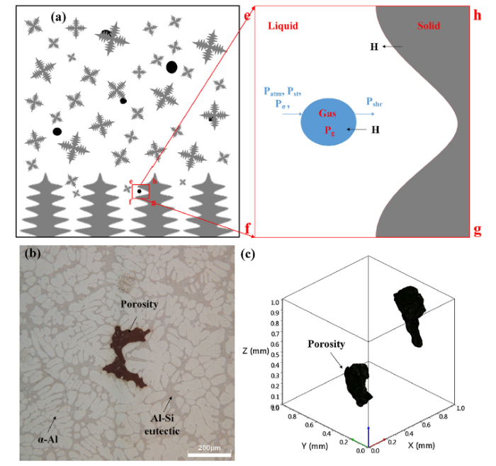
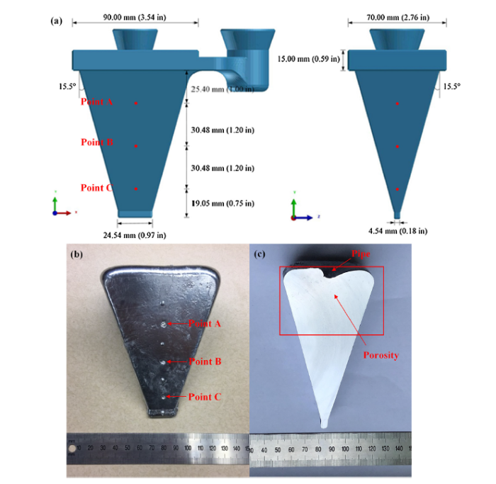
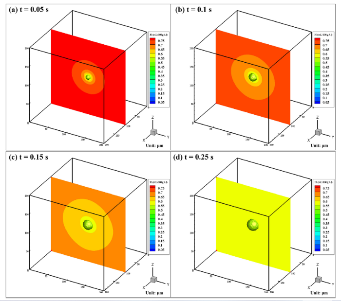
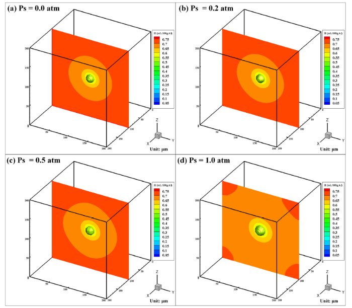
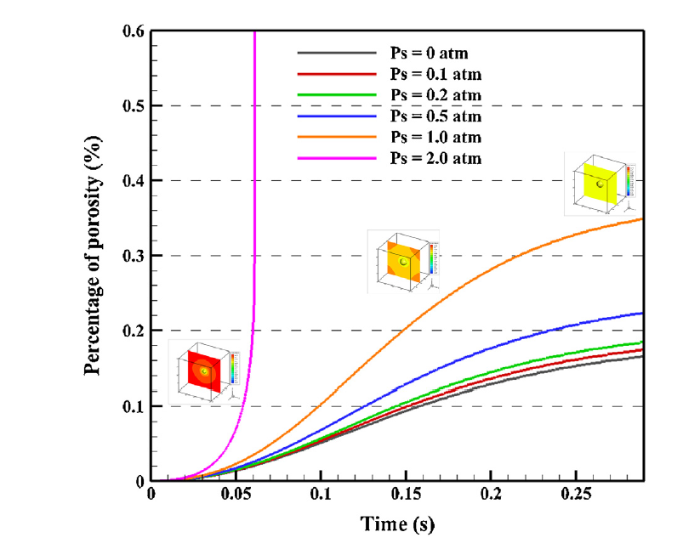
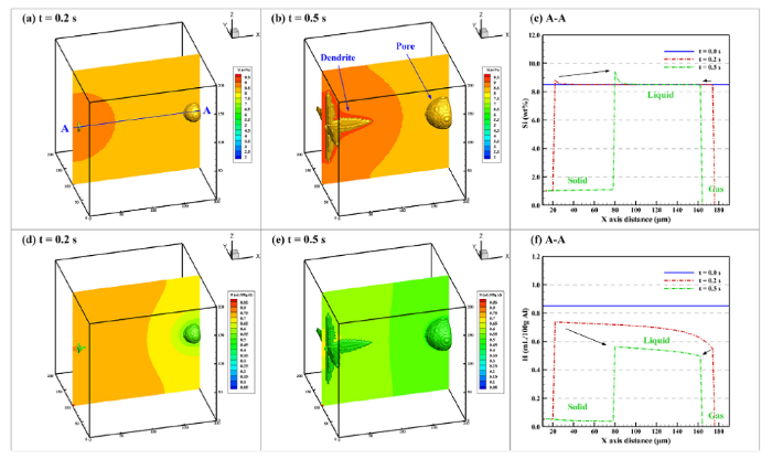
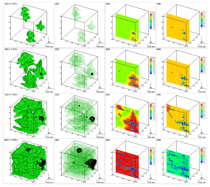
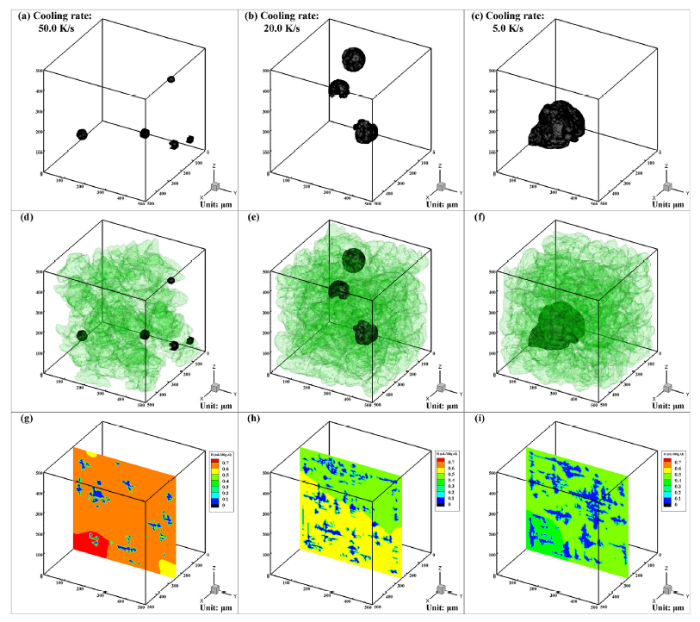
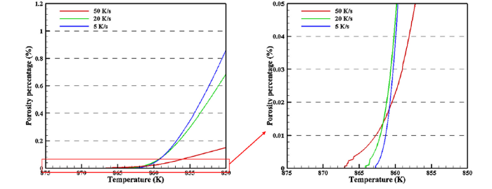
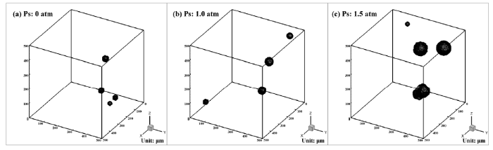
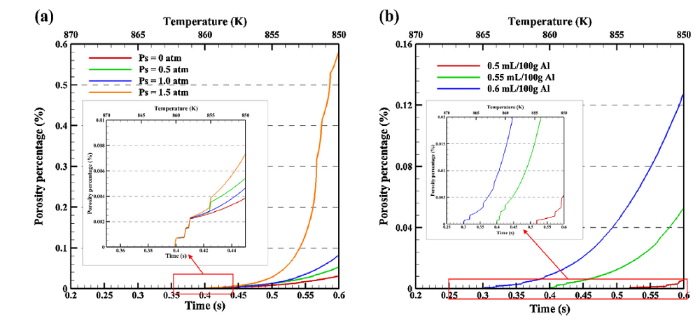
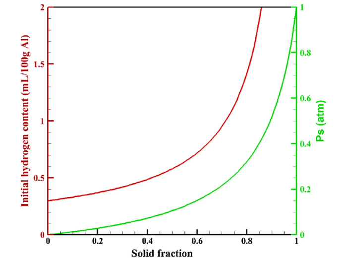
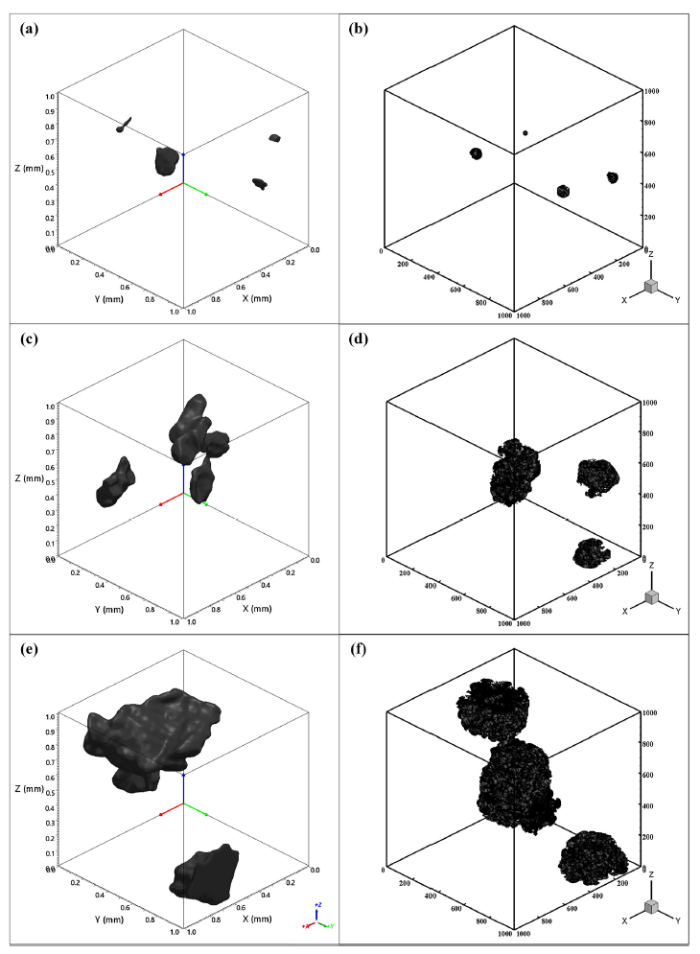
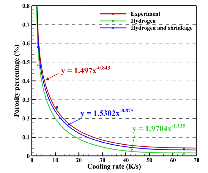


 WeChat