

1. Introduction
Structural materials with high strength and good ductility are required in modern society [1]. Grain refinement is an efficient strategy to enhance the strength according to the classical Hall-Petch relationship [2]. However, ductility deteriorates with grain refinement and the tradeoff relationship between strength and ductility generally exists [3]. A proper grain size is thus required to balance the comprehensive mechanical properties. Recently, a kind of novel ultrafine-grained (UFG) structure with fully recrystallized grains was reported, and these materials can possess excellent strength, ductility and fatigue properties [[4], [5], [6]]. The fully recrystallized structure means low-density defects in the grains, which makes the UFG specimen analogous to the coarse-grained (CG) counterparts in microstructure. In this case, all the specimens share the same microstructure except the grain size, making it possible to reveal the intrinsic Hall-Petch relationship by plotting grain sizes from the CG regime to the UFG regime. It is critical to evaluate the role of dislocation density, i.e. well-recrystallized specimens are short of dislocations and exhibits extra hardening phenomenon, in contrast, specimens with deformation structure can yield easily due to the easy activation of prestored dislocations [7,8]. In this view point, the Hall-Petch relationship of any material can be plotted in a wide range of grain sizes, but microstructures including the grain size and the prestored dislocation density should be considered.
Pure Cu has been investigated widely as a model material [9,10]. The Hall-Petch relationship was also reported after collecting the data from CG specimens [11,12]. Previous results indicate that the deformation mechanisms are consistent when the grain size is refined down to 3.8 μm, and the Hall-Petch relationship is also valid [12]. Unfortunately, it is challenging to further refine the grain size to the UFG regime since grains grow fast under heat treatment [4]. Among various methods, high-pressure torsion (HPT) technique is highly effective in refining microstructures and processing bulk samples [13]. Accordingly, it is a feasible way to process Cu by applying HPT and subsequent annealing to obtain UFG materials with recrystallized structure, and to further explore the Hall-Petch relationship in a wide range of grain sizes. In contrast to pure Cu, the hypoeutectic Cu-Ag alloy consists of immiscible Cu matrix and Ag precipitates, which generally share a cube-on-cube orientation relationship [14,15]. Fully recrystallized UFG Cu-Ag alloy with much finer grain size can be conveniently obtained by annealing the nanocomposites [14,16]. In this case, it is possible to extrapolate the mechanical behavior of pure Cu to finer grain sizes, and thus to compare with the Cu-Ag alloy.
2. Experimental
Pure Cu with a commercial purity of 99.9% and Cu-7 wt% Ag-0.05 wt% Zr (denoted as Cu7Ag) alloy were studied in this work. For the pure Cu, HPT and annealing resulted in mean grain sizes ranging from 0.51 μm to 4.2 μm. Meanwhile, a Cu plate with thickness of 20 mm was cold rolled to 1 mm and annealed to obtain CG specimens with the mean grain sizes ranging from 2.51 μm to 14.93 μm. The Cu7Ag alloy was processed by HPT and subsequent annealing to obtain recrystallized grains, and the mean grain sizes range from 117 nm to 444 nm. The microstructures and mechanical properties of these specimens were further characterized. The transverse section of the HPT disk and the RD-ND plane of the cold rolled sheet were examined by using scanning electron microscopy (SEM, LEO SUPRA 35) operated at 20 kV and transmission electron microscopy (TEM, FEI Tecnai F20) operated at 200 kV. All the mean grain sizes were measured by counting high-angle grain boundaries including twin boundaries. For the Cu and Cu-Ag alloy processed by HPT, tensile specimens with gauge length of 4 mm, width of 1 mm and thickness of 1.5 mm were cut. The gauge part of the tensile specimens was coincided to the position larger than 5 mm from the center of the disks to avoid the microstructural inhomogeneity in the near center regime. For the Cu prepared by cold rolling and annealing, tensile specimens with gauge length of 10 mm, width of 5 mm and thickness of 1 mm were cut from the cold rolled sheets. Tensile tests were conducted at an initial strain rate of 8.3 × 10⁻⁴ s-1 at ambient temperature. The 0.2% offset proof stress was treated as yield strength σYS. Detailed information about the experimental procedures can be found elsewhere [14,17].
3. Results and discussion
3.1. Microstructures of pure Cu and Cu7Ag alloy
For pure Cu and Cu7Ag alloy, fully recrystallized specimens with different grain sizes have been processed successfully. It is of value to note that the grain sizes fall into wide ranges. Typical microstructures of pure Cu in the micrometer regime and UFG regime are shown in Fig. 1(a) and (b). The fully recrystallized specimens consist of equiaxed grains and are dislocation free. The minimum d achieved is 0.51 μm since recrystallized grains grow fast under heat treatment. In contrast, a minimum d of 117 nm is obtained in the Cu7Ag alloy, and typical microstructures are shown in Fig. 1(c) and (d). Equiaxed recrystallized grains along with small Ag domains were detected in Fig. 1(c). Though misfit dislocations are expected along the Cu/Ag interfaces due to the different lattice constants, the Ag domains can be fully coherent with the Cu matrix due to the small domain size, as shown in Fig. 1(d) [14].
Fig. 1.

Fig. 1.
(a, b) Backscattered images of pure Cu with representative grain sizes, (c) TEM image of the recrystallized Cu7Ag alloy with mean grain size of 177 nm and (d) HRTEM image from the grain interior of the recrystallized Cu7Ag alloy.
3.2. Tensile properties of pure Cu and Cu7Ag alloy with different grain sizes
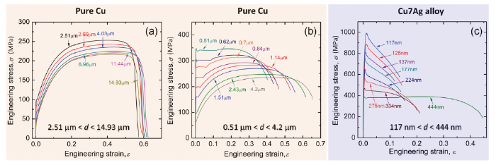
Fig. 2 demonstrates the tensile engineering stress-strain curves of pure Cu and Cu7Ag alloy with different grain sizes. For pure Cu, σYS and elongation change slightly when 2.51 μm < d < 14.93 μm, as shown in Fig. 2(a). In this case, all the specimens exhibit continuous yield behavior. With decreasing d, σYS was enhanced remarkably and discontinuous yield behavior along with Lüders deformation were detected [17]. For the Cu7Ag alloy, σYS becomes unprecedently high with grain refinement, as shown in Fig. 2(c). Considering the special cube-on-cube orientation relationship between Cu and Ag phases, it is anticipated that the Ag phase may not act as strong obstacle for plastic deformation, and the mechanical behavior of the Cu7Ag alloy may be analogous to pure Cu. In that case, the Hall-Petch relationships are examined and compared for the two kinds of materials.
Fig. 2.
When σYS is plotted against the inverse square root of d, the Hall-Petch relationship can be well described, as shown in Fig. 3. Three conclusions can be obtained accordingly. Firstly, σYS and d can be correlated with a two-stage Hall-Petch relationships. While stage I is in well accordance with previous reports in the CG regime, as indicated by the broken line [18], an extra stage II was detected when d is finer than ∼3 μm. The Hall-Petch slope in stage II is about 3 times that in stage I, indicating the onset of extra hardening effect in the fine-grained and UFG regime. Secondly, the Hall-Petch relationship is fitted well in the UFG regime for the Cu7Ag alloy. Thirdly, the stage II Hall-Petch relationship in pure Cu matches well with that in Cu7Ag alloy. On the one hand, this indicates that the mechanical behavior and deformation mechanism of Cu7Ag alloy is analogous to Cu. On the other hand, the present results provide indirect evidence that the Hall-Petch relationship of Cu is valid down to 100 nm without softening phenomenon. Note that UFG Cu with a mean grain size of about 200 nm has been obtained by HPT, but σYS is much lower than that predicted according to stage II Hall-Petch relationship, which can be induced by the easy activation of prestored mobile dislocations [19].
Fig. 3.
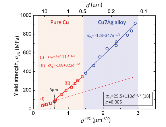
Fig. 3.
Plots of yield strength against the inverse square root of grain size for pure Cu and Cu7Ag alloy. The reported Hall-Petch relationship is indicated by the broken line.
3.3. Two-stage Hall-Petch relationship in various materials
Although the Hall-Petch relationship has been widely verified in various materials systems [2,23], multi-stage relationships were detected only in some special materials with well recrystallized structures or low-density defects, i.e. Al [7] and IF steels [21,22]. Recently, this phenomenon was also observed in Ni60Co40 and CoCrNi alloys [20]. Albeit the simple form of Hall-Petch relationship, many models were proposed to explore the physical meaning of the slope [24]. It has been reported that G and b play vital roles in determining the slope [2,25]:
where G is the shear modulus and b is the Burgers vector. Fig. 4(a) shows that k is positively related to Gb1/2 in stages I and II.
Fig. 4.

Fig. 4.
(a) Plot of Hall-Petch slope against (Gb)1/2 for Cu, Al [7], Ni60Co40 alloy [20], CoCrNi alloy [20] and IF steel [21,22] and (b) Plot of critical grain size dc against γ /(Gb) for Cu, Al [7], Ni60Co40 alloy [20] and CoCrNi alloy [20]. dc is related to the transition from stage I to II Hall-Petch relationship.
For the materials that exhibit multistage Hall-Petch relationships as mentioned above, the critical grain size dc dividing stages I and II was analyzed. In IF steel [21,22], pure Al [7] and Cu (this study), the transition from stage I to stage II Hall-Petch relationship is relevant to the discontinuous yield behavior, which is generally induced by the shortage of mobile dislocations in recrystallized grains. In the case of UFG structure, the density of grain boundaries is magnificently higher in contrast to the CG counterpart, in parallel, dislocation sources exist generally in the grain boundaries since the finite grain interior is short of dislocations. In this case, high stress is required to activate the dislocation sources. Once activated, lower stress is capable of gliding these generated dislocations. As a result, the measured σYS deviates from the value as predicted by conventional Hall-Petch relationship, exhibiting extra hardening behavior. In contrast to the dc = 3 μm of Cu in this work, it is interesting to note that a larger value of dc = 20 μm was reported in pure Al [7] while a smaller value of dc = 0.3 μm was reported in CoCrNi alloy [20]. It seems that the length scale of dc falls in a wide range covering about two magnitudes. Meanwhile, the stacking fault energy (SFE, γ) also ranges from about 22 mJ/m2 for CoCrNi alloy [26] to 150 mJ/m2 for pure Al [27]. When dc is plotted against γ /(Gb), a positive correlation is observed, as shown in Fig. 4(b). In other words, SFE might be a vital parameter for determining dc.
It has been widely reported that plastic deformation mechanisms of FCC materials are sensitive to SFE under quasi-static tensile tests at ambient temperature, i.e. dislocations glide in a wavy mode in high SFE materials, in contrast, the dislocation planar slip and deformation twinning prevail in low SFE materials [19,28]. For pure Al or Cu, the SFE is so high that the dislocations can glide easily via cross slip and cell structure forms in the grain interior after imposing specific strains. The shear stress and cell size can be described by the empirical law [29,30]:
where M =3.06 is the Taylor factor, σ is the flow stress, σ0 is the friction stress, D is the cell size, K* = 7.5 is a constant. Note that σ is always larger than σYS in order to facilitate the formation of cell structures. In order to simplify the calculation process, here we simply suppose that the dislocation cells form at the stress level of σYS, which is over simplified but can be convenient to give the cell size. For pure Al with d of 17 μm and σYS of 26.7 MPa [27], D is calculated to be 10 μm supposing that cell structure forms at this stress level. Similarly, we obtain D of 5.12 μm for pure Cu with d of 4.2 μm. These results show that the predicted D is comparable with the corresponding d, indicating that the free path for dislocation glide is so large that dislocations may easily annihilate in grain boundaries. This explains the discontinuous yield behavior and the transition from the stage I to the stage II.
For the CoCrNi alloy with low SFE, well-defined cell structure was not easily formed due to the highly planar mode of dislocation glide [26]. In that case, Eq. (2) cannot be applied to calculate D of the CoCrNi alloy. The planarity glide mode makes it possible to store dislocations and induce strain hardening even in a confined grain, which explains the very small dc of 0.3 μm in the CoCrNi alloy. Moreover, dc was also observed in several alloys with low SFEs, and again the value is always smaller than 0.5 μm [31]. It should be noted that such multi-stage Hall-Petch relationships were not reported in some low-SFE materials including TWIP steels [32], CoCrFeMnNi alloy [33] and Cu-11 at.% Al alloy [28] in our previous study. Since the minimum grain size of these fully recrystallized materials always is larger than 0.5 μm due to the rapid grain growth under heat treatment [4]. In other words, all the data of TWIP steels [32], CoCrFeMnNi alloy [33] and Cu-11 at.% Al alloy [28] still fall in stage I. Even though, it is reasonable to anticipate the dc and multi-stage Hall-Petch relationship in these materials under the prerequisite that such small recrystallized grain size can be achieved.
4. Conclusions
In summary, fully recrystallized pure Cu (0.51 μm < d < 14.93 μm) and Cu7Ag alloy (117 nm < d < 444 nm) were processed by HPT/cold rolling and annealing, and the Hall-Petch relationship was investigated in a wide range of grain sizes. The main conclusions can be summarized as follows:
(1) Two-stage Hall-Petch relationship was reported in pure Cu for the first time, and there exists a critical grain size dc of 3 μm which divides stages I and II.
(2) Although the stage I is well in accordance with previous reports, the stage II of Cu coincides well with the Cu7Ag alloy, manifesting similar deformation mechanisms and extrapolating the hardening effect down to 100 nm at least without softening in pure Cu.
(3) The magnitude of the critical grain size dc varies dramatically in different materials systems, and it is supposed to be correlated with the stacking fault energy.
The present conclusions are only applicable to the well annealed specimens, and any introduction of dislocations in the specimen may make softening effect and deviation from the Hall-Petch relation.
Acknowledgements
This work was supported financially by the Fundamental Research Funds for the Central Universities (No. N180204015). Y.Z. Tian, Z.F. Zhang and N. Tsuji were supported by Chinese Academy of Sciences (CAS) and Japan Society for the Promotion of Science (JSPS) through the Bilateral Program (No.GJHZ1774), and N. Tsuji was also supported by Ministry of Education, Culture, Sports, Science and Technology (MEXT), Japan, through the Elements Strategy Initiative for Structural Materials (ESISM) Project and the Grant-in-Aid for Scientific Research (S) (No. 15H05767).
Reference
DOI
URL
PMID
[Cited within: 1]

Conventional metals are routinely hardened by grain refinement or by cold working with the expense of their ductility. Recent nanostructuring strategies have attempted to evade this strength versus ductility trade-off, but the paradox persists. It has never been possible to combine the strength reachable in nanocrystalline metals with the large uniform tensile elongation characteristic of coarse-grained metals. Here a defect engineering strategy on the nanoscale is architected to approach this ultimate combination. For Nickel, spread-out nanoscale domains (average 7 nm in diameter) were produced during electrodeposition, occupying only ~2.4% of the total volume. Yet the resulting Ni achieves a yield strength approaching 1.3 GPa, on par with the strength for nanocrystalline Ni with uniform grains. Simultaneously, the material exhibits a uniform elongation as large as ~30%, at the same level of ductile face-centered-cubic metals. Electron microscopy observations and molecular dynamics simulations demonstrate that the nanoscale domains effectively block dislocations, akin to the role of precipitates for Orowan hardening. In the meantime, the abundant domain boundaries provide dislocation sources and trapping sites of running dislocations for dislocation multiplication, and the ample space in the grain interior allows dislocation storage; a pronounced strain-hardening rate is therefore sustained to enable large uniform elongation.

 WeChat