

$${\boxed{Nomenclature \\\\ σ_{s} \quad Yield stress \\\\ σ_{b} \quad Ultimate tensile strength \\\\ ν \quad Poisson’s ratio \\\\ E \quad Young’s modulus \\\\ Ψ \quad Elongation rate \\\\ Δh \quad Difference between flow stress and friction stress \\\\ K_{h} \quad Slope of the Hall-Petch plot \\\\ M \quad Taylor factor \\\\ α \quad Constant number \\\\ G \quad Shear modulus \\\\ P \quad Dislocation density \\\\ b \quad Burgers vector \\\\ P \quad Laser power density \\\\ T \quad Laser pulse duration \\\\ δ \quad Expansion degree \\\\ HCREP \quad Hertz contact rotary expansion process \\\\ LTP \quad Laser texturing process \\\\ DLC \quad Diamond-like carbon \\\\ CEP \quad Cold expansion process \\\\ CRS \quad Compressive residual stress \\\\ OM \quad Optical microscope \\\\ XRD \quad X-ray diffraction \\\\ TEM \quad Transmission electronic microscopy \\\\ SAED \quad Selected area electron diffraction \\\\ LSP \quad Laser shot peening \\\\ SP \quad Shot peening \\\\ }}$$
1. Introduction
Nickel-based superalloy are extensively applied in the metallic structures with fastener holes in aerospace and nuclear reactor industries due to its excellent corrosion resistance and thermal stability at elevated temperatures. However, these holes are usually regarded as the critical locations for crack nucleation and propagation in the whole structures under practical loading waveforms [1]. In order to maintain safe and steady operations of these structures, preferred surface integrity aiming at the holes is an efficient treatment to ensure the reliability and increase the lifetimes. In such a case, numerous cold expansion processes (CEPs) with inducing compressive residual stress (CRS) around the hole wall have been developed [2], [3], [4], [5], [6].
Based on the thickness of obtained CRS distributions, the CEPs can usually be divided into two groups. The first group includes deep rolling, shot peening as well as some combined processes (i.e., burnishing holes after drilling and reaming) [7], [8]. Although these techniques are simple and mature, the positive impact on the surface integrity around the hole wall still has room for improving. The second group, which induces a deeper CRS layer [9], [10], [11], mainly includes the direct mandrel expansion process [12], the split sleeve expansion process [13], the split mandrel expansion process [14], variable expansion process [15], the symmetric cold expansion [16], spherical mandrelling process [17] and the friction stir hole expansion (FSHE) [18]. Furthermore, according to the varied tool structures and movements of the tools used in the techniques, the second group can be further divided into three sub-groups: (i) mandrel impacting on the hole wall, (ii) mandrel impacting on the hole wall with sleeve, and (iii) mandrel impacting on the hole wall with rotation. The detailed introductions for the above-mentioned three sub-groups are exhibited as follow. (i) The direct mandrel expansion process [9] has simple tool structure and prominent CRS layer, but it may lead to the stacking of materials at the hole edge due to direct axial pushing effect of mandrel on the hole wall. (ii) Mandrel impacting on the hole wall with sleeve could effectively avoid the stacking of materials at the hole edge. However, it may result in the uneven circular CRS distribution and the appearance of stress concentration as a result of the asymmetric sleeve expansion. (iii) The spherical mandrelling process [17] and the friction stir hole expansion (FSHE) [18] are the newly developed techniques, which could prevent the defects of material stacking and uneven circular CRS distribution. Meanwhile, the local torsion, which is considered to be a significant plastic deformation process, has been induced into CEP [19], [20]. For the FSHE technique, the associated method covers both the macroscopic CRS effect and microscopic grain refinement [21], [22] effect at the same time. However, the direct face contact between the sleeve and hole wall may result in high contacting stress, severe friction and rapid tool wear. Furthermore, it should be noted that the above-mentioned CEPs are mainly applied on the hole components in aluminum and titanium alloys. The high hardness of nickel-based superalloys (∼440 HV) makes it difficult to be conducted by using these techniques.
In such a condition, to obtain uniform axial and prominent radial strengthening effect around the hole wall in nickel-based superalloy, a novel CEP technique called the Hertz contact rotary cold expansion process (HCREP) is developed in this study. The tools used in HCREP mainly involve a sleeve and a conical mandrel. Due to the extremely high hardness of nickel-based superalloy, the sleeve should be pretreated firstly by laser texturing process (LTP) for producing a large amount of recrystallized robust raised points on its cylindrical surface, in purpose of forming point contact instead of face contact between sleeve and the hole wall. Then, the diamond like coating (DLC) film is applied on sleeve surface to improve its wear-resistance and self-lubricative property [23]. As a consequence, the interaction between the rotating sleeve and hole wall, in conditions of sliding friction and interference fit, could lead to a significant plastic deformation layer.
In this paper, the feasibility of HCREP for improving the surface integrity of the hole wall is systematically studied. Section 2 presents the experimental procedures containing material treatment, LTP, HCREP and the characterization methods. In section 3, the optimized parameters in LTP are obtained. The surface integrity after the developed technique at different expansion degrees (δ) is described. The state characteristics of surface integrity and the microstructure evolution mechanism are discussed in section 4. Section 5 concludes the paper.
2. Material and methods
2.1. Experimental materials
The material used in this study is a rolled nickel-based GH4169 superalloy [24], the chemical compositions of which are listed in Table 1. The basic phases in GH4169 superalloy includes: matrix γ phase, Ni3Al type γ' and Ni3Nb type γ" strengthening phases. The mechanical properties are calibrated by the monotonic tensile test and the results show that the yield stress σs is 964.14 MPa, the ultimate tensile strength σb is 1294.6 MPa, the Young’s modulus E is 193.8 and the elongation is 19.48 %.
Table 1 Chemical compositions (wt.%) of the nickel-based GH4169 superalloy.
| C | Cr | Mo | Nb | Ti | Al | P | Mn | S | Fe | Ni |
|---|---|---|---|---|---|---|---|---|---|---|
| 0.023 | 17.86 | 2.98 | 5.38 | 0.99 | 0.57 | 0.012 | 0.03 | 0.001 | 18.75 | Bal. |
2.2. Experimental methods
The experimental methods include LTP and HCREP. Fig. 1 presented the preparation process of sleeve, which contained details of the LTP. The aim of LTP was to strengthen and roughen the surface of the sleeve. The equipment used in the LTP was composed of laser power devices and focusing lens which was incorporated with a CNC machine. The electric signal was modulated by the laser power device to generate laser pulses. The laser beam passed through focusing lens and located on the surface of the sleeve to form laser-textured points. The laser power density, P, and laser pulse duration, T, were important parameters affecting the 3D shape and microhardness of the textured points [25]. Thus, the orthogonal experiment was designed to study the effects of P and T on the 3D shape and microhardness of the textured points. The designed magnitudes of P and T were listed in Table 2. Finally, the treated sleeves by the LTP were coated with the hydrogenated diamond like coating (DLC) film by the physical vapor deposition technique on a direct current magnetron sputtering system, the goal of which was to further improve their surface hardness and self-lubricative property properties [26].
Fig. 1.
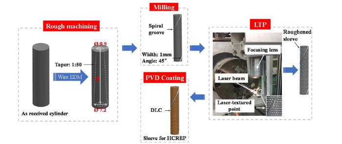
Fig. 1.
Preparation process of sleeve.
Table 2 The detailed parameters of P and T in LTP.
| Specimen ID | P (W/mm2) | T (μs) |
|---|---|---|
| LTP-1 | 3.06 × 10⁴ | 1000 |
| LTP-2 | 3.06 × 10⁴ | 1400 |
| LTP-3 | 3.06 × 10⁴ | 1800 |
| LTP-4 | 3.57 × 10⁴ | 1000 |
| LTP-5 | 3.57 × 10⁴ | 1400 |
| LTP-6 | 3.57 × 10⁴ | 1800 |
| LTP-7 | 4.07 × 10⁴ | 1000 |
| LTP-8 | 4.07 × 10⁴ | 1400 |
| LTP-9 | 4.07 × 10⁴ | 1800 |
The schematic illustration of HCREP was shown in Fig. 2. The tool used in HCREP mainly involves two parts, namely the sleeve obtained from the LTP, and the mandrel. The internal taper of sleeve and external tapper of conical mandrel are both 1:50. The HCREP was carried out by means of preliminarily assigned axial stroke and tangential rotary of the mandrel. The mandrel was driven by a spindle on the vertical driller. The first step of HCREP was that the mandrel should move down axially into the sleeve, leading to the radial expansion of the sleeve. When the expansion, δ, of the hole reached a certain setting value, the mandrel stopped moving axially. For the second step, the mandrel rotated circularly at a fixed speed of 66 r/min. To obtain different surface integrity state, the different setting values of δ (0.4 %, 0.7 %, 1%) were selected and marked as HCREP-1, HCREP-2 and HCREP-3, respectively. The as-received specimen was marked as AR. It should be noted that for better describing the axial CRS distribution, the upper, middle and bottom planes were assigned to the corresponding locations in Fig. 2.
Fig. 2.
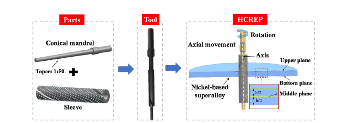
Fig. 2.
Schematic illustration of HCREP.
2.3. The characterization methods after the LTP and HCREP
After LSP treated, the 3D shape and microhardness of laser-textured point were characterized by IFMG4 surface shape analyzer and HXD1000TMC/LCD micro-Vickers hardness tester. A featured area of 286.63 × 217.45 μm was selected for observing the 3D shapes of LTP-1 to LTP-9, seen Table 2. The height of laser-textured points was automatically measured by the analyzing system. The Knoop indenter was used in the microhardness test, with load of 1.916 N and duration of 20 s. The indentation tests were repeated five times to obtain the average microhardness.
In order to improve the surface quality of the specimen after HCREP, the end surface was polished with sandpapers up to a mirror finish using DiaPro Dac diamond suspension. In addition, the end surface was etched in Nimonic etchant (10 mL HNO3, 50 mL HCl, 40 mL H2O, 2.5 g CuCl2), identifying the microstructure morphology of the plastic deformation layer based on optical microscope (OM) observations. The load and duration after HCREP used in microhardness measurement were the same as those used after LTP. The measuring position was on the end surface of the specimen with the range from the hole wall to the depth of 400 μm in the radial direction. The residual stress of hole specimens was measured using MG40 P FS STD residual stress tester, with Mn target to generate Kα radiance. The diffraction crystal face was {311}, Bragg angle was 151° and the scanning speed was 0.1 %. The in-depth distribution of the residual stress was measured using an electro-chemical polishing method, with electrolyte of saturated NaCl solution and 15 mA current. The surface roughness (Ra) of specimens was measured using WYKO NT9300 optical profiler. For revealing the microstructure evolution mechanism in the strengthened hole, the topmost surface and in-depth dislocation evolutions were characterized by JEM-2100 F the transmission electron microscopy (TEM). The specimen was prepared in the following method. First, a layer of 0.4 mm thick slice of the inner hole surface was cut by wire EDM. Then the slice was grinded by the sandpaper until it reached the thickness required for observation. Finally, the TEM specimen for observation was prepared by the focused ion beam thinning method.
3. Results
3.1. The optimized parameters in LTP
Fig. 3 shows the 3D topographies of the laser-textured points for P and T, see in Table 2. When the laser beam acted on the surface of the material, a molten pool with spherical crown topography is formed due to the combined effect of Marangoni convection and natural convection [25]. The maximum height of the laser-textured point is 10.28 μm under the condition of P = 4.07×10⁴ W/mm2 and T =1400 μs. As depicted in Fig. 3, the maximum height of the laser- textured point increases with the increasing of P, while fluctuated with different T at specific P. Fig. 4 shows the microhardness of the laser-textured points under different parameters. The microhardness of GH4169 is used as a benchmark and the value is 440 HV which is similar to that measured by Yang et al [27]. The microhardness of the laser-textured points is in the range of 600-800 HV. This phenomenon illustrates that the surface of the sleeve is strengthened by LTP. When the the laser power density is 4.07 × 10⁴ W/mm2 and laser pulse duration is 1400 μs, the laser-textured points show maximum hardness and height of the 3D topography. Consequently, the laser power density of 4.07 × 10⁴ W/mm2 and pulse duration of 1400 μs are selected as the optimized parameters for LTP.
Fig. 3.
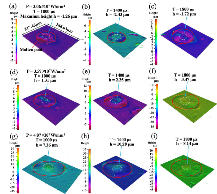
Fig. 3.
Three-dimensional topographies of the laser-textured points for different laser power densities and laser pulse durations.
Fig. 4.

Fig. 4.
The microhardness and the maximum height of the laser-textured points in different LTP parameters.
3.2. Surface integrity after HCREP
Metallographic observation is the most direct reflection of the effect of HCREP. Fig. 5 shows microscopic metallographic structures of the AR and strengthened specimens with varied δ. No plastic deformation layer is observed in the AR, as shown in Fig. 5. However, gradient distributed plastic deformation layers with depths of 27.54 μm, 41.25 μm, and 65.58 μm are respectively formed for HCREP-1, HCREP-2 and HCREP-3.
Fig. 5.
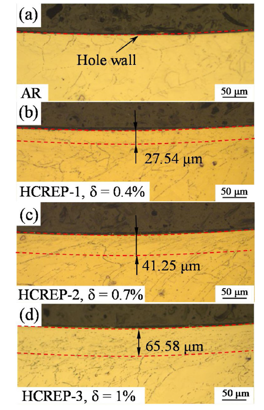
Fig. 5.
Microscopic metallographic structures of the (a) untreated material and strengthened materials with expansion degrees of (b) 0.4 %, (c) 0.7 %, and (d) 1%.
TEM is carried out on the top surface of AR and HCREP-3 specimen to further characterize its microstructure as shown in Fig. 6. The annealing twins are observed according to the selected area electron diffraction (SAED) pattern at the grain boundary of the untreated specimen as depicted in Fig. 6a. The TEM images show that grain refinement leads to nanocrystals on the topmost hole surface of HCREP-3, with the size of 69 nm, which is determined by the SAED patterns inserted in Fig. 6b. Fig. 6b-e illustrate the in-depth dislocation evolution of HCREP-3. As shown in Fig. 6c, the dislocation cells and dislocation tangles are observed at a depth of 30 μm. Meanwhile, nanocrystals are still existing via the observation of SAED ring pattern. As we can see in Fig. 6d, the sizes of the dislocation cells in this layer are larger than those at a depth of 30 μm. The slender deformation twins appear, and the SAED pattern identify the twinning mode as face-centered cubic (FCC), which is a frequently observed twining type in the GH4169 superalloy. The grain size increases with the increased depth from the topmost surface, and the degree of plastic deformation features a gradient variety from surface to interior of specimen after HCREP.
Fig. 6.

Fig. 6.
TEM images of the topmost surface of (a) AR and (b) HCREP-3, and (c) 30 μm, (d) 60 μm deep layer of the HCREP-3.
The in-depth micro-hardness distribution of untreated and HCREP treated hole specimen is shown in Fig. 7. The microhardness of the untreated specimen is around 440 HV, whereas the microhardness near the hole wall is 473 HV, which is caused by the drilling process [4]. After HCREP, the micro-hardness on the hole sub-surface increases significantly where HCREP-1 is 542 HV, HCREP-2 is 550 HV and HCREP-3 is 548 HV, which is 26.05 %, 27.9 %, and 27.44 % higher compared to AR. The range of the error bar is less than 5%, which means these errors will not affect the validity of the conclusion. The results demonstrate that the δ has only a slight influence on the absolute value of the maximum microhardness. The micro-hardness also exhibits a gradient distribution along the radial depth.
Fig. 7.

Fig. 7.
The microhardness evolution curves with varied depth from the hole wall at different expansion degrees.
Fig. 8 shows CRS in-depth distribution of hole specimens after HCREP in the position of upper plane, middle plane and bottom plane. The results demonstrate that the maximum CRS occurred at about 0.2 mm deep from the hole wall. The peak values are similar for the different δ (-806 MPa, -898 MPa, and -877 MPa for HCREP-1, HCREP-2, HCREP-3 respectively), indicating that the δ have only a minor influence on the peak CRS values. However, the corresponding depth of the CRS layer is increased from 600 μm to 900 μm. The CRS values decrease gradually with increase of depth, at different δ. Minor differences of the CRS are observed for the three planes at the δ = 0.4 %, and the differences increase with increased expansion degrees. The maximum value of the CRS at the bottom plane is 200 MPa less than that of the other position in the HCREP-2 and HCREP-3, showing an uneven distribution of the CRS radially. The CRS values resulted from laser shot peening (LSP) and shot peening (SP) [28], [29] are presented in Fig. 8c. After undergoing LSP at 30 J, the stress displaying a broader extent of compressive stress depth through 0.7 mm, and the maximum CRS is 250 MPa. For the SP method, at the same coverage of 100 %, the maximum value of the CRS increased from -629 MPa to-687 MPa as the SP intensity increased from 13.1 A to 28.1 A. These results show that the SP and LSP methods result in lower CRS values and thinner CRS layers than the HCREP.
Fig. 8.
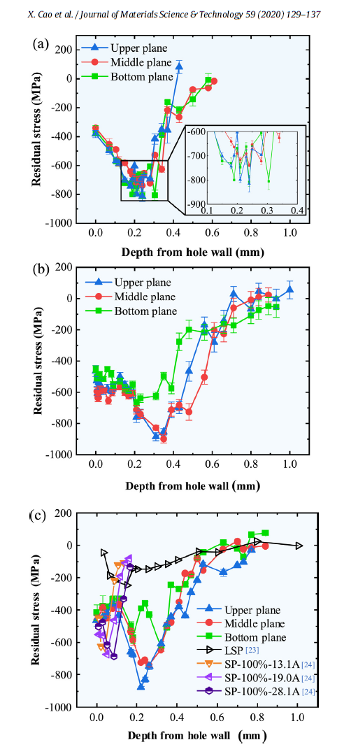
Fig. 8.
The residual stresses of specimens with different expansion degrees: (a) 0.4 %, (b) 0.7 %, (c) 1%.
The surface roughness of the hole surface after HCREP is shown in Fig. 9. As shown in Fig. 9a, the untreated specimen (AR) exhibits an Ra value of 443.73 nm. After HCREP, however, the surface roughness of hole surface is reduced. As presented in Fig. 9b-d, the Ra values of HCREP-1, HCREP-2 and HCREP-3 are respectively 251.01 nm, 371.79 nm, and 439.71 nm. The roughness values of these three specimens are respectively 43.43 %, 16.21 %, and 0.9 % lower than that of the AR. The surface roughness of the strengthened specimens is found to increase with the δ. The results indicate that the surface roughness of hole walls is not degraded by the HCREP.
Fig. 9.

Fig. 9.
Surface topographies of the (a) untreated specimen and the specimens with expansion degrees of (b) 0.4 %, (c) 0.7 %, and (d) 1%.
4. Discussion
The plastic deformation comes from the plastic accumulates on the hole wall which varies from the top surface to interior gradually under the HCREP treatment. After HCREP, massive dislocations and deformation twins are generated due to the severe plastic deformation, which will then eventually cause grain refinement at the hole wall. The grain refinement results along the radial direction in the HCREP are shown in Fig. 9. As the dislocation tangles aggregate at the grain boundaries, dislocation walls are formed, resulting in impeding the movement of the dislocation. Then, high dislocation density will be generated in grains with further plastic deformation, also leading to a high grain boundary energy. In order to keep the stability of grain boundaries, dislocation annihilation and recombination occur in the region of dislocation tanglings and dislocation walls. As the strain energy continues increasing, these dislocation tanglings and walls turn into dislocation cells, then transfer to small-sized sub-grains by absorbing dislocations as shown in Fig. 5c. Meanwhile, the dislocation annihilation also occurs at sub-grain boundaries, which results in the dislocation slip along sub-grain boundaries. With the further increase of strain energy, dislocation tanglings and dislocation walls are formed again in refined sub-grains and grains. The above microstructural evolution is repeated in refined sub-grains and grains, which causes further grain refinement. Finally, nanocrystals are formed in the deformation layer after HCREP. As the distance from the topmost surface of the hole increases, the strain energy decreased, which will lead to the decreased driving force for grain refinement. Thus, the gradient structure which includes various grain size can be observed in Fig. 6. The microhardness also has a gradient distribution along the radial depth, which may come from the varied dislocation density and grain structure. The Taylor equation is used to analyze the relationship between the strength and the dislocation density [30]:
where M is the Taylor factor, α is a constant, G is the shear modulus, b is the Burgers vector magnitude, Kh is the slope of the Hall-Petch plot, and ρ is the dislocation density. The Taylor equation implies that there is a linear relationship between the dislocation density and the microhardness. Hence, the grain refinement caused by the microstructure evolution increases the microhardness of the material. The plastic accumulation decreases with the depth increment, resulting in lower dislocation density and micro hardness at greater depths. The inverse variation tendency between the grain size and the microhardness is described by the Hall-Petch theory as discussed in the references [31], [32], [33]. A larger expansion degree is conductive to a larger plastic regime in which a deeper CRS layer is generated and subsequently contributes to an increase in the microhardness [34]. The microhardness in the surface region is found to be less than that in the sub-surface region, which can be explained by predominant thermal softening, as the thermal energy has a significant effect on the mechanically-induced deformation [35], [36], [37]. The plastic deformation leads to grain refinement and increase of dislocation density as well as introduces compressive residual stress. In addition, the increase in the microhardness at the surface is found to be the result of the presence of residual stress, which has been demonstrated in other studies [33], [34].
The CRS distribution along the radial direction is similar to that of micro hardness which also can be explained by the uneven plastic deformation resulted from the different grain refinement at varied depth. For further understanding the gradient distribution of CRS along the axial direction, the stress state of a point near the hole surface during different CEPs is described in Fig. 10. A point near the hole surface is selected as shown in Fig. 10a. The stressed state, depicted in Fig. 10b, is characteristic of all points on the hole surface for the symmetric cold expansion process [16], which induces a minimal and symmetrical gradient in the middle plane in the axis direction of the hole. However, the stress state of the direct mandrel expansion process [12] changes by the presence of the tangential stress (τrz = τzr) as shown in Fig. 10c, which results in non-symmetrical residual stress gradient in the middle plane along the hole axis. In Fig. 10d, additional tangential stress ((τrθ = τθr)) and angular strain (γrθ = γtθ) occur due to the friction forces resulted from the rotation of the sleeve in the hole during the HCREP. The tangential stress and angular strain may be account for the reduced circular CRS gradient in the HCREP.
Fig. 10.
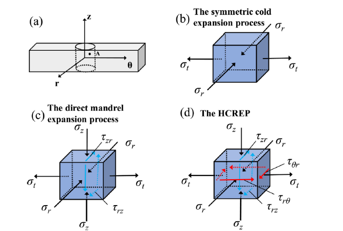
Fig. 10.
Stress states of a point near the hole surface: (a) a point near the hole surface, (b) The symmetric cold expansion process, (c) The direct mandrel expansion process, (d) The HCREP.
Moreover, in this study, the δ has different influence on the surface integrity state. The maximal value of the micro hardness and CRS in the radial direction are found to be expansion degrees independent. The expansion process is discontinuous based on the former work hardening, which means that the improvement of the microhardness and CRS requires more driving energy. However, the experiment parameters remain the same during the HCREP which may result in the less effect on the maximum microhardness and CRS values under different δ. While the depth of plastic deformation layer, the work hardening layer and CRS layer in radial direction increases with the increased δ. The reason for this phenomenon is that an increase in δ results in greater plastic deformation.
5. Conclusions
In this work, a novel HCREP method called is established and its effect on improving hole surface integrity of nickel-based superalloy is investigated. The conclusions are listed as follows.
(1) The laser power density and pulse duration in the LTP are optimized to be 4.07 × 10⁴ W/mm2 and 1400 μs, respectively.
(2) A plastic deformation layer with higher micro hardness and better surface roughness is formed around the hole wall after HCREP. Correspondingly, a CRS layer is observed. These results are found to be related to the grain refinement at the top layer. Meanwhile, the axial CRS is distributed uniformly due to the tangential stress and angular strain during the HCREP.
(3) The surface integrity is determined at different δ (0.4 %, 0.7 %, and 1%). The depth of the plastic deformation layer is increased with the δ. Additionally, the results demonstrate that the maximum values of microhardness and CRS are only slightly affected by the δ, whereas the thicknesses of the work hardening layer and CRS layer increases with the increase markedly of the δ.
Acknowledgements
This work was sponsored by the National Key Research and Development Program of China (2018YFC1902404), the National Natural Science Foundation of China (51725503, 51705155), Innovation Program of Shanghai Municipal Education Commission (2019-01-07-00-02-E00068).
Reference
DOI
URL
PMID
[Cited within: 1]

Nanotwinned (nt) materials exhibit excellent mechanical properties, and have been attracting much more attention of late. Nevertheless, the fundamental mechanism of interaction between dislocations and a single nanotwin is not understood. In this study, in situ transmission electron microscopy (TEM) nanoindentation is performed, on a specimen of a nickel (Ni) alloy containing a single nanotwin of 89 nm in thickness. The specimen is prepared using focused ion beam (FIB) technique from an nt surface, which is formed by a novel approach under indentation using a developed diamond panel with tips array. The stiffness of the specimen is ten times that of the pristine counterparts during loading. The ultrahigh stiffness is attributed to the generation of nanotwins and the impediment of the single twin to the dislocations. Two peak loads are induced by the activation of a new slip system and the penetration of dislocations over the single nanotwin, respectively. One slip band is parallel to the single nanotwin, indicating the slip of dislocations along the nanotwin. In situ TEM observation of nanoindentation reveals a new insight for the interaction between dislocations and a single nanotwin. This paves the way for design and preparation of high-performance nt surfaces of Ni alloys used for aircraft engines, gas turbines, turbocharger components, ducts, and absorbers.
Fastener holes used in the mechanical joints are vulnerable to failure due to development of stress concentration at their edges. Inducing compressive residual stresses by different techniques has been the most common method to reinforce the holes to date. In this work, a new reinforcement technique called internal torsion, which can be classified as a localized severe plastic deformation process, is proposed as an alternative to the cold expansion pre-stressing. A special specimen is designed to represent the behavior of a typical fastener hole during the internal torsion process. The deformation of the specimen in the vicinity of its hole surface is studied by introducing a parametric kinematically admissible velocity field (PKAVF) within the deformation affected zone (DAZ). Calibration of the parameters in relation to the deformation of the material during the process is done by an elastic-plastic finite element solution that was performed in ABAQUS for a specimen made of interstitial free (IF) steel. Numerical analysis of the deformation is carried out to understand the process and to estimate the optimum process parameters. Subsequently, the calibrated model is used in an upper-bound solution of the problem to estimate the torque-twist response of the specimen during internal torsion. Finally, the results of upper-bound solution are compared with those of finite element analysis. There is a good agreement between the upper-bound solution and finite element results, which verifies validity of the calibrated velocity field model and the upper-bound solution based on the model for the internal torsion problem.
DOI
URL
PMID
[Cited within: 1]
Signaling through the Ror2 receptor tyrosine kinase promotes invadopodia formation for tumor invasion. Here, we identify intraflagellar transport 20 (IFT20) as a new target of this signaling in tumors that lack primary cilia, and find that IFT20 mediates the ability of Ror2 signaling to induce the invasiveness of these tumors. We also find that IFT20 regulates the nucleation of Golgi-derived microtubules by affecting the GM130-AKAP450 complex, which promotes Golgi ribbon formation in achieving polarized secretion for cell migration and invasion. Furthermore, IFT20 promotes the efficiency of transport through the Golgi complex. These findings shed new insights into how Ror2 signaling promotes tumor invasiveness, and also advance the understanding of how Golgi structure and transport can be regulated.
AbstractThe microstructural evolution during cold rolling of IF-steel up to reductions of 90% has been investigated using scanning and transmission electron microscope techniques. The deformation microstructures consist of similar features to those already identified in several FCC metals, namely cell blocks showing a pattern of subdivision on two levels. An important difference compared to FCC metals is an increased prevalence of strain localization, seen most directly by highly localized micro-shearing. An orientation dependence of the deformed microstructure is observed in that nearly all the extended dislocation boundaries and micro-shear traces are crystallographic, coincident either with {1 1 0} or {1 1 2} slip planes. A sharp fall in ductility seen between rolling reductions of 30% and 50% is attributed to the onset of localized micro-shearing. A flow stress calculation, based on linearly additive contributions from dislocation and grain boundary hardening, leads to flow stress values and a strain hardening behavior in good agreement with experimentally determined values.]]>
AbstractFocusing on nanocrystalline (nc) pure face-centered cubic metals, where systematic experimental data are available, this paper presents a brief overview of the recent progress made in improving mechanical properties of nc materials, and in quantitatively and mechanistically understanding the underlying mechanisms. The mechanical properties reviewed include strength, ductility, strain rate and temperature dependence, fatigue and tribological properties. The highlighted examples include recent experimental studies in obtaining both high strength and considerable ductility, the compromise between enhanced fatigue limit and reduced crack growth resistance, the stress-assisted dynamic grain growth during deformation, and the relation between rate sensitivity and possible deformation mechanisms. The recent advances in obtaining quantitative and mechanics-based models, developed in line with the related transmission electron microscopy and relevant molecular dynamics observations, are discussed with particular attention to mechanistic models of partial/perfect-dislocation or deformation-twin-mediated deformation processes interacting with grain boundaries, constitutive modeling and simulations of grain size distribution and dynamic grain growth, and physically motivated crystal plasticity modeling of pure Cu with nanoscale growth twins. Sustained research efforts have established a group of nanocrystalline and nanostructured metals that exhibit a combination of high strength and considerable ductility in tension. Accompanying the gradually deepening understanding of the deformation mechanisms and their relative importance, quantitative and mechanisms-based constitutive models that can realistically capture experimentally measured and grain-size-dependent stress–strain behavior, strain-rate sensitivity and even ductility limit are becoming available. Some outstanding issues and future opportunities are listed and discussed.]]>

 WeChat