

1. Introduction
High Nb containing TiAl alloys are considered as potential alternative materials for high-temperature applications, owing to its high specific strength, creep and oxidation resistance [[1], [2], [3]]. However, the relatively low ductility (<2%) and toughness of the alloys processed using traditional methods, such as casting or forging, is still of barrier which inhibits its application [[1], [2], [3], [4], [5]]. Directional solidification (DS) is a practical route to solve this problem because polysynthetically twinned (PST) TiAl crystals exhibit superior ductility and toughness compared with the polycrystalline TiAl alloys [6,7]. These PST TiAl crystals exhibit the best balance between strength and ductility when the lamellar boundaries are parallel to the loading direction [[6], [7], [8]]. However, preparation of high-Nb TiAl PST crystals is considered to be more difficult than other α solidified TiAl alloys [9]. Nb behaves as a β stabilizer in TiAl systems, a large Nb addition turns the solidification route towards β primary phase type [9,10]. In that situation, grains with final lamellar boundaries 0° or 45° against the growth direction will all have chances to nucleate [9,10]. In actual solidification process, the two group of grains tend to exhibit a competitive growth and the final microstructure frequently turns out a mixed type [7,11].
Liu et al. tried to prepare Ti-46Al-8Nb (at.%) PST crystals in a Bridgman-type furnace under a wide growth rate range from 1 to 70 μm/s, but did not succeed as all the crystals they prepared consisted of more than one grain [12]. Ding et al. managed to prepare Ti-46Al-5Nb PST crystals using a double DS method in Bridgman-type furnace with ceramic mold [13,14]. However, Y2O3 particles were included in the crystals and they led to significant reduction in ductility [15]. Optical floating zone furnace was introduced to the preparation of TiAl PST crystals. The DS process takes place in an enclosed quartz chamber without crucible and it can in turn avoid the contamination [16,17]. With this furnace, Johnson et al. developed the seed technique and successfully controlled the microstructure of TiAl alloys with a series of compositions [8,9,18]. They proposed an “Al-equivalent” method to predict the appropriate composition for successful seeding. According to this theory, only alloys with a narrow range of compositions are appropriate for successful seeding [9]. Especially, for Al-lean TiAl alloys, successful seeding is difficult due to the large volume fraction of β phase [9]. In recent years, engineering TiAl alloys have a tendency towards Al-lean side [3,4], therefore it is of great importance to analyze the seeding process for those Al-lean and high Nb containing TiAl alloys. The present work aims to investigate the possibility of preparing PST crystals of Ti-46Al-8Nb alloy. The widely used Ti-43Al-3Si seeds were prepared and introduced in the solidification process. The influence of β phase on the seeding procedure will be fully discussed.
2. Experimental
Button ingots were arc melted in a water-cooled copper crucible, and then drop cast into a cylindrical steel mold measuring 9 mm in diameter and 100 mm in length. The button ingots were re-melted and flipped over at least eight times to ensure the composition homogeneity. The DS was conducted in an FZ-T-12000-X-VP-S type optical floating zone furnace and the final processed DS bars were typically 60-80 mm in length. The Ti-43Al-3Si drop-cast bars were firstly directionally solidified at the growth rate of 180 mm/h. Several cylindrical sections measuring 6 mm in diameter were then cut from these bars transversely. These sections were rotated by 90° to serve as the initial seed [8,18]. The ultimate Ti-43Al-3Si seeds were prepared from these initial seeds at the growth rate of 5 mm/h. The feeder bars and seeds were both partially melted before the connection. For Ti-46Al-8Nb alloy, seeding process were conducted by using these ultimate seeds with our new operation illustrated in Fig. 1. The initial growth rate was 5 mm/h, and then the growth rate was increased to 10-40 mm/h when the as-grown bar had reached a length of 10 mm.
Fig. 1.

Fig. 1.
Schematic process of a new operation showing: (a) Ti-46Al-8Nb bar at the center of heating area while Ti-43Al-3Si seed was placed a little distance away from the heating center; (b) lifting up the seed rapidly and the heating power was reduced for a while; (c) rotation after 5 mm of the crystal growth had been accomplished.
The DS bars were then longitudinally sectioned and subjected to standard metallographic analysis. Specimens were etched by a solution consisted of 3% HF-5% HNO3-92% H2O by volume and microstructures were characterized by optical microscopy (OM). Tensile samples were machined from PST crystals grew at the rate of 10 mm/h. These standard tensile specimens have the rod dimension of Fig. 2, and were electropolished in a solution consisted of 10% HClO4-30% η-butanoln-60% methanol by volume at the temperature of -40 °C. An initial strain rate of 3 × 10⁻⁴ s-1 before yielding and 1.6 × 10⁻³ s-1 after yielding was used according to ISO 6892-1: 2009. Yield strength was measured by the 0.2% strain offset method. Elongation values were detected by an extensometer.
Fig. 2.
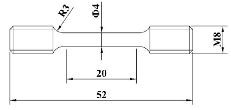
Fig. 2.
Shape and dimensions of standard tensile specimens (unit: mm).
3. Results and discussion
3.1. Microstructure of Ti-43Al-3Si seeds
Fig. 3 shows the longitudinal microstructures of Ti-43Al-3Si seed materials. The lamellar boundaries of initial seeds lie perpendicular to the growth direction, as is shown in Fig. 3(a). The ultimate seeds consisted of only one grain with the lamellar boundaries paralleling to the growth direction, as is shown in Fig. 3(b). The precipitates observed in Fig. 3(a) and 3(b) were identified as silicide particle [8,18].
Fig. 3.
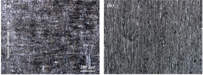
Fig. 3.
Longitudinal microstructures of Ti-43Al-3Si seed materials grew at the rate of (a): 180 mm/h and (b) 5 mm/h.
3.2. Microstructure of Ti-46Al-8Nb PST crystals
Fig. 4 shows the microstructure of seeded grew Ti-46Al-8Nb PST crystals at the growth rate of 10 mm/h. The whole DS bar consisted of only one grain (Fig. 4(a)). Lamellae of the PST crystals are aligned parallel to the growth direction and are continued from those of the seed (Fig. 4(b)). The main body of the Ti-46Al-8Nb PST crystals can be distinguished by the brightness contrast against the seed, due to the different responses to the etchant.
Fig. 4.
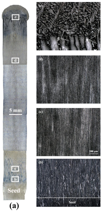
Fig. 4.
Optical microstructures of the Ti-46Al-8Nb PST crystals from a Ti-43Al-3Si seed at the growth rate of 10 mm/h, showing (a) the microstructure of the whole bar; (b) the magnified microstructure around the seed/main body interface; (c, d) the typical microstructure of the main body and (e) the dendrites morphology in the quench zone .
It was believed that large difference in composition between seed and feeder bar could lead to the formation of large mushy zone [11,[19], [20], [21]]. This could lead to the failure of seeding process at the beginning. Since the difference of composition between Ti-46Al-8Nb and Ti-43Al-3Si is rather large, to avoid the potential formation of mushy zone, some new operation skills illustrated in Fig. 1 were introduced. Before the connection of feeder bar and seed, Ti-46Al-8Nb bar was placed at the center of heating area and was sufficiently heated while the Ti-43Al-3Si seed was placed a little distance away from the heating center (Fig. 1(a)). Connection of the seed and feeder bar was accomplished by rapidly lifting up the seed. After that, the heating power was slightly reduced for a few minutes, and then recuperated to the normal values (Fig. 1(b)). These operations were aimed to reduce the melting of the seed material because the melting temperature of Ti-43Al-3Si alloy is lower than Ti-46Al-8Nb alloy [22,23]. Rotation of the seed and feeder bar was only allowed after 5 mm of crystal growth had been accomplished (Fig. 1(c)). After that, the melting zone should be taken care to ensure the steady solidification during the whole process, and quenching operation was accomplished by quickly separating the feeder bar and the DS bar.
All these new operations can reduce the mass convection at the beginning of the seeding process. The less convection can reduce the possibility of mushy zones and increase the success rate for seeding process. The Ti-43Al-3Si seed is the only source for silicon element, so the distribution of silicide particles reveals the degree of convection. From Fig. 4(b, c), obvious silicide particles only existed in the area just a few millimeters away from the seed/feeder interface, revealing the low extent of convection. The successful seeding at the beginning proved that the new operations are effective in preventing the formation of mushy zone. As shown in Fig. 4(d), the parallel lamellar microstructure was continuous till the end of as-grown crystals, which reveals the successful seeding of the whole bar. Fig. 4(e) shows the dendritic morphology at the quenched end of Ti-46Al-8Nb PST crystals. The β dendrites with orthogonal arms were found coexisted with α dendrites with a six-fold symmetry.
For alloy solidified at the growth rate of 20 mm/h, the seeding process was also successful, the lamellar microstructure was aligned parallel to the growth direction from the beginning part of the as-grown crystal (Fig. 5(a)) to the area around the quench zone (Fig. 5(b)). If the growth rate increased to the higher level, that is 30 or 40 mm/h, the final lamellar microstructure was found to be aligned to incline to the growth direction and this represented the failure of seeding process, as shown in Fig. 6(a, b). Large amount of B2 phase was found for all the alloys solidified at the growth rate range from 5-40 mm/h. Especially for PST crystals with a final parallel lamellar microstructure, B2 phase had a columnar morphology and aligned parallel to the growth direction coexist with the γ/α2 lamellae, as is shown in Fig. 5(a, b).
Fig. 5.
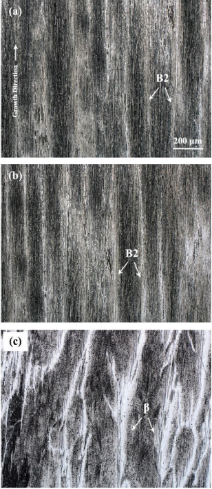
Fig. 5.
Optical microstructures of the Ti-46Al-8Nb PST crystals grew at the growth rate of 20 mm/h, showing (a) the microstructure of the beginning; (b) the microstructure of the end part of main body; and (c) the untransformed β dendrites morphology near the quench zone.
Fig. 6.
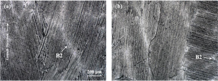
Fig. 6.
Typical microstructures of the Ti-46Al-8Nb alloy grew at the rate of (a) 30 mm/h and (b) 40 mm/h.
3.3. Peritectic solidification model
According to the “Al-equivalent” method by Johnson et al., the appropriate Al content for 8% Nb addition can be calculated as CAl = 47+(0.15 × 8) = 48.2 [9]. This indicates that the microstructure of Ti-48Al-8Nb alloy could be well controlled by the Ti-43Al-3Si seed. Johnson et al. believed that the Ti-43Al-3Si (α phase) seed could control the microstructure of metastable α-phase which nucleates directly from the liquid, but may be noneffective for β phase. The seeding process would be interrupted if the volume fraction of β phase is too large [9]. For Al-lean side TiAl alloys, such as Ti-46Al-8Nb, it is rather difficult to form the metastable α phase and the volume fraction of β phase is relatively high [9]. Therefore, seeding of these alloys may be rather difficult. However, it should be noted that this prediction is in contradiction with the results of the present work.
To explain the seeding process of Ti-46Al-8Nb alloy, a new model was proposed and the schematic process is shown in Fig. 7. According to the partial isopleth diagram of Ti-Al-Nb ternary system with 8% Nb addition [23], the primary phase of Ti-46Al-8Nb alloy can be confirmed as β phase. These β phase grains would adopt their preferential growth along the <100> direction and the β/liquid interface reveals the morphology of cellular or dendritic growth [10]. The nucleation and growth of β phase will cause the segregation, which makes Al rich in liquid and Nb rich in the core of β cells/dendrites (Fig. 7(a)). Owing to the accumulation of Al element in the melt, the peritectic reaction of L + β → α will take place. Appel et al. pointed out that peritectic solidification of TiAl alloy could be divided into three stages [24]: (a) peritectic reaction by direct interaction of the primary and liquid phases, (b) the growth of peritectic phase by solid-state transformation and (c) the DS of the peritectic phase from the melt. In the present work, the existing Ti-43Al-3Si seed can act as nucleus and the peritectic α phase could nucleate at them directly from the melt, not the surface of β phase. The orientation of peritectic α phase (Ti-46Al-8Nb) can be well controlled by and aligned to the Ti-43Al-3Si seed, as shown in Fig. 7(a).
Fig. 7.
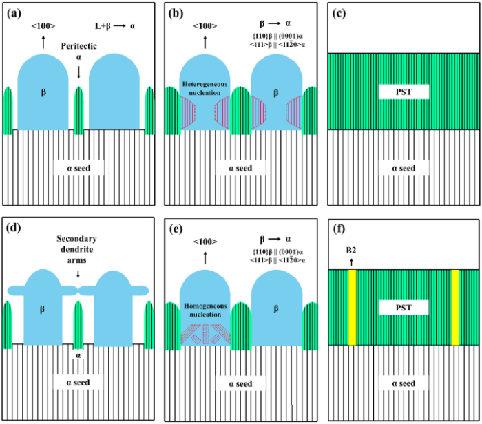
Fig. 7.
Schematic process of a new mechanism on seeding procedure showing (a) nucleation and growth of β phase and peritectic α phase nucleating directly from the melt; (b) β/α transformation in heterogeneous nucleation model, (c) lamellar structure after the whole process; (d) appearance of β secondary dendrites and (e) β/α transformation in homogeneous nucleation model and (f) formation of the columnar B2 phase parallel to the growth direction.
The composition of Ti-46Al-8Nb alloy is on the hypo-peritectic side [23], so a large amount of β phase will remain after the peritectic reaction. These remaining β phase aggregates are surround by the peritectic α phase. As the temperature goes down, the solid-state β to α transformation will take place. According to the Burgers orientation relationship, the <100 > β cells/dendrites will transform into twelve orientation variants which eventually transform into lamellar structure 0° or 45° to the growth direction. For homogeneous nucleation of α phase inside the remaining β phase, the final microstructure will be the mixed type. Growth rate of the seeding process in the present work is rather slow, and it causes a low cooling rate, which is not sufficient for homogeneous nucleation. Therefore, the β to α transformation may come up in the heterogeneous nucleation model. In this situation, the peritectic α phase can act as nucleus and grow into the primary β phase, and then suppress further nucleation of other α variants from β. Eventually, the entire β phase will transform into the 0° orientation variation, as shown in Fig. 7(b). If all the process shown in Fig. 7(a, b) are not interrupted, successful seeding of the whole bar can be realized. Finally, the whole bar will consist of just one α grain, and it will transform into the lamellar structure paralleling to the growth direction, as shown in Fig. 7(c).
The new mechanism proposed in this work can not only explain the results of Ti-46Al-8Nb alloy, but also be applied to other hypo-peritectic alloys. It should be noted that the relatively low growth rate is necessary for successful seeding. As the growth rate increasing, the secondary dendrites of β phase appear, and then obstruct the growth of peritectic α dendrites, as shown in Fig. 7(d). Besides, the higher growth rate causes the higher cooling rate and means higher possibility of homogeneous nucleation, as shown in Fig. 7(e). These two situations are both detrimental for successful seeding and should be avoid in the solidification process. These two situations may be the reason for the failure of the seeding process when the growth rate exceed 30 mm/h.
Nb behaves as a β stabilizer in TiAl systems [9], during the solidification the segregation makes Al rich in liquid and Nb rich in the core of β cells/dendrites. Nb can retard the diffusion process and make the diffusion relevant reaction to occur more slowly. The reaction velocity of solid-state β to α transformation highly depends on the diffusion process, so, the high Nb content in the core of β cells/dendrites could make the transformation occur insufficiency. The residual untransformed β phase (Fig. 5(c)) eventually evolves into B2 phase. The primary β cells/dendrites was aligned to parallel to the growth direction, so, the final B2 phase will follow this morphology and exhibit a final columnar morphology paralleling to the growth direction coexisted with the γ/α2 lamellae (Fig. 7(f)).
3.4. Mechanical properties of Ti-46Al-8Nb PST crystal
The previous published data on mechanical properties of TiAl PST crystals were typically tested from relatively small samples without extensometer, although the reported elongation values of those samples were rather high [[6], [7], [8],11,25,26]. To validate the significant high elongation of TiAl PST crystals, the precise values are required to be measured by the standard tests using large-size specimens. Nevertheless, it is extremely difficult to prepare large-size PST crystals. In the present work, PST crystals of Ti-46Al-8Nb alloy with the dimension of 9 mm in diameter and 70 mm in length were successfully prepared after the new operations. Large-size standard tensile samples (Fig. 2) were machined, and then tested with an extensometer. Mechanical properties of room temperature tensile tests are shown in Table 1. Photo of fractured tensile samples compared with the un-deformed one are shown in Fig. 8(a). Typical engineering stress-strain curves of tensile tests of standard samples are shown in Fig. 8(b).
Table 1 Mechanical properties of room temperature tensile tests.
| Gauge size (mm) | Yield strength (MPa) | Ultimate strength (MPa) | Elongation (%) |
|---|---|---|---|
| Φ4 × 20 | 575 | 630 | 11.9 |
| 582 | 615 | 13.1 | |
| 545 | 613 | 18.5 | |
| Average | 567 | 619 | 14.5 |
Fig. 8.
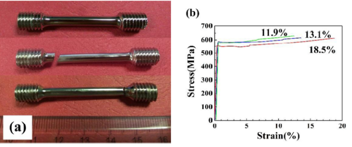
Fig. 8.
(a) Photo of fractured tensile samples compared with the un-deformed one (top) (b) and engineering stress-strain curves of standard samples.
Compared with polycrystalline TiAl alloys, the Ti-46Al-8Nb PST crystals show large advantage in elongation. The average elongation of the large standard samples reaches 14.5%, and this represents an ultra-high elongation for TiAl intermetallic compound. Elongation of one sample even reaches 18.5%, and it is higher than all the other values have ever published.
Although the three samples were prepared and tested in the same routes, there exists a large variance in ductility. During the actual solidification, stray grains are inevitable. As for TiAl PST crystals, these stray grains could cause the local stress concentration and certainly decrease the ductility. Besides, microcosmic defects such as discontinuity of the lamellae may be a potential reason. These unsolved problems will be studied in our next work.
4. Conclusions
In summary, through introducing several new operations, large size PST crystals (Φ9 mm × 70 mm) of Ti-46Al-8Nb alloy with a parallel lamellar microstructure were successfully prepared from the Ti-43Al-3Si seed. The higher growth rate (>30 mm/h) led to the failure of seeding process. A large amount of columnar B2 phase paralleling to the growth direction was found in the final lamellar microstructure of alloys solidified at the lower growth rate (<20 mm/h). A peritectic mechanism was proposed to describe the seeding process. The peritectic α phase was suggest to nucleate directly from the melt, not at the surface of primary β, and then they act as nucleus in the subsequent β to α transformation. At the higher growth rate, appearance of β phase secondary dendrites and homogeneous nucleation inside β phase would lead to the failure of seeding process. High Nb content led to a large amount of residual β phase and these β dendrites finally evolved into B2 phase.
Room temperature tensile tests were conducted on large standard specimens. The results showed that the PST crystals can gain an ultra-high elongation up to 11.9-18.5% before fracturing. This is the highest elongation ever reported for TiAl-based alloys tested from an extensometer.
Acknowledgment
This work was supported by National Natural Science Foundation of China (No. 51701209) and National Key Research and Development Program of China (Nos. 2016YFB0701304). Authors acknowledged Weisheng Tan for preparing the button ingots and Dingrui Ni for conducting the tensile tests.
Reference

 WeChat