

1. Introduction
Inconel 718, a Ni-Cr-Fe austenite high-temperature alloy, is one of the most widely used candidates in the nickel based superalloys family, which keeps its face-centered cubic (fcc) crystal structure from ambient temperature throughout to its high melting temperature of about 1300 °C [1,2]. It is characterized by an improved balance of high strength, creep performance, tensile property, as well as superior corrosion and oxidation resistances at elevated temperatures up to 700 °C, thus are attractive using as the structural materials for many critical high-temperature situations (including as critical components in liquid fueled rockets, rings, aircraft and land-based gas turbine engines) [3]. However, during recent years, the increasing demands for high performance nickel-based superalloys have been put forward to satisfy the requirement of higher speed and thrust to weight ratio for advanced aerospace engines [4]. It is actually a great challenge for Inconel 718 superalloy, which hence hinders its further applications in aerospace industry branches.
The filler of hard and stiff ceramic particles into metal matrix to form a composite (MMCs) may offer materials the higher hardness, wear resistance, and superior mechanical properties while maintain the necessary ductility compared to the counterpart of matrix materials [5]. In this regard, tremendous efforts on ceramic particles reinforced Inconel series alloys have been made. The results revealed that the high-temperature mechanical behavior [6,7], hot corrosion property [8,9], and wear resistance [10,11] of MMCs were enhanced considerably by virtue of the unique attributes of ceramic reinforcement, e.g. high modulus, high melting point, high hardness, and anti-oxidization. As is well known, the strength of MMCs are usually governed by particle size, distribution as well as the bonding state of matrix-reinforcement interfaces [12,13]. The formation of ultrafine and stable ceramic reinforcements was expected to exhibit superior mechanical properties than the coarse counterpart, which, as well, contributed to the more excellent interface bonding with matrix. However, in term of conventional dispersion-strengthened composites by ex situ methods, the carbide particles usually tend to segregate at grain boundaries (GBs) and form coarse particulate, which brought about stress concentration at GBs and hence lead to the early intergranular fracture [14]. This drawback can be compensated by in-situ route. The in situ formed reinforcing particles are finer in size and their distribution in the matrix is more uniform [15].
During recent years, using Mn+1AXn phases (M is an early transition metal, A is an A-group element, and X is carbon and/or nitrogen) as precursor to in situ transform into TiC particulate has aroused many attention of material researchers in term of reinforcing metal matrices (Cu [16,17], Fe [18,19], Ni [20,21]). In addition, by exfoliating the internal Al atoms of Ti3AlC2 using HF, an edge of a new scientific frontier material, two-dimensional, similar to graphene, Ti3C2 layers-MXene was discovered [22,23]. Titanium aluminum carbide (Ti2AlC) is one of the most attractive ternary carbides in the MAX phase family, performing not only high strength, hardness and modulus like ceramics, but also high electric and heat conductivity, damage tolerance like metals [24,25]. Like other MAX phase materials (Ti3AlC2, Ti3SiC2, Cr2AlC etc.), the instability of the Ti2AlC crystal lattice tends to prompt Al and segmental Ti atoms out of the frame due to the weak bonding between Al and Ti6C layers. In view of our preliminary investigation, due to strong affinity between Ti-Al and Ni, Al-Ti atoms were de-intercalated readily from Ti2AlC matrix and then diffused into Ni matrix, resulting finally in the formation of TiC particulate [[26], [27], [28], [29]]. However, as for the widely used In718 superalloy, the strengthening effect and mechanism by introducing MAX to give rise to in-situ TiC particulate is unclear. The related publications up to date are also quite scarce.
Herein, in the present work, an ultrafine TiC-reinforced In718 matrix composites was fabricated by introducing Ti2AlC as precursor. The objective of this experiment is to probe the interfacial microstructure between TiC and In718 matrix and determine the mechanical behaviors at both room and high temperatures. The three prominent features of the present investigations are as following: (i) analyzing reaction mechanism, phases constitution and particulate distribution of in-situ TiC/In718 composites with different content of Ti2AlC; (ii) characterizing the interfacial bonding between TiC and In718 using high resolution electron microscopy; (iii) evaluating the room and high temperature tensile properties of these novel composites in comparison with monolithic In718 processed by the same method.
2. Experimental details
2.1. Preparation of materials
A gas-atomized and spherical Inconel 718 powder (-300 mesh, AMC POWDERS, Beijing, China) (Fig. 1(a)) and a homemade flake-shaped Ti2AlC powders with the particle size distribution 3-11 μm (Fig. 1(b)) were used as the starting materials. The nominal chemical compositions of Inconel 718 powder are listed in Table 1. The details of synthesis of Ti2AlC powder was described elsewhere [25].
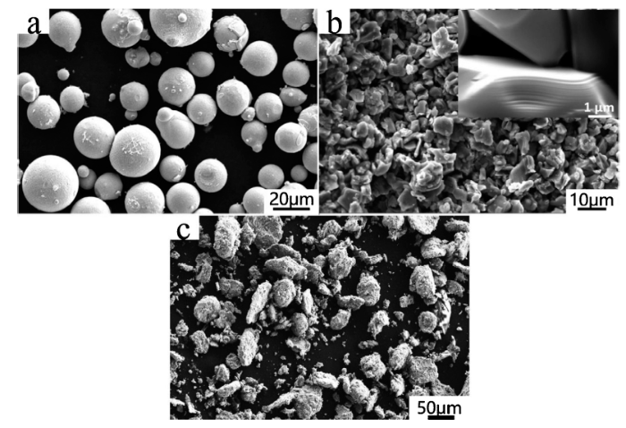
Fig. 1.
Typical morphologies of the starting In718 powder (a), Ti2AlC precursor particles (b), and the uniformly blended Ti2AlC/Inconel 718 composite powder by plenary milling (c).
Table 1 Nominal composition of In718 alloy.
| Ni | Fe | Cr | Nb | Mo | Ti | Al | C | S |
|---|---|---|---|---|---|---|---|---|
| Balance | 18.63 | 17.65 | 4.79 | 3.07 | 0.86 | 0.6 | 0.04 | 0.03 |
2.2. Composites preparation procedures
The composite powders containing 5 vol.%, 10 vol.% and 15 vol.% Ti2AlC/In718 (labeled as 5TAC/In718, 10TAC/In718 and 15TAC/In718) were prepared by high energy ball milling in a QM-3SP4 planetary mono-mill (Nanjing NanDa Instrument Plant, China), respectively, with a ball-to-powder weight of 5:1. The milling process was conducted for 10 h at a rotation speed of 300 rpm. The image of as-resulted composite powders was presented in Fig. 1c. The composite powders were then poured into the h-BN coated cylindrical graphite die with sectional dimension of 25 mm × 36 mm, and then consolidated by hot pressure sintering technique. Specifically, the starting powders was firstly heated to a sintering temperature of 1200 °C at the rate of 10 °C/min with a holding time of 1 h (ZT-30-22Y, Chenhua, China). The pressure of 5 MPa was then applied to ensure constant contact of die-punch system. Furthermore, the pressure was gradually increased from 5 to 25 MPa at the onset of 10 min dwelling at 1200 °C. After a soaking time of 1 h, the bulk specimen was furnace cooling to 500 °C and then released the pressure. The fabricated composite was finally taken out as the furnace temperature dropped to 80 °C. For comparison, the pure In718 was also prepared under identical procedures. Afterwards, the fabricated specimen was subjected to a heat treatment process in an electrically heated tube furnace (TSK-5-14, FNS, Beijing). The heat treatment processes for monolithic In718 and TiC/In718 composites were firstly solid solution at 1020 °C for 1 h, and then water cooling. The aging treatment was conducted by two-steps. At first, the sample was holding at 720 °C for 8 h, and then cooling down to at the rate of 50 °C/h. After soaking for 8 h at 620 °C, the samples were taken out for air cooling. The heat treatment process can be also simplified as 1020 °C, 1 h/WC + 720 °C, 8 h/FC (50 °C /h) to 620 °C, 8 h/AC.
2.3. Microstructural characterization
The phase constitution and crystal structure were identified by X-ray diffractometer (XRD) using CuKα radiation (X0 PERT-PRO MPDT, Netherlands). The microstructure was analyzed by scanning electron microscope (SEM, ZEISS EVO18, Germany) and a transmission electron microscope (TEM, FEI Tecnai G2 F20). The average diameter size of particles was measured by Nano Measurer software. To ensure accuracy, over 200 particles were measured in different fields. The samples for transmission electron microscope (TEM) investigation were mechanically ground, polished and dimpled to about 50 μm, and then ion-beam milling using a Gatan Precision Ion Polishing System (PIPS, Gatan model 691). The tensile tests of composites were performed on a WDW-100E (Shijin, Jinan, China) testing machine equipped with high temperature furnace (GW-1200, Fangrui, China). Sheet dog bone-shaped tensile specimens were machined from as-resulted discs. The parallel length of tensile specimen was 8 mm, and the cross-sectional dimension was 2 mm × 1 mm. A high temperature tensile tests was performed at temperatures of 600 °C, 700 °C, 800 °C and 900 °C at a strain rate of 1 × 10⁻³ s-1. Before deformation, the specimens for tensile tests were heated to the setting temperatures at the rate of 10 °C/min and soaked for 5 min to reduce the thermal gradient. After fracture, the specimens were immediately took out from the furnace and then put them into water to obtain the original features of fracture morphologies.
3. Results and discussion
3.1. Phase constitution
The typical XRD patterns of Ti2AlC and In718 raw materials and fabricated TiC/In718 composites with different Ti2AlC additions after heat treatment are presented in Fig. 2. From the diffraction pattern of Fig. 2(a) corresponding to Ti2AlC materials, there are traces of Ti3AlC2 formation in the matrix. As a precursor of resulting TiC particles, the effect of Ti3AlC2 impurity can be ignored as it can also be decomposed to TiC eventually in the high temperature. In the monolithic In718 sample shown as pattern b, the strong diffraction peaks of (111), (200), (220) corresponding to typical face-centered cubic γ (Ni-Cr-Fe) matrix can be clearly identified. In the TiC/In718 composite corresponding to the diffraction pattern c, d and e, the presence of some relatively weak peaks at the 2θ of 35.8° and 41.9° were detected, which were matched with TiC reinforcing phase. There are no traces of Ti2AlC in the matrix, indicating the complete decomposition. Besides, there were no new phases observed in XRD patterns of fabricated composites within the limitation of XRD detection, hence a final in-situ TiC/In718 composite was formed. Furthermore, from the elarged range of about 43°-45° (2θ), the 2θ locations of diffraction peaks for γ-Ni phase shifted to lower 2θ angles in the sample with the increment of Ti2AlC contents from 0 to 15 vol.%. According to the Bragg's formular [30]:
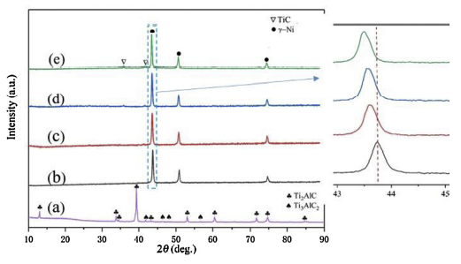
Fig. 2.
XRD patterns of starting materials and fabricated TiC/Inconel 718 composite parts: (a) Ti2AlC powders; (b) In718 powders; (c) 5TAC/In718; (d) 10TAC/In718; (e) 15TAC/In718.
The 2θ displacement shifting to lower Bragg angles indicated an increase of adjacent lattice planes distance (d), which, can be ascribed to the distortion of lattice due to the incorporation of entire Al and partial Ti atoms derived from Ti2AlC phases into the γ-Ni matrix lattice. In order to further illustrate the influence of Ti2AlC on diffraction peaks for γ-Ni in the composites, the determination of 2θ displacement and corresponding distance of lattice planes of γ-Ni phase are quantitatively measured, as listed in Table 2.
Table 2 XRD data showing displacement and inter-planar spacing variations of the peaks corresponding to (111) and (200) of γ phase.
| Samples | (111) lattice plane | (200) lattice plane | ||
|---|---|---|---|---|
| 2θ (deg.) | d(111) | 2θ (deg) | d(200) | |
| In718 | 43.772 | 2.0665 | 50.901 | 1.7922 |
| 5TAC/In718 | 43.625 | 2.0729 | 50.712 | 1.7986 |
| 10TAC/In718 | 43.574 | 2.0752 | 50.701 | 1.7989 |
| 15TAC/In718 | 43.521 | 2.0775 | 50.623 | 1.8015 |
3.2. Microstructure analysis
The microstructures of TiC/In718 composite with different content of Ti2AlC were investigated. Fig. 3(a) and (b) presents the SEM images of 5TAC/In718 composite after sintering and subsequent heat treatment, in which, the ultrafine TiC reinforcing particulates transformed from Ti2AlC were homogenously distributed in the interior and boundary of columnar In718 grains. The size distribution of the TiC particles was also analyzed. A SEM image of the in-situ formed TiC particle and the corresponding particle size distribution are shown in Fig. 4. Fig. 4(b) exhibits a histogram of the TiC diameter based on 200 particles. It can be noted that the TiC particle size ranges from a few nanometers to ∼700 nm in diameter with the average diameter of ∼230 nm. The similar microstructural characteristics are also presented in the 10TAC/In718 composite. The uniform dispersion of nanoparticles in the matrix provides convincing evidence that TiC particles were previously well dispersed and selfstabilized in the In718 matrix. However, in the 15TAC/In718 composite, TiC particulate were flock together along the grain boundary of In718 due to attractive van der Waals forces between ultrafine particles. Previous studies revealed that a higher drag force in the melt via dense nanoparticles (for example, >6 vol.%) could promote nanoparticle engulfment [31]. Typically, a lower volume fraction of nanoparticles can be more uniformly dispersed in the matrix. The coarse particulates tended to more distribution on the grain boundary. As Liu et al. [5] reported that in the La2O3 reinforced Mo alloy composite, most of the nanoscale La2O3 (average ∼80 nm) homogeneously dispersed in the grain interior, while the coarse counterpart (average ∼230 nm) are predominantly distributed at grain boundaries. Specifically, in 15TAC/In718 composite, de-intercalated TiC particles segregate at GBs and grow into stripe after high temperature sintering. The coarse TiC particles at GBs would not only cause stress-concentration and decrease the ductility, but also reduce the strengthening effects.
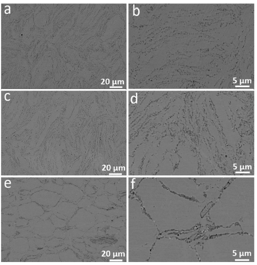
Fig. 3.
Microstructures of as-prepared composites: (a, c, e) surface microstructures of 5TAC/In718, 10TAC/In718 and 15TAC/In718 in BSE mode; (b, d, f) higher magnification microstructure in (a, c, e), respectively.
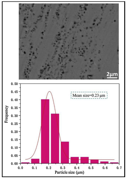
Fig. 4.
SEM image of (a) the in-situ formed TiC powder in 5TAC/In718 composite and the statistical result showing (b) the corresponding particle size distribution.
Fig. 5 presents a representative TEM image of the 5TAC/In718 composites. Fig. 5(a) shows that the nano-TiC particulates labeled as solid white arrows distributed in the grain interior of In718 matrix. The internal TiC could not only refine the grain size of matrix due to the heterogeneous nucleation but also efficiently hinder the dislocation motion [17]. The EDS analysis in TEM mode were moreover conducted on the TiC particulates. The result can be found in Fig. 6. From the image, it can be noted that few Nb element existed in the TiC particles. In theory, substoichiometric ratio of C/Ti should be 0.5∼1 due to the de-intercalation of enough Al and Ti atoms from Ti2AlC. The atomic ratio of the C element and Ti + Nb in this work was almost 1:1. Therefore, it can be deduced that the localized Ti and C atoms reacted with Nb elements from In718 at high temperature, few Nb atoms substituted some Ti atoms in the substoichiometric TiC, hence brought about the in-situ formation of (Ti,Nb)C carbide reinforcing phase throughout the matrix. In addtion, in the γ-Ni solution matrix, there is also a recognisable long-strip phase. According to the diffraction pattern of In718 matrix (Fig. 5(b)), the superlattice pattern corresponding to nano-scale γ´´-Ni3Nb (D022 crystal structure) and γ´- Ni3(Al,Ti) (L12 crystal structure) was identified. In the bright field mode, the γ´´ phase is recognizable, however, the morphology of γ´ phase is difficult to be detected, this may be due to the superimposing effect of γ´´phase [6]. Fig. 5(d) shows the intergranular nano-TiC particulates on the grain boundary of In718 alloy. The interfacial bonding between TiC particle and matrix corresponding to the rectangle in Fig. 5(d) is shown in Fig. 5(e). The clean interface without any reaction product or impurities can be observed by HRTEM image. The analogous result was also appeared in the in-situ TiC0.5/Cu composite using Ti2AlC as precursor [15]. The in situ formed substoichiometric TiC perform superior interfacial bonding with Cu-Al matrix, which thus endowed the TiC0.5/Cu-Al composite better mechanical properties than ex situ TiC/Cu composite. Fig. 5(f) presents the FFT image of boxed area in Fig. 5(e). The diffraction spots circled in Fig. 5(f) were used to reconstruct an inverse FFT image as shown in Fig. 5(g). There are a few of dislocations can be identified in the matrix approaching to the TiC side, which was marked by white “T”. Owing to the discrepancy of thermal expansion coefficients between soft matrix and stiff reinforcements, the mismatch strain was usually generated in the ceramic particles reinforced metal matrix composite as the composite is cooled down from the synthesizing temperature. Therefore, a lot of dislocation loops are formed adjacent to the interface.
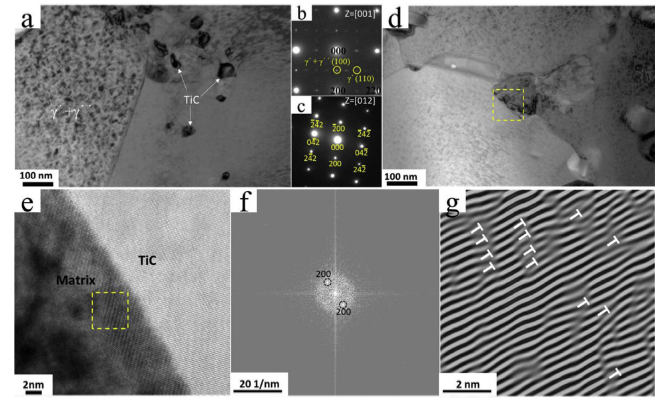
Fig. 5.
(a) Bright field image of 5TAC/In718 composite showing nano-TiC distribution in the interior of matrix, (b, c) the corresponding diffraction patterns of In718 matrix and TiC phases, (d) bright field image of 5TAC/In718 composite showing nano-TiC distribution on the boundary of matrix, (e) HRTEM image of the interface between TiC particle and matrix, (f) the corresponding FFT patterns of yellow frame in (e), (g) the inversed FFT image of (f).
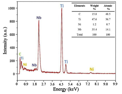
Fig. 6.
EDS result of in-situ formed TiC particulate in In718 matrix corresponding to
3.3. Mechanical properties
The engineering stress-strain curves of fabricated samples and comparison of tensile performance with the counterpart of In718-series composite and other alloys are shown in Fig. 7. An enhanced strength of about 1410 MPa while retained a 9.8% and 7.8% of elongation is achieved by the addition of 5 and 10 vol.% Ti2AlC, respectively. However, in 15 vol.% Ti2AlC/In718 composite, the tensile behavior was weakened. The decreased strength and elongation can be ascribed to the cluster of TiC on the grain boundary of In718 matrix, which cause stress-concentration and decrease the ductility. The collective data of Inconel-series composite and other alloys shows clear strengthening trend with as-fabricated TiC/In718 composite, as shown in Fig. 7(b). Compared with the reported countpart, the present TiC/In718 composites exhibited a better performance in the room temperature. The present approach provides an effective route for fabricating Ni-matrix composites reinforced with in-situ TiC particulate, and the excellent mechanical properties make TiC/In718 composite a potential candidate for high-performance structural applications in automobile and aerospace industry branches.
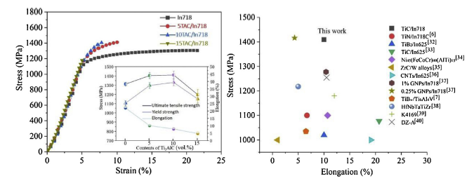
Fig. 7.
(a) Engineering stress-strain curves and tensile performance comparison (inset) of processed In718 samples with different volume of Ti2AlC particles and (b) ultimate tensile strength versus specific elongation of prepared TiC/In718 composite (5 vol.% Ti2AlC) in comparison with the results from other Inconel-series composite and alloys [[32], [33], [34], [35], [36], [37], [38], [39], [40]].
The high-temperature tensile properties determination of TiC/In718 (5 vol.% Ti2AlC) were conducted in the range from 600 to 900 °C, while the tensile properties of In718 superalloy were also measured for comparison. Fig. 8 shows the stress-strain curve of TiC/In718 composite and In718 superalloy and their yield strength (YS) and ultimate tensile strength (UTS) comparison in the high temperature. For both In718 alloy and TiC/In718 composites, the tensile strength decreased with the increasing temperature of tests. However, the UTS of composite was always higher than In718 superalloy together with the competent elongations as structural material. The YS and UTS of the TiC/In718 composite at 600 °C was determined to be 1219 MPa and 1334 MPa, which is 15.2% and 9.4% higher than that of In718 superalloy, respectively. When the testing temperature increases to 700 °C, the YS and UTS of the TiC/In718 composite decreased to 930 MPa and 1010 MPa, which is also approximately 19.2% and 14.6% higher than that of the monolithic In718 sample. Furthermore, it should be noticed that the UTS and YS at room temperature and 700 °C of TiC/In718 composite prepared by reactive hot-press sintering are superior to those of the investment casting TiN/IN718C composite. The YS and UTS of TiN/IN718C composite under 700 °C is about 884 MPa and 912 MPa with the limited fractural elongation of 3.3% ± 1.4% [6].
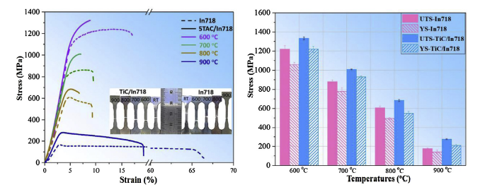
Fig. 8.
(a) Engineering stress-strain curves of processed In718 samples and TiC/In718 composite at high temperature and (b) tensile performance comparison.
The typical fracture surface morphologies of fabricated In718 alloy and TiC/In718 composites (5-15 vol.% Ti2AlC) at room temperature is shown in Fig. 9. The low magnification micrographs corresponding to left hand (Fig. 9(a, c, e and g) revealed the general overview of fracture surface, while the high magnification characterization in the right hand showed the typical fractural features (Fig. 9(b, d, f and h). In the ductile In718 alloy, a large amount of deep and refined dimples together with little intergranular cracks were present on the fracture surface (Fig. 9(b)). In the fabricated 5 and 10 vol.% Ti2AlC/In718 composite, many cone-shaped dimples and tear ridges along the columnar matrix grain were observed on the fracture surface, suggesting a considerably plastic deformation occurred before fracture. In addition, the rough fracture surface of 10 vol.%Ti2AlC/In718 composite containing some parallel grooves can be also clearly noted, and the width of these grooves is consistent with the grain sizes of TiC. This indicates that the relative sliding occurred between two fracture surfaces during necking in the tensile process, which thereby resulted in the local area plowed by stiff TiC particulate. This, from other hand, suggests the well-contacted interfaces existing between in-situ TiC formation and In718 alloy. Contrastingly, in the 15 vol.% Ti2AlC/In718 composite, the facture surfaces are flat, exhibiting the characters of brittle fracture. The interface between TiC clusters and matrix debonds, some strip-like TiC (Fig. 9(h)) were pulled out from the matrix, leaving some holes and cracks in the matrix.
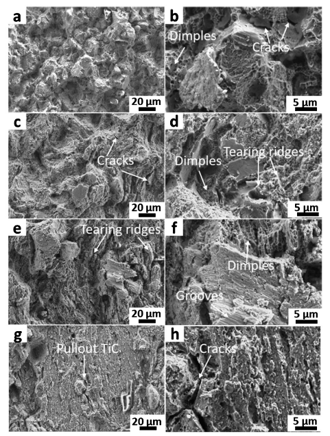
Fig. 9.
Fractural morphologies of as fabricated In718 alloy (a, b) and 5TAC/In718 (c, d), 10TAC/In718 (e, f) and 15TAC/In718 (g, h) composites at low (a, c, e, g) and high (b, d, f, h) magnification after tensile test at room temperature.
The representative fractural tensile morphologies of In718 alloy and TiC/In718 composite under 700 °C were presented in Fig. 10. It can be seen from In718 alloy (Fig. 10(a)) that the main crack follows the adjacent grain boundaries, i.e., fracture occurred through the intergranular grains. However, a different fracture feature of TiC/In718 composite can be identified. As seen from Fig. 10(c) and (d), there are a large matrix tear ridges and refined dimples, which demonstrates prominent toughening mechanism. The rather rough fracture surface and intragranular mode in matrix indicates a hard crack propagation path due to the pinning effect of TiC particulate, which is similar to the fracture features in the room temperature. The in-situ formation of TiC particles in In718 matrix exhibit well-bonded interfaces without foreign impurity, which is beneficial to the effective load transference from In718 matrix to TiC phase.
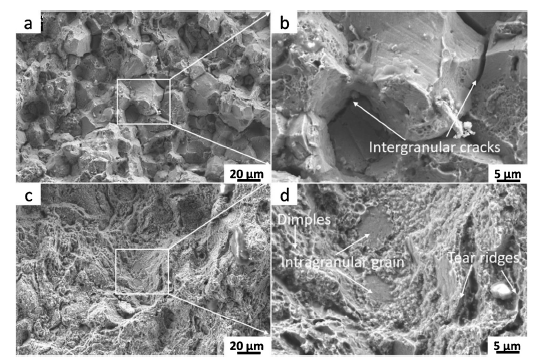
Fig. 10.
Fractural morphologies of as fabricated In718 alloy (a, b) and TiC/In718 (c, d) composites at low (a, c) and high (b, d) magnification composites after tensile test at 700 °C.
3.4. Strengthening mechanism
In the general particle reinforced metal matrix composites, many theoretical models have been put forward to predict the strength of particle-reinforced metal matrix composites (MMCs) [31]. The strengthening effect induced by ceramic particles is usually the result of several combined mechanisms including continuum models and micromechanical models [6].
Before analyzing the strengthening mechanism of TiC/In718 composite, a specific phase constitution evolution in the Ti2AlC-In718 system should be illustrated. In the In718 superalloys, Nb is the vital element contributing to the formation of γ´´ phase [3]. The concentration of Nb in the matrix was slightly declined due to the replacement of Ti in the TiC phase, which would bring about a few decrease in volume fraction of the aging precipitated γ´´ phase in TiC/In718 composite. However, the replaced Ti atoms by Nb together with overall Al entered the matrix, therefore it can be inferred that the coherent strengthening effect of γ´´ phase can be compensated by γ´ phase increment due to the slightly increment of Al-Ti concentration in matrix. In addition, considering that no fine intermetallic precipitates were observed in TiC/In718 samples, the strengthening mechanism must be mainly caused by the uniformly dispersed carbide particles. It was deduced that the strengthening effect of fine TiC precipitates in the TiC/In718 might be attributed to three factors: (1) Increased dislocation density due to mismatch of thermal expansion coefficient; (2) Dispersion strengthening of hard TiC particles (Orowan mechanism); (3) load bearing mechanism.
The total yield strength enhancement induced by dispersed TiC particulate in the 5 vol.% Ti2AlC/In718 samples is about 160 MPa. From the TEM analysis (Fig. 5(g)), there are lots of dislocations in the matrix adjacent to the interface between matrix and TiC. The contribution to the strengthening from the increased dislocation density should be ascribed to the mismatch of thermal expansion coefficient between TiC (CTE = 7.6 × 10⁻⁶ °C-1) and In718 (CTE = 13 × 10-6 °C-1). The previous investigations showed that the metal matrix composites (MMCs) have usually higher dislocation density than alloy due to the mismatch between heterogeneous particles and matrix [14]. The similar phenomenon has also been revealed by Wang et al. about TiN particles reinforced IN718C composite, in which, a large amount of geometrically necessary dislocations accumulated near the interface between TiN and In718C after plastic deformation. The geometrically necessary dislocations contributed to the prominent strengthening effect for the TiN/In718C composite [6]. The strengthening effect of enhanced dislocation density on the mechanical properties of materials can be described according to the following model:
where Vp, ΔT, ΔC, b and dp are the volume fraction of TiC particulates, temperature variation from heat treatment to the ambient temperature, misfit of the thermal expansion coefficient between TiC and the matrix, Burger's vector of matrix, and mean size of the TiC particulates, respectively. Considering 5 vol.% Ti2AlC/In718 composite that in this study Vp = 0.036, ΔT = 600 °C, ΔC = 5.4 × 10⁻⁶ °C-1, b=0.32 nm [26], and dp = 250 nm, the calculated ρ = 18 MPa.
In addition, when the TiC/In718 composite deformed plastically, the dislocation lines are enabled to directly cut through the second phase [[41], [42], [43]]. Therefore, the dislocation motion was hindered, increasing the sliding force. The contribution of Orowan strengthening (Δσ Orowan) mechanism induced by well dispersed particles to the enhancement of mechanical properties can be calculated in the following equation [31]:
The rest of strengthening contribution is due to the load bearing mechanism. The increase in strength due to load bearing can be calculated by the following equation [17]:(4)Δσload = 1.5Vpσiwhere σi is interfacial bonding strength. For the sake of obtaining a balance of strengthening contribution of 41 MPa, the interfacial strength σi should be around 740 MPa. This result indicates a very strong interfacial bonding between TiC particles and In718 matrix, as we observed from the TEM analysis in Fig. 5.
4. Conclusions
In this study, an in-situ TiC/In718 composite and comparison of Inconel 718 alloy processed by reactive hot-pressing sintering were investigated. The main conclusions can be drawn as follows:
(1)During high temperature, the melt In718 triggered de-intercalation of Ti2AlC, which leading to the formation of in-situ ultrafine TiC particulates distributed uniformly in the matrix. The in-situ TiC particles offer the well-compacted interface between In718 matrix.
(2)The prepared TiC/In718 composite exhibit excellent room and high temperature mechanical properties. The higher ultimate tensile strength of 1410 MPa was obtained in TiC/In718 composite (5 vol.% Ti2AlC) at room temperature. At 700 °C, the YS and UTS of the TiC/In718 composite decreased to 930 MPa and 1010 MPa, which is also approximately 19.2% and 14.6% higher than that of the In718 superalloy.
(3)The strengthening effect with the formation of ultrafine TiC precipitates in the TiC/In718 could be attributed to the combined mechanisms in term of increased dislocation density, Orowan strengthening and the effect of load bearing.
Reference

 WeChat