

1. Introduction
Carbon aerogels (CAs) are expected to have a wide range of applications, such as hydrogen storage, catalyst supports and electrodes for double layer capacitors [[1], [2], [3], [4], [5]]. Moreover, CAs are promising thermal insulation materials for thermal protection system of spacecraft due to their low density, low thermal conductivity, high specific extinction coefficient and high thermal stability at temperature of over 2000 °C [[6], [7], [8]]. However, the applications of CAs in thermal insulation fields have often been limited by their poor mechanical properties and large-size forming abilities [[9], [10], [11], [12]]. Besides, the conventional CAs synthesis methods are costly and time-consuming and thus severely restrict their commercialization [[13], [14], [15], [16]].
The traditional methods for CAs preparation typically include four steps: sol-gel polymerization of reagents, solvent exchange, drying, and carbonization. Among these, solvent exchange and drying are two key steps in which solvent (usually deionized water) is removed from wet gels while maintaining their structural integrity and high porosity. The solvent exchange is fussy due to repetitive substituting procedure over 10 times, and thus is time-consuming, expensive and less environment-friendly [17,18]. Only a few efforts have been made to further simplify the preparation process based on the elimination of solvent exchange. In 1999 and 2001, Qin et al. [19,20] developed an alcoholic-sol-gel polymerization method by using alcohol as solvent. In 2002, Lee et al. [21] described a surfactant-templated sol-gel polymerization method by adding cetyltrimethylammonium bromide (CTAB) as surfactant. In 2006 and 2008, Wu et al. [22,23] reported a microemulsion-templated sol-gel polymerization method through addition of CTAB as surfactant. In these methods, an insufficient polymerization reaction was possibly proceeded since the alcoholic solvent cannot produce ions in the ionic reaction [22] and the surfactant can consume the reaction sites [23], which results in an adverse effect on the mechanical properties of the synthesized CAs.
After the solvent exchange, supercritical drying is often used to dry the wet gels in order to maximize the maintenance of their original microstructure since it has almost zero surface tension [24]. However, the requirements of high temperature and pressure make supercritical drying a costly and even dangerous preparation procedure [14,25]. Therefore, ambient pressure drying has been considered to be a promising method for the further commercialization of CAs. Some works on the preparation of CAs through ambient pressure drying have been reported, but the prepared samples exhibited poor mechanical properties and undesirable monolithic forming abilities [[13], [14], [15],22,[26], [27], [28], [29]]. These results could be attibuted to the large surface tension caused by ambient pressure drying, which can induce pore collapse due to their relatively weak network strength. Consequently, solvent exchange is generally considered to be a compulsory process for ambient pressure drying since the surface tension of water (γ = 72 × 10-3 N m-1) is about 3 times higher than those of organic solvents, such as ethanol (γ = 22 × 10-3 N m-1), acetone (γ = 24 × 10-3 N m-1) and cyclohexane (γ = 26 × 10-3 N m-1) [[30], [31], [32], [33], [34]].
It is well-known that reduction of surface tension and improvement of skeleton network strength are two key approaches for the fabrication of CA monoliths. The above-mentioned studies paid main attention to decrease the surface tension by using the alcohol solvent or adding the surfactant. As far as we know, there are only few literatures focused on improving the organic network to resist pore shrinkage/collapse during ambient pressure drying with solvent exchange [11].
In this work, the strong CA monoliths were prepared through polycondensation of resorcinol with formaldehyde by adding sodium carbonate and deionized water as catalyst and solvent, respectively, then followed by ambient pressure drying without solvent exchange, and carbonization. The microstructures of CAs were tailored by adjusting catalyst concentration, water content and gelation temperature in order to obtain high skeleton network strength. The porosity parameters, drying and carbonization shrinkages, bulk densities, mechanical properties and thermal conductivities of CAs were investigated.
2. Experimental
2.1. Synthesis
In this work, resorcinol, formaldehyde, sodium carbonate and deionized water were referred as R, F, C and W, respectively. The detailed synthesis parameters are listed in Table 1. The molar ratio of R/F was fixed at 0.5. According to the method, the solutions, containing R, F, C and W, were mixed by a magnetic stirrer at room temperature and then decanted into glass molds: vials (Φ15 × 30 mm) or tanks (200 × 200 × 40 mm). Then the molds were sealed in order to prevent evaporation of W and oxidation of R during preparation. After that, the solutions were heated in a water bath at predetermined gelation temperatures (Table 1), and then the resulting hydrogels were further cured in the water bath at 90 °C for 2 days. After curing, the hydrogels were directly dried in air at room temperature for 3 days or an appropriately extended time according to the sample dimensions. Especially, for large-sized samples, the hydrogels were firstly brushed with resin glue at the edges to reduce uneven drying and prevent cracking in the subsequent drying step. Afterwards, the samples were further dried in an oven at 90 °C for about 2 days. At last, the samples were carbonized at 900 °C for 2 h with a heating rate of 1 °C/min in flowing Ar atmosphere. The resulting organic aerogels and carbon aerogels were labeled as OAs-xx and CAs-xx, respectively, where the xx is the sample number. Additionally, a type of CAs (named as CAs-xx*), which underwent a successive process of ethanol solvent exchange, ambient pressure drying and carbonization, were also prepared as reference materials.
Table 1 Synthesis parameters and properties of OAs and CAs.
| Samples | R/C | W/R | Tgel (°C) | DS (%) | ρOA (g/cm3) | CS (%) | ρCA (g/cm3) | σCA (MPa) | ECA (MPa) |
|---|---|---|---|---|---|---|---|---|---|
| A1 | 300 | 17 | 30 | 29.21 | 0.92 | 23.14 | 1.13 | 126.8 | 1981.3 |
| A2 | 500 | 17 | 30 | 22.93 | 0.71 | 19.87 | 0.80 | 84.3 | 1170.8 |
| A3 | 1000 | 17 | 30 | 15.94 | 0.49 | 18.92 | 0.54 | 27.1 | 451.7 |
| A4 | 1500 | 17 | 30 | 6.54 | 0.38 | 17.75 | 0.37 | 10.8 | 156.5 |
| A5 | 2000 | 17 | 30 | 3.48 | 0.31 | 17.39 | 0.30 | 6.5 | 135.4 |
| B1 | 300 | 24 | 30 | 35.73 | 0.96 | 23.63 | 1.12 | 147.4 | 2076.1 |
| B2 | 500 | 24 | 30 | 30.15 | 0.73 | 20.55 | 0.82 | 124.4 | 1574.7 |
| B3 | 1000 | 24 | 30 | 22.16 | 0.49 | 18.04 | 0.51 | 39.6 | 545.7 |
| B4 | 1500 | 24 | 30 | 13.70 | 0.37 | 17.64 | 0.36 | 8.9 | 120.3 |
| B5 | 2000 | 24 | 30 | - | - | - | - | - | - |
| C1/A5 | 2000 | 17 | 30 | 3.48 | 0.31 | 17.39 | 0.30 | 6.5 | 135.4 |
| C2 | 2000 | 17 | 45 | 8.92 | 0.42 | 19.08 | 0.40 | 11.5 | 169.4 |
| C3 | 2000 | 17 | 60 | 10.63 | 0.43 | 18.94 | 0.42 | 21.4 | 270.6 |
| C4 | 2000 | 17 | 75 | 11.86 | 0.44 | 18.17 | 0.46 | 29.1 | 323.8 |
| C5 | 2000 | 17 | 90 | 14.92 | 0.46 | 17.64 | 0.47 | 38.2 | 502.6 |
| C3* | 2000 | 17 | 60 | 10.35 | 0.41 | 18.35 | 0.42 | 22.3 | 258.7 |
| C5* | 2000 | 17 | 90 | 14.18 | 0.47 | 16.63 | 0.45 | 35.4 | 481.9 |
Note: R/C: molar ratio of R to C, W/R: molar ratio of W to R, Tgel: gelation temperature, DS: drying shrinkag, ρOA: bulk density of OAs, CS: carbonization shrinkage, ρCA: bulk density of CAs, σCA: compressive strength of CAs, ECA: compressive modulus of CAs.
2.2. Characterization
The drying and carbonization shrinkages were calculated by measuring the diameter of each cylindrical sample before and after drying and carbonization, respectively. The bulk densities were determined through dividing weight by volume. The chemical structures of OAs were investigated by solid-state 13C-NMR (Bruker AVANCE III 400 WB) and Fourier transform infrared spectroscopy (Bruker TENSOR 27). The morphologies of CAs were characterized by scanning electron microscopy (SEM, FEI Nano 430) and transmission electron microscopy (TEM) (JEOL JEM 2010HR). The porosity parameters of CAs were measured based on their nitrogen adsorption-desorption isotherms (ASAP 2020 micromeritics). Before the measurements, the samples were degassed in vacuum at 150 °C for 8 h. The specific surface area, micropore surface area and mesopore surface area were calculated based on Brunauer-Emmett-Teller (BET), t-plot and Barrett-Joyner-Halenda (BJH) theories, respectively [[35], [36], [37]].
The mechanical properties of CAs were tested by compression experiments using an electron universal testing machine (SANS CMT 5205) with a deformation velocity of 1 mm/min. The samples were made into cylinders with a size of about Φ10 × 15 mm. The corresponding stress-strain curves were recorded in order to get the compressive strength and modulus. The thermal conductivities of CAs were measured at 25 °C through a transient hot-wire method (XIATECH TC3000). The samples for thermal conductivities tests were cut into batten-shape with a size of 30 (length)×10 (width)×10 (height) mm.
3. Results and discussion
3.1. Effect of catalyst concentration (R/C) on microstructures, bulk densities and mechanical properties of CAs
In this work, the CAs with a wide range of R/C from 300 to 2000 were prepared, and the resulting samples were labeled as group A (Table 1). Fig. 1 shows the SEM images of CAs-A1∼A5, which correspond to a R/C of 300, 500, 1000, 1500 and 2000, respectively. It can be seen from these images that the particle size and pore diameter of CAs increase significantly with the rise of R/C. At the R/C value 300, the carbon particles pile up so densely that its pore structure is inconspicuous under this magnification (Fig. 1(a)). The pore structure of CAs-A1 should be mainly composed of micropores. When the R/C is controlled at 500 or 1000, the particle stacking is less compact with the formation of a large amount of mesopores and some macropores (Fig. 1(b-c)). When the R/C rises to 1500 or 2000, the particle size increases obviously and many macropores can be observed (Fig. 1(d-e)).
Fig. 1.
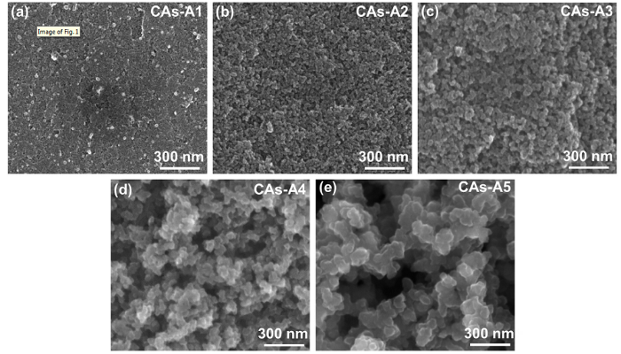
Fig. 1.
SEM images of CAs-A1-A5 with different catalyst concentrations: (a) R/C = 300; (b) R/C = 500; (c) R/C = 1000; (d) R/C = 1500; (e) R/C = 2000.
As displayed in Fig. 2, the measured average particle size and maximum pore diameter increase from 14 ± 7 nm and 35 nm to 183 ± 42 nm and 1193 nm, respectively, when the R/C changes from 300 to 2000. Moreover, it should be worth emphasizing that CAs-A1∼A5 demonstrate a more uniform particles/pores arrangement, finer particle size and more abundant network structure, as compared to the CAs reported by other researchers [14,38,39]. The N2 adsorption-desorption isotherms of CAs-A1∼A5 (Fig. 3(a)) are tested to further explore their pore structures, and the corresponding pore size distributions are displayed in Fig. 3(b). It can be found that when the R/C is 300, CAs-A1 exhibits type I isotherm and a narrow pore size distribution centered at about 2 nm, indicating the dominance of micropores. When the R/C is 500 or 1000, the isotherm of CAs-A2 or CAs-A3 transforms into type IV accompanied by a hysteresis loop which is associated with capillary condensation in mesopores, and their pore size distributions are mainly concentrated in 18 nm and 30 nm, respectively. When the R/C rises to 1500 or 2000, CAs-A4 or CAs-A5 shows a type Ⅱ isotherm and a larger pore size. From these results, it can be concluded that the pore structures of the CAs change gradually from micropores to mesopores and eventually to macropores with the rising R/C, which is consistent with the result of their SEM morphologies. Table 2 displays the porosity parameters of CAs-A1∼A5. The highest BET specific surface area is shown by CAs-A2 (616 m2/g), which can be attributed to its combination of relatively high microporous surface area (350 m2/g) and mesoporous surface area (266 m2/g).
Fig. 2.
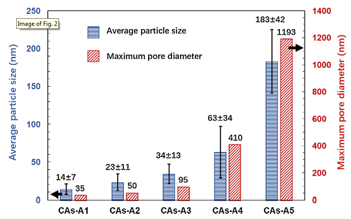
Fig. 2.
Average particle size and maximum pore diameter of CAs-A1∼A5.
Fig. 3.
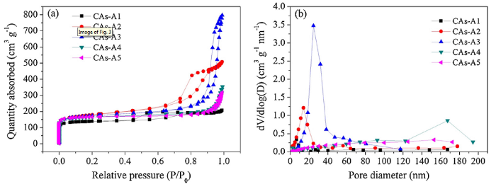
Fig. 3.
Nitrogen adsorption-desorption isotherms (a) and pore size distributions (b) of CAs-A1-A5.
Table 2 Porosity parameters of CAs-A1∼A5.
| Samples | SBET (m2/g) | Smic (m2/g) | Smes (m2/g) | Vpore (cm3/g) | Vmic (cm3/g) |
|---|---|---|---|---|---|
| CAs-A1 | 465 | 382 | 83 | 0.31 | 0.17 |
| CAs-A2 | 616 | 350 | 266 | 0.77 | 0.16 |
| CAs-A3 | 589 | 395 | 194 | 1.14 | 0.18 |
| CAs-A4 | 555 | 436 | 119 | 0.52 | 0.20 |
| CAs-A5 | 558 | 476 | 82 | 0.44 | 0.22 |
Note: SBET: BET specific surface area; Smic: microporous surface area; Smes: mesoporous surface area; Vtot: total pore volume; Vmic: microporous pore volume.
The reaction between resorcinol and formaldehyde involves three processes: activation of resorcinol under catalyst condition, addition of formaldehyde to resorcinol and condensation of hydroxymethyl derivatives. At first, resorcinol molecules would react with hydroxyl to form a sodium resorcinate. Subsequently, hydroxymethyl on the benzene rings is obtained by addition reactions between resorcinate ion and formaldehyde. The resulting resorcinol molecules with hydroxymethyl are highly unstable species, leading to hydroxy methylation with other resorcinol molecules to form a dimer. This process results into CH2 bridge between benzene rings at three possible positions (i.e., ortho, meta and para). The polycondensation process would carry on in the aforementioned manor, ultimately leading to the 3-D interconnected network of organic hydrogels. Therefore, it can be deduced that catalyst triggers the polymerization reaction between resorcinol and formaldehyde, which acts as the nucleation sites of colloidal particles during gelation.
In this work, when the R/C is low (high catalyst concentration), more nucleation sites are available in the sol to generate a large amount of colloidal particles. Then, these colloidal particles tend to aggregate into organic clusters with small dimension and spacing, resulting in the formation of a 3D interconnected network with small particles and pores (Fig. 1(a)). On contrary, when the R/C is high (low catalyst concentration), the nucleation sites are less, and a longer gelation time is required to accomplish the sol-gel reaction. This gives more opportunity for the colloidal particles to aggregate into organic clusters with large dimension and spacing [40]. Hence, a 3D interconnected network with relatively large particles and pores is formed, as shown in Fig. 1(e).
The R/C also has a significant effect on drying shrinkage, as displayed in Table 1. It can be seen that the drying shrinkage declines dramatically from 29.21% to 3.48% with the rise of R/C. This phenomenon can be explained by the variation of particle size and pore diameter caused by the different R/C. When the R/C is high, the microstructure with large particles and pores is more stable against shrinkage during drying in view of the decreased capillary force. However, when the R/C is low, the microstructure with small particles and pores tends to have a more severe shrinkage. It is found that the carbonization shrinkage also decreases from 23.14% to 17.39% with the rising R/C. This may relate to the prompting effect of sodium carbonate on the rearrangement of carbon particles during carbonization [41], which can result in higher carbonization shrinkage for the samples with higher content of sodium carbonate (namely a lower R/C).
Fig. 4 shows the compressive stress-strain curves of CAs-A1-A5. As depicted in these curves, the stress increases linearly to the maximum value and then drops suddenly with limited failure strain (in the range of 4.5-7.5%), corresponding to typically brittle fracture mode. The compressive strength and modulus of CAs are summarized in Table 1. It is found that when the R/C rises from 300 to 2000, the compressive strength and modulus declines significantly from 126.8 MPa to 6.5 MPa and from 1981.3 MPa to 135.4 MPa, respectively. The different mechanical properties should be mainly attributed to their different bulk densities. It should be highlighted that the compressive strengths of CAs-A1∼A5 are significantly higher than that of other reported CA monoliths with similar bulk density [9,11]. For instance, the compressive strength of CAs-A4 (10.8 MPa with a bulk density of 0.37 g/cm3) is about 3 times higher than that of the reported CAs (3.7 MPa with a bulk density of 0.42 g/cm3) [9]. The improved compressive strength can be attributed to the more uniform arrangement of particles and pores, finer particle size and more abundant network structure, as mentioned before. These microstructure characteristics correspond to fewer structure defects and thus can effectively relieve failure caused by stress concentration generated during the fabrication, contributing to the improved strength of CAs.
Fig. 4.
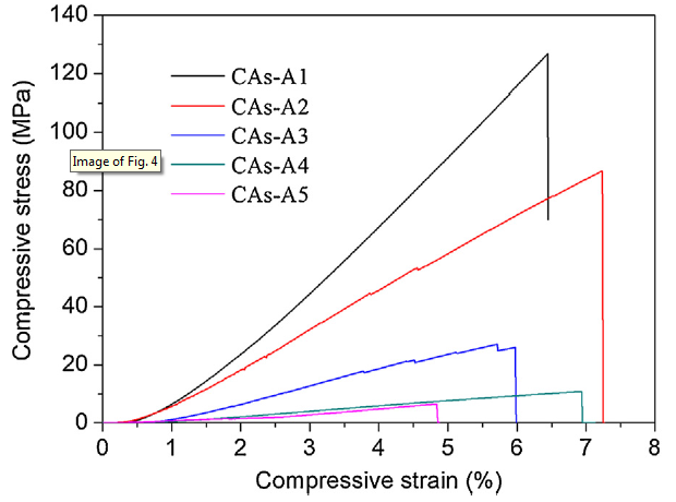
Fig. 4.
Compressive stress-stain curves of CAs-A1-A5.
3.2. Effect of water content (W/R) on microstructures, bulk densities and mechanical properties of CAs
Water content (W/R) is another main affecting factor for synthesis of CAs, since spacing among colloidal particles is largely determined by water content. Accordingly, the samples with a W/R of 24 (labeled as group B) were synthesized in order to investigate the effect of water content on the microstructures and mechanical properties of CAs. It is well-known that reducing reactant concentration is an essential method to decrease bulk densities of RF aerogels. However, we find that the bulk densities of CAs and OAs barely change when the W/R rises from 17 to 24. This is largely related to the higher drying shrinkage of group B as compared to that of group A, as listed in Table 1. The increase in water content can reduce the stacking compactness of organic clusters and eventually weaken the network skeleton of hydrogels. This makes the pore structures tend to shrink more due to the huge capillary force generated during ambient pressure drying. It should be mentioned that CAs-B5 (W/R = 24 and R/C = 2000) appears as sedimentation of flocky clusters rather than monolithic hydrogels, which can be attributed to its high water content and low catalyst concentration. Therefore, the properties of B5 are not listed in Table 1. In addition, the sedimentation of organic clusters becomes more prevalent when the W/R further rises to 32 or 40 (the corresponding samples are not given here).
It is found that the compressive strengths of Group A and Group B are quite different, even though they have similar bulk densities. As compared to those of CAs-A2 (σCA = 84.3 MPa, ρCA = 0.80 g/cm3), the compressive strength of CAs-B2 (σCA = 124.4 MPa, ρCA = 0.82 g/cm3) increases markedly with only a slight increase in bulk density. Moreover, despite the bulk density decreases from 0.54 g/cm3 to 0.51 g/cm3, the compressive strength of CAs-B3 (39.6 MPa) is still higher than that of CAs-A3 (27.1 MPa). Therefore, it can be deduced that the mechanical properties of CAs are not only related to the bulk density but also to the microstructure.
Fig. 5 exhibits the SEM images of CAs-B1∼B4, and the measured average particle size and maximum pore diameter of group B are shown in Fig. 6. It can be found that the average particle size and maximum pore diameter of CAs-B1∼B4 increase from 16 ± 4 nm and 39 nm to 136 ± 23 nm and 986 nm, respectively, which are larger than their counterparts (CAs-A1∼A4). In addition, a small particle size deviation is present in CAs-B1∼B4, which is ±4 nm, ±6 nm, ±7 nm and ±23 nm, respectively. The remarkable structural differences between these two groups can be seen in CAs-B3 and CAs-A3. The network of CAs-B3 is a 3D interconnected chain composed of large particles (∼42 nm) with a small particle size deviation (Fig. 5(c)). Whereas the small particles (∼34 nm) with a large particle size deviation are present in CAs-A3; and its network is characterized by an interconnected chain of relatively large particles attached by some small particles (Fig. 1(c)).
Fig. 5.
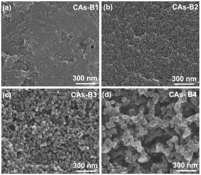
Fig. 5.
SEM images of CAs-B1-B4 with different catalyst concentrations: (a) R/C = 300; (b) R/C = 500; (c) R/C = 1000; (d) R/C = 1500.
Fig. 6.
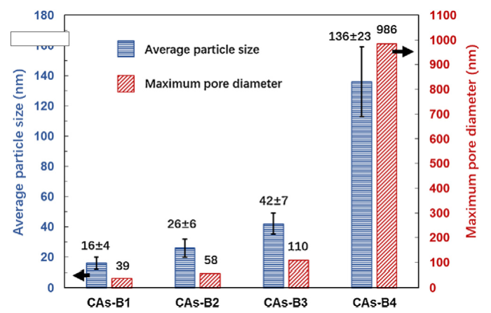
Fig. 6.
The average particle size and maximum pore diameter of CAs-B1-B4.
The increase in particle size and pore diameter for group B is related to the extension of gelation time caused by the low reactant concentration (i.e., high water content). However, the difference of nucleation site spacing should be responsible for the different particle size deviation. When the W/R is controlled at 17, the spacing between colloidal particles is relatively small and a high collision probability exists. Consequently, the organic clusters with different numbers of nucleation sites might be formed during the sol-gel process. The relatively large organic clusters (containing more nucleation sites) tend to aggregate preferentially to form the main chain of network structure, and then the small clusters further grow and attach to its surface. When the W/R is controlled at 24, the organic clusters composed of approximate nucleation site numbers are possibly present since the spacing among colloidal particles is large enough. Thus, the organic clusters with similar dimensions are likely formed, and then aggregate into the main chain of network structure with relatively uniform particle size.
The unique microstructures are responsible for the different mechanical properties of these two groups. For CAs-A1-A3, the relatively low mechanical properties are mainly related to the large particle size deviation since the small particles attached to the main chain has less contribution to the strength of network. However, CAs-B1-B3 exhibit the relatively high compressive strength and modulus because the network with relatively large particle size (large necks) and uniform particle size distribution can bear load more effectively. It should be mentioned that CAs-B4 has a relatively lower mechanical properties (σCA = 8.9 MPa, ECA = 120.3 MPa), as compared to CAs-A4 (σCA = 10.8 MPa, ECA = 156.5 MPa), since the large voids with diameter up to about 1 μm are formed and cause stress concentration (Fig. 5(d)).
3.3. Effect of gelation temperature (Tgel) on microstructures, bulk densities and mechanical properties of CAs
In addition to catalyst concentration and water content, gelation temperature also plays an important role in tailoring microstructure and properties of CAs. A proper gelation temperature is essential to complete polymerization reaction, and thus has a significant impact on the resulting microstructure and mechanical properties of CAs. Based on the results of Sections 3.1 and 3.2, samples with the lowest drying shrinkage can be obtained when R/C = 2000 and W/R = 17. This formulation should be more suitable for the synthesis of low density CAs by ambient pressure drying. Accordingly, samples (labeled as group C) synthesized at different gelation temperatures in the range of 30-90 °C are investigated, in which the R/C and W/R are fixed at 2000 and 17, respectively.
Fig. 7 shows the SEM images of CAs-C1∼C5. A large amount of macropores are present in CAs-C1, while CAs-C2-C5 are characterized by the dominance of mesopores. The measured average particle size and maximum pore diameter of CAs-C1-C5 are displayed in Fig. 8. It reveals that when the gelation temperature rises from 30 °C to 45 °C, the particle size and pore diameter decrease significantly from 183 ± 42 nm and 1193 nm to 65 ± 12 nm and 175 nm, respectively. However, as the gelation temperature continues increasing from 45 °C to 90 °C, the particle size and pore diameter of CAs-C2-C5 have no obvious differences. The average particle sizes of CAs-C2-C5 are measured to be 65 ± 12 nm, 58 ± 10 nm, 53 ± 8 nm, 48 ± 9 nm, respectively, showing a small particle size deviation. The small deviation is also found in group B prepared with a W/R of 24. Therefore, it can be deduced that the particle size uniformity can be improved through the increase in water content as well as the rise of gelation temperature.
Fig. 7.
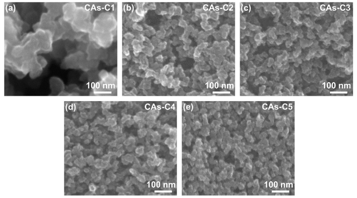
Fig. 7.
SEM images of CAs-C1-C5 with different gelation temperatures: (a) Tgel = 30 °C; (b) Tgel = 45 °C; (c) Tgel = 60 °C; (d) Tgel = 75 °C; (e) Tgel = 90 °C.
Fig. 8.
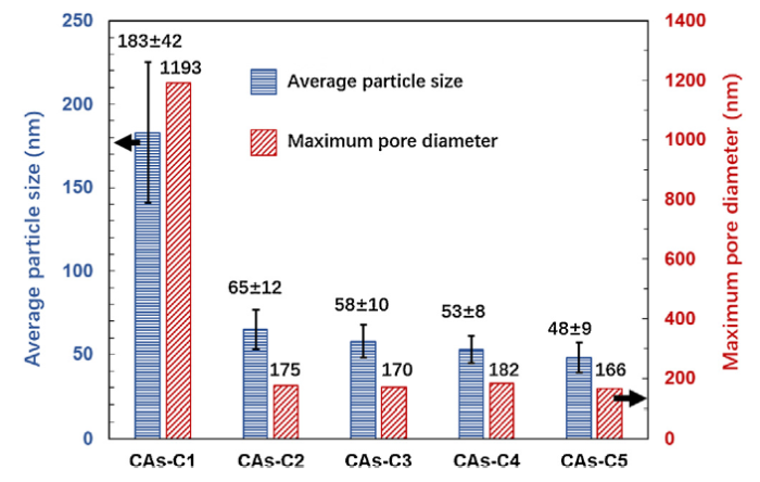
Fig. 8.
The average particle size and maximum pore diameter of CAs-C1-C5.
After preparation of RF solution, gelation temperature should be the most important factor in affecting sol-gel process [42]. We find that the increase of gelation temperature can significantly reduce the gelation time from 3 days (gelated at 30 °C) to 5 min (gelated at 90 °C). The schematic models of the influence of gelation temperature on the network structures of hydrogels are illustrated in Fig. 9. When the sol is gelated at low temperature, the amount of effective nucleation sites is limited since some catalyst can not obtain enough energy to activate the polymerization reaction. It has been found that only a small percentage (≤2%) of effective nucleation sites exist when gelation temperature is low [43]. This should be responsible for the large particle size and pore diameter of CAs-C1 (Fig. 7(a)). The increased gelation temperature can provide enough energy to overcome reaction barrier, resulting in the remarkable increase of effective nucleation sites. Consequently, the spacing among nucleation sites gets smaller with the rise of gelation temperature, which leads to the formation of small particle size and pore diameter in CAs-C2 (Fig. 7(b)). However, due to the limitation of catalyst concentration, the number of nucleation sites could not continue to increase obviously with the further rising of gelation temperature. That should be the reason why a moderate decrease of particle size and pore diameter is shown by CAs-C2-C5 (Fig. 7(b-e)).
Fig. 9.
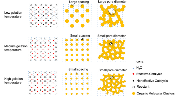
Fig. 9.
Schematic models of the influence of gelation temperature on the network structures of hydrogels.
As listed in Table 1, the drying shrinkage increases from 3.48% to 8.92% when changing the gelation temperature from 30 °C to 45 °C. Subsequently, a relatively mild increase of drying shrinkage from 10.63% to 14.92% is observed with the further rise of gelation temperature from 60 °C to 90 °C. For the bulk density, CAs-C1 and its organic counterpart are the lowest at a gelation temperature of 30 °C, which are 0.30 g/cm3 and 0.31 g/cm3, respectively. With the gelation temperatures rise, the bulk densities increase slightly from 0.40 g/cm3 to 0.47 g/cm3 for the CAs and from 0.42 g/cm3 to 0.46 g/cm3 for the OAs.
Fig. 10 presents the compressive stress-strain curves of CAs-C1∼C5. The lowest compressive strength and modulus of CAs are shown by CAs-C1, which should be attributed to its low bulk density and reduced structural uniformity. Interestingly, it is found that with the rise of gelation temperature from 45 °C to 90 °C, the compressive strength and modulus increase remarkably in spite of the similar bulk density. As illustrated in Table 1, the compressive strength of CAs-C3 (21.4 MPa) is about two times higher than that of CAs-C2 (11.5 MPa); nevertheless, their bulk densities are 0.42 g/cm3 and 0.40 g/cm3, respectively. This should be attributed to their structural differences as discussed below.
Fig. 10.
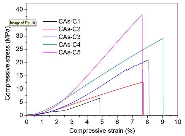
Fig. 10.
Compressive stain-stress curves of CAs-C1-C5.
The structure configurations of CAs can mainly be classified into two types: pearl-necklace, and fibril configuration [32,44]. CAs-C1 gelated at 30 °C shows a typical pearl-necklace configuration, as displayed in Fig. 5(c). However, when the gelation temperature increases to 45 °C, CAs-C2 presents a semi-fibril-like structure due to the improved particle neck (Fig. 7(b)). This phenomenon become more obvious with the further increase of gelation temperature, as revealed in Fig. 7(c-e). It has been confirmed that the CAs with fibril-like structure unusually exhibit the better mechanical properties due to the relatively large contact area between particles [42,45,46]. Therefore, except for the slightly increased bulk densities, the remarkable increase in compressive strength and modulus of CAs-C2-C5 should be mainly attributed to the improved particle neck since they have the approximate particle size and pore diameter. Moreover, the particle neck also has a significant impact on the drying shrinkage. When the neck size increases, the enhanced mechanical strength of the organic network can resist capillary force and prevent pore collapse, which reduces shrinkage during ambient pressure drying [45]. In this work, a very limited drying shrinkage was shown by OAs-C2-C5 (in the range of 8.92%-14.92%) due to the enhanced particle neck.
Undoubtedly, the neck is formed during sol-gel process. In the initial stage of preparation, the solution contains colloidal particles dissolved in a liquid (a sol). As a result of Brownian movement, these particles collide randomly with each other and aggregate together throughout the liquid to form a 3D network (a gel). The gelation temperature can influence the speed of their bouncing and random collisions, which ultimately has an obvious impact on the neck of particles.
As illustrated in Fig. 11, the neck morphologies can be clearly observed by TEM. It can be seen that the particle connectivity and structure uniformity are improved with the rising gelation temperature, and their structure configuration is transformed from a pearl-necklace structure to a semi-fibril-like structure. It has been indicated that when the CAs tolerate an impact or compressive force, only their necks are broken while the carbon particles remain unchanged [46]. Consequently, in order to obtain strong CAs without obvious increase in density, it is crucial to strengthen neck of carbon particles. This can be realized by the gelation temperature increase in an appropriate range as revealed in this work.
Fig. 11.
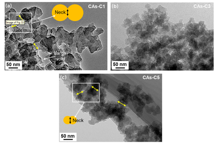
Fig. 11.
TEM images of (a) CAs-C1, (b) CAs-C3 and (b) CAs-C5.
For a comparison, CAs-C3* and CAs-C5* are prepared through ethanol exchange, ambient pressure drying, and carbonization. As displayed in Fig. 12 and Table 1, they exhibit the similar microstructures, bulk densities and mechanical properties as CAs-C3 and CAs-C5, respectively. Therefore, it can be deduced that the solvent exchange is removed successfully due to the improvement of the skeleton network strength. More importantly, the crack-free and large-sized CA monoliths (100 × 100 × 20 mm) with relatively low densities (in the range of 0.31-0.35 g/cm3) are prepared in this work, further demonstrating the high skeleton network strength as well good monolithic forming ability.
Fig. 12.
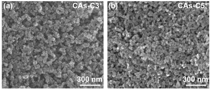
Fig. 12.
SEM images of (a) CAs-C3* and (b) CAs-C5*.
3.4. Thermal insulation properties of CAs
Fig. 13 shows the thermal conductivities of CAs with bulk densities in the range of 0.30-0.82 g/cm3. Overall, thermal conductivities almost increase linearly with the rising of bulk densities. The heat transfer of CAs includes the following three parts: gas conductivity, radiation and solid conductivity [47]. Gas conductivity and radiation are very sensitive to the pore structures of CAs. When tested at room temperature, radiative and gaseous thermal conductivities are usually ignored since they provide slight contribution to the total conductivities [11]. The CAs with higher bulk densities means more solid conducting paths, which usually exhibit higher solid thermal conductivities [47]. Therefore, the thermal properties of CAs are largely determined by their bulk densities. The lowest and highest thermal conductivities are shown by CAs-A5/C1 (0.065 W m-1 K-1) and CAs-B2 (0.120 W m-1 K-1) with densities of 0.30 and 0.82 g/cm3, respectively. In addition, CAs-C2 (0.079 W m-1 K-1), CAs-C3 (0.081 W m-1 K-1) and CAs-C4 (0.086 W m-1 K-1) demonstrate a mild increase in thermal conductivities, which can be attributed to their gradually increased bulk densities and improved particle neck.
Fig. 13.
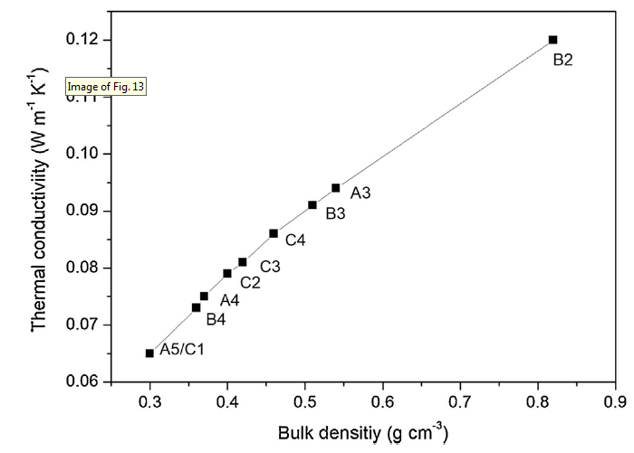
Fig. 13.
Thermal conductivities of CAs with different bulk densities.
4. Conclusions
A simple, fast and cost-effective method for preparing strong CA monoliths was developed through ambient pressure drying without solvent exchange. Synthesis conditions, such as catalyst concentration, water content and gelation temperature played an important role in controlling the microstructures, bulk densities and mechanical properties of CAs. Through tailoring the microstructure of CAs, a series of CA monoliths with high strength of 6.5-147.4 MPa have been prepared since the enhanced skeleton network can effectively resist capillary pressure, and thus can prevent pore shrinkage/collapse and crack during drying. The high strength of CAs could be mainly attributed to the unique microstructures with uniform particles/pores arrangement, fine particle size, abundant network structure and enhanced particle neck. The large-sized CA monoliths (100 × 100 × 20 mm3) have also been prepared by this method, further demonstrating the high skeleton network strength as well good monolithic forming ability.
Acknowledgements
This work has been supported by the Major Program of Aerospace Advanced Manufacturing Technology Research Foundation of NSFC and CASC, China Grant No. U1537204, the National Natural Science Foundation of China Grant No. 51802313 and 51902315, the National Science and Technology Major Project (2017-VI-0020-0093), the Research Fund of Youth Innovation Promotion Association of CAS, China Grant No. 2014171, and the National Key R&D Program of China Grant No. 2018YFF01013600.
Reference
DOI
URL
PMID
[Cited within: 1]

A novel powdery polymer aerogel (PPA) with a hierarchical pore structure was prepared via hypercrosslinking of monodisperse poly(styrene-co-divinylbenzene) nanoparticles. Subsequently, the PPA was carbonized to obtain a powdery carbon aerogel (PCA) with a well-inherited pore structure and a much higher surface area (2354 m(2) g(-1)). The PPA-coated and PCA-coated fibers were easily fabricated benefiting from the powdery morphologies of PPA and PCA, and demonstrated high extraction efficiencies towards hydrophobic analytes owing to their functional groups, unique three-dimensional (3D) porous nanonetworks and high surface areas.
DOI
URL
PMID
[Cited within: 2]
A new high porosity resorcinol-formaldehyde (RF) aerogel with improved particle necking is presented in this work. This RF aerogel was developed under CO2 supercritical drying conditions without any structural shrinkage. The water content and the catalyst percentage were varied to modify the particles' nucleation and growth mechanisms and to control particle-particle connections. The nucleation mechanism solely dependent on the initial catalyst percentage; the number of nuclei increased with the catalyst percentage. However, the growth and connection of the particles dependent on both the water content and the catalyst percentage through their effect on the pH value. As the water content increased to have a larger void fraction, the pH value decreased. Consequently, the spherical growth of the particles became dominant and, thereby, the connection of the particles became more difficult. But as the catalyst percentage increased, the pH value increased, and the connection of the particles became facilitated with the formation of necks around the particles. As a result, the semi-fibril-like structure was developed with a high void fraction. A 30% increase in the structural elasticity and a very low thermal conductivity of 0.0249W/mK were obtained.
DOI
URL
PMID
[Cited within: 1]
This study evaluates a method for rendering syndiotactic polystyrene (sPS) aerogels hydrophilic using polyethylene oxide (PEO) of different molecular weights. The highly porous sPS aerogels are inherently hydrophobic although applications involving absorption of moisture and removal of particulate solids may benefit from the high surface area of sPS aerogels provided some degree of hydrophilicity is induced in these materials. In this work, sPS gels are prepared by thermo-reversible gelation in tetrahydrofuran in the presence of PEO. The gels are dried under supercritical conditions to obtain aerogels. The aerogels are characterized by scanning electron microscopy, nitrogen-adsorption porosimetry, helium pycnometry, and contact angle measurements. The data reveal that the pore structures and surface energy can be controlled by varying the concentration and molecular weight of PEO and using different cooling rates during thermo-reversible gelation. In the first case, sPS aerogels, aerogels containing PEO of a low molecular weight or low concentration show superhydrophobic surface presenting the
An overview on the preparation and properties of resorcinol-formaldehyde (RF) organic and carbon gels reveals the fascinating and remarkably flexible properties of RF carbon and organic gels and how these properties are related to the synthesis and processing conditions. The structural properties can be easily tailored by rigidly controlling such conditions. However, slight variations in some conditions may cause drastic variations in the structural characteristics, and hence properties. Therefore, the effects of different conditions must be well understood before attempting to tailor organic or carbon gels to specific applications. The most important factors that affect the properties of an organic gel are the precursor concentrations, the catalyst type and concentration, the time and temperature of curing, and the drying method. In addition to these factors, characteristics of activated carbon gels also depend on the pyrolysis temperature and the activation method. These conditions impact the structural and performance characteristics significantly.

 WeChat