

1. Introduction
To alleviate the dilemma between energy consumption and environmental deterioration, alternative energy sources, which should be clean, abundant and renewable, are highly desired to substitute for fossil fuels. Among diverse energy techniques (wind energy source, solar battery, lithium ion battery, etc.), water splitting into hydrogen by utilizing the inexhaustible solar energy and earth-abundant water resource is regarded as a promising strategy to address energy crisis. Since Fujishima and Honda who creatively produced hydrogen from a photoelectrochemical cell over Pt-attached TiO2 electrodes in 1972 [1], considerable investigations have been focused on the development of semiconductor-type photocatalysts to promote the process of water splitting [[2], [3], [4]]. However, it still remains a great challenge to obtain highly efficient, chemically stable, low-cost and non-toxic photocatalytic materials. Among various semiconductors exploited for photocatalytic water splitting, the metal-free graphitic carbon nitride (g-C3N4) has garnered extensive attention since Wang and co-workers firstly applied it to photocatalytic hydrogen production [5]. However, several prominent drawbacks of bulk g-C3N4, including low specific surface area, restricted visible-light response and ultra-fast recombination of charge carriers, remains to be settled [[6], [7], [8]]. Besides, as a consequence of high surface over potential for hydrogen release and low separation efficiency of photogenerated charge carriers, pure g-C3N4 showed very low hydrogen evolution activity [[9], [10], [11]]. According to a review summarized by Ran et al. [12], cocatalysts can lower the over potential for H2 or O2 evolution reactions on the surface of semiconductors and are also capable of facilitating the separation of electron-hole pairs at the semiconductor/cocatalyst interface. To date, the most used cocatalysts are noble metals (e.g. Pt, Pd, Au or their alloys) [[13], [14], [15], [16]], which are rare in reserves and expensive in prices. In this context, the high cost of noble metals hampers their potential applications as cocatalysts. Therefore, developing low-cost and highly efficient noble-metal free cocatalysts with high stability is of great significance.
Specifically, many earth-abundant transition metal elements, including cobalt (Co), nickel (Ni), copper (Cu), molybdenum (Mo), and tungsten (W), have been utilized as cocatalysts in their corresponding forms of oxides, sulfides and phosphides [9,11,[17], [18], [19], [20], [21], [22]]. Among them, nickel sulfides stand out due to its low band-gap energy (about 0.9 eV), ease of synthesis and low over-potential for hydrogen release [23,24]. Previous researchers have tried several strategies to fabricate NiS/g-C3N4 composite materials, including direct precipitation method [25], hydrothermal method [10,26], precipitation-hydrothermal method [27], ion-exchange method [28], and photochemical synthesis route [29]. These outstanding works indicated the promising application of nickel sulfides as photocatalytic H2 evolution cocatalysts. However, there still exists much room for NiS-based cocatalysts to improve when compared with noble metal-cocatalysts because the low electrical conductivity of nickel sulfides and the limited contact between the host catalyst and the cocatalyst impede the effective separation of photo-generated charge carriers [30,31]. To address these problems, some efforts have been made. Wen and co-workers [30] constructed metallic Ni interface layers between g-C3N4 nanosheets and amorphous NiS, which are dominantly favorable for separating and transferring photo-excited charge carriers from g-C3N4 to amorphous NiS via metallic Ni. However, a complex three-step process, including the loading of Ni(OH)2 nanosheets, high-temperature H2 reduction to obtain Ni layers, and further deposition of amorphous NiS nanosheets, are needed to fabricate the designed ternary g-C3N4-Ni-NiS composite photocatalyst. On the other hand, sodium hypophosphite (NaH2PO2), a common reducing agent, is usually utilized for electroless Ni plating, which can facilitate the deposition of metallic Ni films onto the surface of various target materials with good adhesion [32]. Also, the deposited Ni films could react with other chemicals to synthesize Ni-containing compounds. For instance, Guan et al. [31] loaded β-NiS onto CdS nanowires via a hydrothermal route, using thiourea and nickel acetate in the presence of NaH2PO2·H2O. According to this report, a metallic Ni intermediate was formed via the electroless plating process assisted by NaH2PO2 and the metallic Ni intermediate subsequently reacted with S2- ions released from thiourea to form NiS. Thus we wonder if NiS can be loaded onto the surface of g-C3N4 nanosheets by electroless Ni plating and corresponding sulfuration, and whether a Ni bridge could be built between g-C3N4 and NiS.
With these aims in mind, in this work, we report a one-pot electroless-assisted hydrothermal method for the synthesis of NiS/g-C3N4 hybrid materials, with a metallic Ni bridge connecting NiS and g-C3N4. This idea is realized by electroless plating of Ni on the surface of g-C3N4 nanosheets, followed by an in-situ sulfuration process in the presence of thiourea under hydrothermal treatment. Without adding any noble metals as cocatalysts, the as-fabricated metallic Ni bridged NiS/g-C3N4 hybrid materials can directly split water to produce H2 under simulated sunlight. This work opens a new avenue for developing highly efficient noble metal-free g-C3N4-based photocatalysts.
2. Experimental
2.1. Raw materials
The applied raw materials, including melamine (C3N3(NH2)3, AR, ≥99%), phosphoric acid (H3PO4, AR, ≥85%), nickel acetate tetrahydrate (Ni(Ac)4·4H2O, AR, ≥98.0%), thiourea (CH4N2S, AR, >99.0%) and triethanolamine ((HOCH2CH2)3N, >78%) were purchased from Sinopharm Chemical Reagent Co., Ltd. (Shanghai, China). Sodium hypophosphite (NaH2PO2, AR) was obtained from Aladdin Ind. Co., Ltd. No further purification was adopted before usage.
2.2. Synthesis
2.2.1. Synthesis of m-CN and b-CN
Mesoporous g-C3N4 (m-CN) was prepared according to our previous report [33]. For the preparation, the concentration of phosphoric acid solution was fixed at 2.5 mol·L-1. Besides, the whole procedure was repeated several times and the obtained pale yellow products were collected together, which was denoted as m-CN. For comparison, bulk g-C3N4 (b-CN) was prepared by directly calcining melamine in a muffle furnace.
2.2.2. Synthesis of NiS/m-CN
The proposed NiS/m-CN hybrid photocatalysts were prepared through an electroless-assisted hydrothermal strategy. After a series of careful trials, the optimized NiS/m-CN hybrid photocatalyst, which possesses the highest photocatalytic H2 evolution activity under the designed conditions, was synthesized as follows. First, about 400 mg of the prepared m-CN material was dispersed in 50 mL of distilled water. At each interval of 10 min, 109.7 mg of Ni(Ac)4·4H2O, 38.8 mg of NaH2PO2 and 167.7 mg of thiourea were in turn added into the suspension with vigorously stirring at 25 °C. After further stirring for 30 min, the suspension was transferred into a 100 mL of Teflon-lined stainless steel autoclave, which was then heated to 160 °C and maintained at that temperature for 12 h. After naturally cooling down to room temperature, the product was filtrated, washed several times by distilled water. Finally, the black gray products was heated in a vacuum oven at 60 °C for 6 h. For the sake of convenience, the sample is labeled as x% NiS/m-CN-y-z, where x, y and z represent the theoretic NiS loading amounts, hydrothermal treatment temperature and duration time, respectively. For instance, the above synthesized optimized catalyst is named as 10% NiS/m-CN-160-12. Other NiS/m-CN hybrid photocatalysts were prepared by changing the hydrothermal treatment conditions or altering the concentrations of the precursors while the molar ratio of Ni(Ac)4·4H2O, NaH2PO2 and thiourea was kept at 1:1:5. The detailed synthesis parameters are presented in Table S1.
2.2.3. Synthesis of pure NiS
Pure NiS material was prepared through a similar hydrothermal method and the adding amounts of precursors were magnified proportionally. Typically, 548.4 mg of Ni(Ac)2·4H2O, 194.0 mg of NaH2PO2 and 838.9 mg of thiourea were utilized. At last, the black powders were collected.
2.2.4. Control experiments
For comparison, several reference samples were prepared. First of all, b-CN was substituted for m-CN to fabricate 10% NiS/b-CN. Besides, NaH2PO2 or thiourea, was removed from the synthesis procedure to prepare directly deposited NiS/m-CN-D or Ni/m-CN. Further, mechanical mixed sample NiS/m-CN-mixed was obtained by grinding certain amounts of m-CN and pure NiS together. Lastly, Ni(Ac)2·4H2O was not added during the preparation to obtain S-doped m-CN material.
2.3. Characterization
Detailed description for the characterization methods is presented in the file of Supporting Information.
2.4. Photocatalytic hydrogen production
In this work, photocatalytic H2 evolution reactions were applied to evaluate the performance of the synthesized catalysts. All the reactions were accomplished in a top irradiation vessel connected to a closed gas circulation system. For a typical test, about 50 mg of the as-fabricated catalyst was dispersed in 100 mL of 10 vol.% triethanolamine aqueous solution, which was contained in a 400 mL vessel. Then the vessel was sealed and evacuated by a mechanical pump to completely remove air inside. Next, the reaction solution was irradiated by a 300 W Xe-lamp (Ceaulight, CEL-HXF300) to stimulate the water splitting reaction. Besides, the temperature was kept steadily at 25 °C by using a water-cooling filter around the vessel. The produced hydrogen was quantified by a gas chromatograph, which was equipped with a thermal conductivity detector (TCD). Argon was used as the carrier gas.
3. Results and discussion
3.1. Synthesis condition
In order to obtain the optimal NiS loaded g-C3N4 material, the reaction parameters, including hydrothermal treatment temperature, duration and NiS loading amounts were systematically investigated.
3.1.1. Hydrothermal temperature
First of all, the hydrothermal temperature was investigated by several controlling experiments. As shown in Fig. 1(a), the H2 evolution performance of NiS/m-CN hybrid materials displays a volcanic pattern with altering the hydrothermal treatment temperature. The sample obtained under 140 °C treatment displays a very low H2 evolution rate and enormous enhancement can be achieved by increasing the treating temperature to 160 °C. It is worth mentioning that the color of the samples compared in Fig. S1 changes from pale yellow to dark grey with temperature increasing from 140 to 180 °C, indicating high temperature can promote the deposition of NiS, which is crucial to lower the surface over potential for hydrogen release. Furthermore, the XRD results also validate this view. As displayed in Fig. 1(b), no obvious diffraction peaks attributed to NiS are discernible from the sample obtained under 140 °C treatment, whereas several peaks belonging to β-NiS (PDF card NO. 86-2281) appear in the samples treated at 160 and 180 °C. At low temperature, thiourea could not be decomposed yet to release S2-, which was essential for the formation of NiS. Besides, the yields of catalysts decreased significantly from 86% to 57% when the treating temperature was increased from 140 to 180 °C. As reported, Ni2+ in the reaction solution may act as a catalyst for the decomposition of g-C3N4 and this process could be accelerated by higher reaction temperature [10]. In addition, the extra emerged diffraction peak at 10.8° for samples treated at 160 and 180 °C may be ascribed to the in-planar pattern of C-N networks containing triazine rings formed as a result of the partial decomposition of g-C3N4 [10,34], further providing evidence for this point. On the basis of the above results, 160 °C was adopted as the optimized reaction temperature.
Fig. 1.

Fig. 1.
(a) The effects of hydrothermal treatment temperature during loading NiS (10 wt.%) with duration fixed at 6 h on the H2 evolution performance and the yields of catalysts; (b) XRD patterns of the samples obtained under different hydrothermal temperature. (Sample yield refers to the percentage of NiS/m-CN product obtained versus the theoretical amounts).
3.1.2. Hydrothermal duration time
Apart from the hydrothermal temperature, the duration of the treatment is another important factor affecting the properties of the catalysts. In this case, the duration for the hydrothermal treatment under the optimized temperature was also carefully studied. As shown in Fig. 2(a), when the duration was increased from 6 to 18 h, the sample yields slightly decreased from 82% to 63%, which could also be resulted from the partial decomposition of g-C3N4 materials under long time hydrothermal treatment. Obviously different from the variation trend of sample yields, the H2 evolution rate reached its highest value when 12 h of hydrothermal treatment was implemented. Besides, the XRD patterns displayed in Fig. 2(b) reveal that the intensity of β-NiS-related diffraction peaks slightly enhanced with prolonged hydrothermal duration, signifying increased crystalline degree or bigger particle size of NiS nanoparticles. Combining the highest H2 evolution rate (1419 μmol g-1 h-1) with the acceptable sample yield (69%), 12 h of treatment was taken as the optimized duration for the synthesis of NiS/m-CN hybrid photocatalysts.
Fig. 2.

Fig. 2.
(a) The effects of hydrothermal treatment duration during loading NiS (10 wt.%) with temperature fixed at 160 °C on the H2 evolution performance and the yields of catalysts; (b) XRD patterns of the samples obtained under different hydrothermal duration.
3.1.3. NiS loading quantity
The loading quantity of cocatalyst NiS is also crucial to the performance of the hybrid photocatalysts. By modulating the adding amounts of NiS precursors (Table S1), a series of NiS/m-CN hybrid photocatalysts were synthesized. As presented in Fig. 3, both bare m-CN and pure NiS displayed a very low H2 evolution rate, which could be attributed to the ultrafast recombination between the photo-generated electrons and holes [30]. Besides, the S-doped m-CN displayed no better H2 evolution rate than bare m-CN, indicating sulfur doping has little effect on the photocatalytic performance of g-C3N4 without cocatalyst. Notably, the H2 evolution performance can be remarkably improved by loading a small amount of NiS onto g-C3N4. As exhibited, the H2 evolution rate reached a maximum value of 1419 μmol g-1 h-1 with 10 wt.% theoretical NiS loading amount, which was 34 and 14 times higher than the bare m-CN and NiS, respectively. This result indicates that NiS could act as excellent cocatalyst to accelerate the water splitting process in g-C3N4. However, further increasing NiS loading quantity to 12.5 wt.% resulted in a decrease in H2-evolution rate, which was mainly due to the unexpected light scattering and block effects of an overdose of NiS on g-C3N4 surface [30,35].
Fig. 3.

Fig. 3.
The H2 evolution rates of NiS/m-CN with different NiS loading amounts and the comparison of several control experiments.
In addition, several reference samples were prepared and their H2 production activity was also evaluated. The H2 evolution activity of the mechanical mixed sample (10% NiS/m-CN-mix) was also tested, which was only one quarter of the optimal one. It is expected that NiS loaded via an in-situ electroless-assisted hydrothermal treatment owns a better interface and contact with the g-C3N4 nanosheets than the mechanical mixed one. Good adhesion could promote the electron transfer between the heterojunctions, thus leading to improved H2 evolution performance. Besides, by substituting b-CN for m-CN, an obvious decrease in H2 evolution rate was observed, indicating the characteristic properties of the substrate material could also play a decisive role on the performance of the NiS/g-C3N4 hybrids. In comparison, m-CN possesses 3.1 times larger BET surface area than b-CN (Fig. S2). Larger specific area can not only provide more active sites, but also promote the uniform distribution of NiS nanoparticles on the surface of the substrate, both of which are prone to improve the photocatalytic performance of the catalysts [27,36]. Furthermore, in order to verify the necessity of NaH2PO2, direct deposited sample was also prepared only without adding NaH2PO2. Interestingly, the H2 evolution rate of 10% NiS/m-CN-D sample was only 218 μmol g-1 h-1, much lower than the value when NaH2PO2 was utilized. Surprisingly, the color of the catalyst (shown in Fig. S3) obtained without adding NaH2PO2 is obviously lighter than that of the optimized sample, which demonstrates less amount of NiS has been successfully deposited onto g-C3N4 under the designed synthesis condition. It was reported that H2PO2- can accelerate the decomposition of thiourea to release S2-, thus facilitating the formation of NiS [31]. It is also proven that NiS acted as the main cocatalyst for water splitting, as little H2 could be produced when the sample was synthesized without sulfur precursor. These results verified the indispensable role of NaH2PO2 in promoting the deposition of NiS on g-C3N4 and the functional mechanism of NaH2PO2 was discussed intensively later in this work.
3.2. Morphology, composition and formation mechanism
To obtain an overview of the synthesized materials, TEM characterization was applied. As shown in Fig. 4(a), the m-CN material exhibits typical silk-like structure and the transparent features imply the formation of thin g-C3N4 nanosheets. From Fig. 4(b), we could find that pure NiS is composed of aggregated flake-like nanosheets, with a size around 1~2 μm. The flake-like structure could be distinguished more clearly from the SEM image in Fig. S4. Furthermore, the microstructure of 10% NiS/m-CN-160-12 was also revealed by TEM and HRTEM. As presented in Fig. 4(c), the silk-like structure of g-C3N4 is well retained and numerous dark nanoparticles with the diameter of 50 ~ 110 nm are uniformly scattered on the surface of g-C3N4. The obviously decreased particle size and homogeneous distribution of NiS particles indicate that the mesoporous g-C3N4 nanosheets served as a good substrate for attaching NiS nanoparticles with high dispersion, in congruency with the XRD results (Fig. S5). To reveal the formation of intimate contact between g-C3N4 nanosheets and NiS nanoparticles, higher magnification was focused on the edges of one particle (labeled by red circle in Fig. 4(c)). As shown in Fig. 4(d), intimate interface could be observed between g-C3N4 and NiS, which is crucial for efficient charge transfer between the two semiconductors. Besides, four portions (marked as A, B, C and D in Fig. 4(d)) were carefully magnified to identify the crystal structure. Area A and B all display a lattice plane with a spacing of 0.203 nm, matching well with the typical (111) plane of metallic Ni, roughly confirmed the formation of metallic Ni [30,37]. Area C and D exhibit lattice fringes of 0.252 and 0.241 nm, which could be attributed to the (021) and (220) plane of β-NiS, respectively (PDF card NO. 86-2281). It is expected that the metallic Ni species between the interface of g-C3N4 and NiS could act as a bridge for charge transfer from g-C3N4 to NiS, thus improving the hydrogen evolution performance [30]. Besides, a structure with poor crystallinity is found near the interface of NiS (Fig. S6), and its attribution will be discussed later in this work.
Fig. 4.

Fig. 4.
FE-TEM images of m-CN (a), NiS (b) and 10% NiS/m-CN-160-12 (c-h).
To gather more information about the distribution of NiS and g-C3N4 in the hybrid material, a selected area in the TEM image of sample 10% NiS/m-CN-160-12 (Fig. 5(a)) was applied for dark-field TEM characterization with elemental mapping analysis. As shown in Fig. 5(b,c), elements C and N almost display similar distribution density, which implies the existence of g-C3N4 structure. As for Ni and S elements, homogenous dispersed bright spots could be observed from Fig. 5(d,e), further verifying that the observed nanoparticles in the TEM images were NiS particles. Notably, the density for Ni element is obviously higher than S element in the whole view region. The atomic% of Ni and S in this region are determined to be 0.35% and 0.19% by EDS, demonstrating the existence of other Ni species except for NiS.
Fig. 5.
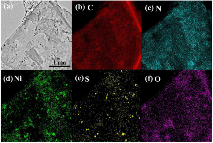
Fig. 5.
Elemental mapping images of the selected area in the TEM image of 10% NiS/m-CN-160-12.
Then, detailed XPS characterization was carried out to determine the chemical composition of nickel species on the as-synthesized samples and to identify the chemical states of the component elements. The XPS survey spectra exhibited in Fig. S7(a) indicated the presence of elements S, C, N, O and Ni in the hybrid sample 10% NiS/m-CN-160-12. The corresponding high resolution XPS spectra of C 1s, N 1s, S 2p and Ni 2p are shown in Fig. S7(b)-(e), respectively. The C 1s spectrum of m-CN in Fig. S7(b) can be deconvoluted into three peaks centering at 284.6, 286.5 and 287.4 eV, corresponding to the signal of C-C bonds of graphitic impurities, the sp2-hybridized carbon atoms attached to the -NH2 group (C-NH2) or bonded to nitrogen atom inside the triazine rings (N-C = N), respectively [33,38]. There is an extra peak located at 288.7 eV in the C 1s spectrum of 10% NiS/m-CN-160-12, which is attributed to the O-C=O [39]. In Fig. S7(c), four peaks could be fitted for the N 1s spectrum of m-CN. The peaks centering at the binding energies of 398.4, 399.6, 400.7 and 404.1 eV could be assigned to the sp2-hybridized nitrogen bonded to carbon atoms in the form of C-N=C, the tertiary nitrogen N-(C)3 in tri-s-triazine, the uncondensed C-N-H and charging effects in g-C3N4 structures, respectively [33]. No distinct variations could be found for the high-resolution C 1s and N 1s spectra of 10% NiS/m-CN-160-12 and m-CN, reaffirming the basic framework of g-C3N4 was well retained after electroless-assisted hydrothermal treatment. In the high-resolution XPS spectrum of S 2p (Fig. S7(d)), three pairs of peaks could be fitted for pure NiS. The peaks located at 162.6 and 161.5 eV are close to the binding energies of S 2p1/2 and S 2p3/2 in NiS, respectively [31]. The other two peaks centered at 164.4 and 163.3 eV are assigned to S 2p1/2 and S 2p3/2 orbitals of divalent sulfide ions (S2-), respectively [40]. The last two peaks at 169.7 and 168.6 eV may be attributed to S in a higher valence state (+6), originating from the hydrolysis of thiourea during the hydrothermal treatment [31]. Whereas for the composite sample 10% NiS/m-CN-160-12, the signal for S 2p spectrum is obviously weaker than the pure one, demonstrating little NiS species existed on the surface. Two weak peaks are fitted at the binding energies of 163.4 and 162.2 eV, which can be assigned to S 2p1/2 and S 2p3/2 in NiS. For the Ni 2p3/2 spectra of pure NiS (Fig. S7(e)), the peak at 853.0 eV is close to the reported value for NiS, and the other two peaks at 856.1 and 861.2 eV can be assigned to the main and satellite peaks of Ni2+ cations in Ni(OH)2, which was derived from the hydrolysis of Ni(CH3COO)2 under hydrothermal conditions [31,41]. To our surprise, no NiS-related peaks could be deconvoluted from the Ni 2p3/2 spectrum of the composite sample and only Ni(OH)2 is observed. This result indicates that the surface of the composite sample may be fully wrapped by Ni(OH)2, as XPS can only detect the surface composition of solid material within ~ 10 nm [42]. However, Ni(OH)2 species was not detected by the preceding XRD characterization, which might be due to the fact that Ni(OH)2 exists in an amorphous structure and it is of poor crystallinity [31]. In this case, the structure with poor crystallinity observed near the interface of NiS by the previous HRTEM characterization in Fig. S6 should be amorphous Ni(OH)2.
In order to reveal the NiS species, we tried to peel the Ni(OH)2 layers over the NiS nanoparticles by argon cluster ions (Arn+, n = 1000) etching, which was considered as a very useful tool to get the in-depth information without destroying the surface structure of unstable catalytic material [43,44]. After sputtering with an Arn+ beam, XPS signals originating from C, N, Ni, and S elements are observed at all etching depths (Fig. 6). No obvious changes could be found for the C 1s and N 1s spectra, which are obviously different from the results of monoatomic Ar+ etching (traditional Ar+ source, applied in most XPS equipment, results presented in Fig. S8), signifying little damage was introduced to the basic framework of g-C3N4 after the relative “gentler” Arn+ etching. After sputtering, a new peak emerged at ca. 853.1 eV in the Ni 2p3/2 signals, which preliminarily confirmed the existence of NiS species. Whereas for the reference sample prepared without adding NaH2PO2 (10% NiS/m-CN-D), no such peak attributing to NiS can be fitted from its Ni 2p spectra even after Arn+ etching (Fig. S9). What’s more, the relative atomic concentration (%) of sulfur atoms before and after etching were 0.06% and 0.03%, further indicating the vital effect of NaH2PO2 in controlling the formation of NiS under the designed experimental conditions.
Fig. 6.

Fig. 6.
Comparison of high-resolution C1s (a), N 1s (b), Ni 2p3/2 (c) and S 2p spectra (d) of sample 10% NiS/m-CN-160-12 with different etching time.
By fitting the Ni 2p3/2 and S 2p peaks, we estimated the relative atomic concentration (%) of Ni and S elements and their corresponding ratio in the form of NiS with different sputtering time, which are summarized in Table 1. Surprisingly, the element ratio of Ni:S in the form of NiS does not match the expected value of 1:1 for NiS. Instead, the Ni species ascribed to NiS form tend to be enriched in the inner layers. It is worth mentioning that the binding energies for Ni species in the form of NiS or metallic Ni are all around 853.0 eV [31,45], which increases the difficulties in distinguishing these two Ni species when they are coexistent. Combining the HRTEM results that observed lattice fringes for metallic Ni between the interface of NiS and g-C3N4, the excess Ni species corresponding to sulfides could be determined to be metallic Ni.
Table 1 The relative atomic concentration (%) of Ni and S elements in the form of NiS with different sputtering time and their corresponding ratio.
| Etching time /s | 0 | 60 | 120 | 180 | 240 | 300 | 360 | |
|---|---|---|---|---|---|---|---|---|
| Ni 2p | B.E/eV | -- | 853.1 | 853.2 | 853.1 | 853.0 | 853.0 | 853.0 |
| Atom content/% (A) | 0 | 0.10 | 0.14 | 0.19 | 0.32 | 0.27 | 0.31 | |
| S 2p | B.E/eV | 162.2 | 162.2 | 162.1 | 162.2 | 162.0 | 162.0 | 162.1 |
| Atom content/% (B) | 0.09 | 0.14 | 0.15 | 0.19 | 0.16 | 0.19 | 0.21 | |
| A/B | 0 | 0.71 | 0.93 | 1.00 | 2.00 | 1.42 | 1.48 |
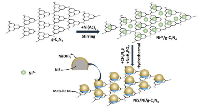
Based on the aforementioned discussions, a feasible formation mechanism for the metallic Ni bridged NiS/m-CN hybrids is proposed in Scheme 1. Under magnetic stirring, the hydrolyzed Ni2+ ions could be adsorbed onto g-C3N4 by coordinating with its tri-s-triazine ring structure [28,46]. At the early stage of the subsequent hydrothermal process when thiourea is not decomposed yet at low temperature, a quantity of the homogeneous adsorbed Ni2+ ions are reduced into metallic Ni via electroless plating with the assistance of H2PO2-, which could be illustrated as follows [31]:
Scheme 1.
Scheme 1.
Proposed formation mechanism for metallic Ni bridged NiS/g-C3N4 hybrids.
As the temperature rises, the electroless plating process is gradually ceased as a result of high temperature, meanwhile thiourea is decomposed to release S2- into the suspension. Instantly, the highly reactive metallic Ni would react with S2- to form NiS crystal seeds:
With the reaction continuously proceeded, the surface-exposed metallic Ni is completely transformed into NiS and the crystal seeds grow up into nanoparticles gradually with the reaction of Ni2+ and S2-:
As a result, NiS nanoparticles are successfully loaded onto the surface of g-C3N4 nanosheets, with metallic Ni layers connecting these two semiconductors. Besides, amorphous Ni(OH)2 species derived from the hydrolysis of Ni(Ac)2 under hydrothermal conditions are homogeneously distributed and the surface of the NiS nanoparticles are also covered by amorphous Ni(OH)2 layers.
3.3. Optical properties, band structures and charge-separation performance
Optical absorption properties are vital characters controlling the photocatalytic performance of semiconductor-based catalysts. In this case, UV-vis diffuse reflectance spectroscopy (DRS) were applied to evaluate the optical character of the synthesized NiS/m-CN hybrid materials. As shown in Fig. 7(a), m-CN displays intense absorption from UV to visible light range, with absorption edge (λg) located at 461 nm, corresponding to the intrinsic absorption of g-C3N4 from valence to conduction band [35]. Whereas for pristine NiS, the almost complete absorption over the whole region is mainly due to its dark color and narrow band gap [47]. After introducing NiS cocatalyst, the NiS/m-CN samples show obviously enhanced light absorption over the whole range, in well accord with their color changes from light yellow to black gray (Fig. S10). The significantly improved light harvesting of NiS/m-CN hybrids are foreseeable to enhance their photocatalytic performance, as corroborated in Fig. 3. Besides, as shown in Fig. S11, the absorption edges of the composite catalysts are slightly blue-shifted compared to that of m-CN. Furthermore, the band gap energies (Eg) are estimated by utilizing the equation of Eg = 1240/λg, where Eg and λg refer to the band gap energy and the absorption edge of semiconductor, respectively [33]. As displayed in Table 2, the Eg of m-CN, 5%, 7.5%, 10% and 12.5% NiS/m-CN hybrids are 2.69, 2.75, 2.79, 2.74 and 2.71 eV, respectively. The bandgap of m-CN is only slightly influenced by loading NiS, which would have little influence on its electronic properties. In order to further investigate the effect of NiS loading on the electronic structure of g-C3N4, XPS valence band spectra were conducted and shown in Fig. 7(b). The valance band maximum (VBM) for bulk g-C3N4 (m-CN) and 10% NiS/m-CN-160-12 (NiS/Ni/g-C3N4) are determined to be 1.96 and 1.66 V (vs. NHE at pH 7.0), by utilizing the reported formula ENHE/V = Φ + Ef - 4.44 (ENHE: potential of normal hydrogen electrode; Φ =4.50 eV: the electron work function of the analyzer; Ef: the Fermi level, obtained by XPS valence band spectra) [48]. Combined with the band gap energies obtained by UV-vis DRS (Table 2), an absolute energy scheme for VB and CB positions of g-C3N4 and NiS/g-C3N4 are depicted in Fig. 7(c). The CB potential of NiS/Ni/g-C3N4 is more negative than that of g-C3N4, indicating the photo-excited electrons on the CB of the composite sample possess stronger reduction ability for water reduction.
Fig. 7.

Fig. 7.
(a) UV-vis DRS and (d) PL spectra of NiS/m-CN (A: m-CN, B: 5% NiS/m-CN, C: 7.5% NiS/m-CN, D: 10% NiS/m-CN, E: 12.5% NiS/m-CN, F: NiS, G: 10% NiS/m-CN-D); (b) XPS valence band spectra and (c) Schematic illustration of the band positions for m-CN (g-C3N4) and 10% NiS/m-CN-160-12 (NiS/Ni/g-C3N4).
Table 2 Absorption edges and band gap energies of NiS/m-CN samples with different NiS loading quantity.
| Samples | Absorption edge (nm) | Band gap energy (eV) |
|---|---|---|
| m-CN | 461 | 2.69 |
| 5% NiS/m-CN | 451 | 2.75 |
| 7.5% NiS/m-CN | 444 | 2.79 |
| 10% NiS/m-CN | 453 | 2.74 |
| 12.5% NiS/m-CN | 457 | 2.71 |
To understand the key roles of cocatalyst in accelerating the transfer and separation of photo-induced charge carriers, photoluminescence (PL) spectra were employed since PL originates from the recombination of free electron-hole pairs [47]. Generally, the higher the PL intensity, the faster the recombination of charge carriers. The PL spectra of NiS/m-CN hybrids with different NiS contents are presented in Fig. 7(d). Under an excitation wavelength of 370 nm, a strong emission peak located at around 450 nm could be observed for m-CN, corresponding to the direct band gap electron-hole recombination of g-C3N4 [28]. As expected, the PL intensity dropped significantly upon loading NiS and the optimized sample 10% NiS/m-CN-160-12 showed the lowest charge carrier recombination rate. Besides, the PL intensity of 10% NiS/m-CN-160-12 was also obviously lower than that of the directly deposited one (10% NiS/m-CN-D), which is mostly owing to its more efficient transfer of charge carriers from g-C3N4 to NiS through the metallic Ni bridge, thus efficiently reducing the recombination rate of electrons and holes [30].
3.4. Mechanism and stability
Based on the discussions above, a possible underlying photocatalytic H2-production mechanism in the metallic Ni bridged NiS/g-C3N4 composite systems is proposed in Scheme 2. Under simulated sunlight irradiation, the VB electrons of g-C3N4 are excited to its CB, leaving holes in its VB. For NiS, the energy level of its CB is lower than that of g-C3N4, allowing the electrons transfer from g-C3N4 to NiS via the metallic Ni bridge [30]. The reduction of H2O to H2 involves two steps: in step (1), H+ ions dissociated from H2O molecules receive an electron trapped by NiS to form the intermediate HNiS. In step (2), HNiS reacts with another H+ and electron to release a H2 molecule and NiS is recovered [28,49]. Simultaneously, sacrificial agent TEOA will be oxidized to TEOA+ by the reactive holes on the VB of g-C3N4, thus impeding the recombination of electrons and holes.
Scheme 2.

Scheme 2.
Proposed mechanism for photocatalytic H2 evolution reaction on the as-prepared metallic Ni bridged NiS/g-C3N4 hybrid catalyst.
When evaluating the performance of photocatalysts, stability and reusability are also vital factors. First of all, four consecutive experiments were carried out on the optimized material 10% NiS/m-CN-160-12 under the same condition. After each cycle, the produced H2 inside the reactor was evacuated thoroughly before the next test. The results in Fig. 8(a) revealed that the optimized photocatalyst maintained excellent H2 evolution stability during the cycling tests. After four cycles, the amount of produced H2 was about 87% of the first cycle, still much higher than other NiS/m-CN hybrid materials in this system. Besides, the catalyst after cycling test was collected and submitted to XRD, TEM and XPS characterizations to verify its structure stability. As shown in Fig. S12 and S13, the similar XRD diffraction patterns and morphologies of the catalyst before and after photocatalytic reactions demonstrated its excellent stability to light irradiation. However, the surface chemical composition of the fresh and used catalyst is slightly different. As shown in Fig. S14, NiS-related peaks could be directly fitted from the spectra. The exposure of NiS may be due to the process of vigorous stirring during the photocatalytic H2 evolution reaction, which physically peeled away some of the outer amorphous Ni(OH)2 layers. Besides, no new Ni species were produced, which proved the stability of NiS cocatalyst to some extent. Moreover, after six month storage, the aged catalyst was tested and it displayed a H2 evolution rate of 1165 μmol g-1·h-1, which was 82% of the fresh one, also implied the structure stability of this hybrid material. Combining the unique structure of this hybrids proposed in Scheme 1, the superior stability is probably due to the following causes: (i) the surface of NiS species are almost wrapped by amorphous Ni(OH)2 layers, which limited the direct contact of NiS with light irradiation to some extent, thus alleviating its photo-corrosion effect; (ii) besides, the Ni(OH)2 layers could also protect the NiS species from atmospheric air, slowing down the oxidation rate of NiS.
Fig. 8.

Fig. 8.
(a) Recycling tests on 10% NiS/m-CN-160-12 and (b) comparison of H2 evolution performance for the fresh and aged photocatalyst.
4. Conclusion
In summary, metallic Ni bridged NiS/ mesoporous carbon nitride hybrids have been successfully prepared through a one-pot electroless-assisted hydrothermal method which involves four steps in sequence: (1) adsorption of Ni2+ ions onto mesoporous carbon nitride nanosheets by coordinating with its tri-s-triazine ring structure; (2) reduction of the adsorbed Ni2+ ions into metallic Ni via electroless plating with the assistance of NaH2PO2; (3) reaction of the highly reactive metallic Ni with S2- to form NiS crystal seeds; (4) growth of the crystal seeds with the reaction of Ni2+ and S2-. The metallic Ni species serve as a charge-transfer bridge, which could facilitate the transfer and separation of photo-induced electrons and holes between mesoporous carbon nitride and NiS, thus enormously enhancing the water splitting reaction. Notably, the surface of the loaded NiS nanoparticles are fully wrapped by amorphous Ni(OH)2 layers, which could alleviate photo-corrosion effect of NiS species and protect them from oxidation by atmospheric air. By elaborately adjusting the loading quantity of NiS, the optimized 10% NiS/m-CN-160-12 catalyst show the highest H2 evolution rate of 1419 μmol g-1 h-1, which is about 34 and 14 fold higher than that of bare mesoporous carbon nitride and NiS, respectively. Benefitted from the unique Ni(OH)2 wrapping structure, the as-prepared hybrid catalysts exhibited superior stability under light irradiation and also maintained excellent H2 evolution performance after storage for six months. This work put forward a promising strategy to design highly efficient and stable noble metal-free photocatalysts and shed light on the role of metal bridge in accelerating the transfer and separation of charge carriers.
Appendix A. Supplementary data
Supplementary material related to this article can be found, in the online version, at doi:https://doi.org/10.1016/j.jmst.2019.11.020.
Acknowledgements
The authors gratefully acknowledge the financial support of the project from the National Natural Science Foundation of Shanghai (19ZR1403500), NNSFC (Project 21373054) and the Natural Science Foundation of Shanghai Science and Technology Committee (19DZ2270100).
Reference

The production of H-2 by photocatalytic water splitting has attracted a lot attention as a clean and renewable solar H-2 generation system. Despite tremendous efforts, the present great challenge in materials science is to develop highly active photocatalysts for splitting of water at low cost. Here we report a new composite material consisting of TiO2 nanocrystals grown in the presence of a layered MoS2/graphene hybrid as a high-performance photocatalyst for H-2 evolution. This composite material was prepared by a two-step simple hydrothermal process using sodium molybdate, thiourea, and graphene oxide as precursors of the MoS2/graphene hybrid and tetrabutylorthotitanate as the titanium precursor. Even without a noble-metal cocatalyst, the TiO2/MoS2/graphene composite reaches a high H-2 production rate of 165.3 mu mol h(-1) when the content of the MoS2/graphene cocatalyst is 0.5 wt 96 and the content of graphene in this cocatalyst is 5.0 wt 96, and the apparent quantum efficiency reaches 9.796 at 365 nm. This unusual photocatalytic activity arises from the positive synergetic effect between the MoS2 and graphene components in this hybrid cocatalyst, which serve as an electron collector and a source of active adsorption sites, respectively. This study presents an inexpensive photocatalyst for energy conversion to achieve highly efficient H-2 evolution without noble metals.

 WeChat