Search for articles:
Miao Cao , Qi Zhang
Corresponding authors:
Received: 2019-04-26
Revised: 2019-09-1
Accepted: 2019-09-13
Online: 2020-04-01
Copyright: 2020 Editorial board of Journal of Materials Science & Technology Copyright reserved, Editorial board of Journal of Materials Science & Technology
More
Abstract
A complete rheo-forming process was carried out to investigate the rheoforging process of C3771 lead brass valve, starting from the semi-solid billet preparation to rheoforging experiments and material performance tests. The near-spherical micro-grains with mean equivalent diameter of 56.3 μm, shape factor of 0.78 were obtained when the raw C3771 lead brass were rotary swaged to a radial strain of 0.22 and then heated to 895 °C for 5 min. The Forge 3D software was used to analyze the temperature, strain and strain rate distribution of copper valve for obtain the reasonable process parameters during the subsequent rheoforging process. The experiment results showed that near-spherical micro-grains were stretched and refined to about 35.7-43.4 μm in different positions due to the dynamic recrystallization during the rheoforging process. The cap thread and nut thread failure torque of the so-produced valve are also discovered to be higher than the traditionally forged copper valve with dendrite micro-grains, with an enhancement of the cap and thread failure torque of 42.2 % and 28 %, respectively.
Keywords:
Compared with casting and forging, semisolid metal processing (SSP) [1] may be a potential method to fabricate high melting point metals, such as copper and its alloys. Subliquidus temperature of rheocasting and less load of thixoforging decrease the thermal and pressure shocks on the forming die, thereby increasing its service life and save cost [2,3]. For low melting point alloys (e.g. aluminum alloy and magnesium alloy), the thixoforming parts have been used in automobile and communication products [4,5]. However, the thixoforming of high melting point alloys over 800 °C has not been achieved on an industrial level due to the preparation difficulties related to the high temperature [6].
For high melting point alloys, electromagnetic stirring and mechanical stirring are not suitable for semi-solid slurry preparation due to the difficulties in temperature control and measurement of temperature resistance of the tool materials. Strain-induced melt activation (SIMA) method [7] for copper alloys is one of the suitable SSM methods. A modified SIMA method has been proposed, which includes the following two steps subsequent to casting: severe plastic deformation (SPD) [8] and reheating the deformed material to the mushy zone temperature. SPD, e.g., equal angular channel pressing [8,9], high pressure torsion [10], multidirectional forging [11], was utilized to smash the initial dendritic casting structure and to introduce sufficient stored energy to be introduced. Globular microstructures were formed during the final heating step. Major barriers of these SIMA methods to the industrial applications are the low efficiency and limitation of large-size materials. In order to enhance productivity of SSM materials, rotary swaging (RS) was introduced to SIMA method for deforming copper bars or pipes. Cao et al. [12] named this SIMA method as rotary swaging strain-induced melt activation (RSSIMA) method. Lim et al. [13] and Gan et al. [14] described that RS is one of the SPD methods for reducing the cross-sections of rod and tube materials. It is usually a cold or hot working process, and its main application is the progressive deformation of rods and tubes, as well as the concentric reduction. Abdulstaar et al. [15] used RS to produce other regular forms, e.g., hexagonal, octagonal, and square sections. As reported by Laplanche et al. [16], RS can improve the deformation uniformity of the forming pieces due to the three direction stress resulting from the high-frequency pulsed stroking. The rotary swaged workpieces are then heated to semi-solid state by isothermal heat treatment (IHT) to obtain near-spherical grains. Therefore, RSSIMA method differs from traditional SIMA processes in that it has high productivity with $6 \tilde{8}$ m/min for bars or pipes and it is able to prepare large-size materials.
Thixoforming, one of the SSM forming routes, involves semi-solid billet preparation, reheating and forming process [17]. In order to save energy and improve production efficiency, thixoforming for SIMA was simplified by removing the reheating step in this study. We called the modified thixoforming as rheoforming. The whole rheoforming process of semi-solid lead brass valve was studied. The deformation characteristics on semi-solid lead brass were investigated using finite element analysis by FORGE 3D [18] software and experiment. The mechanical properties of rheoforged copper valves and conventional forged valves were investigated by thread failure torque tests and hardness tests.
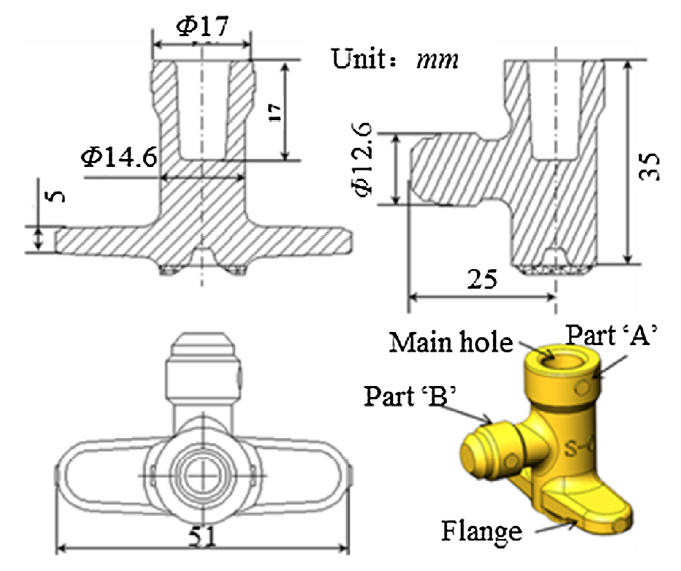
The valve as the research object, valve height is 35 mm, the main hole depth is 17 mm, and the total length of flange is 51 mm, as shown in Fig. 1. For the conventionally forged valve preparation, 120 tons hydraulic extruder was used to forge the valve. The as-cast billet temperature was 740 °C and the mold temperature was 350 °C. In this study, the valve was produced by rheoforging process.
Fig. 1. Two-dimensional drawing of valve.
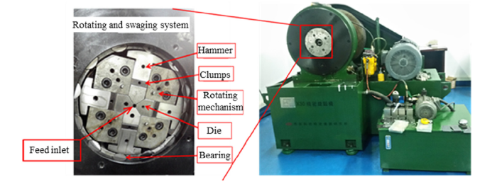
Firstly, feedstock with diameter of 18 mm and length of 1500 mm was rotary swaged to a diameter of 14 mm at the room temperature. A rotary swaging machine is presented in Fig. 2. There are usually 4 dies arranged concentric around the workpiece, and these dies move progressively in the radial direction. At the same time, the feedstock move forward, and then the feedstock rotate by 15°. The feedstocks were rotary swaged step by step and the radial deformation of each step was 1-2 mm. Then the rotary swaged feedstocks were cut into small cylinders. Then the small cylinders were processed by IHT at a predetermined temperature in the solidification range and holding time of 5-10 min, after that the cylinders were quickly placed in cold water to obtain the semi-solid billet microstructures.
Fig. 2. RS machine produced by Xi’an Innovation Precision Instrument Research Institute.
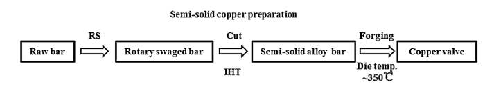
The production process flow of semi-finished valve is shown in Fig. 3, the whole process includes semi-solid copper preparation and forging. After IHT, the rotary swaged samples immediately removed from the furnace into the hydraulic extruder mold for forging. Semi-solid copper valve were obtained from previous step with near-spherical grains microstructure.
Fig. 3. Rheoforging process flow of copper valve.
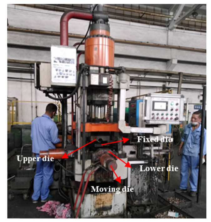
35 t hydraulic extruder was used to rheoforging of the valve, as shown in Fig. 4. The semi-solid billet temperature was 890 °C, 895 °C and 900 °C, the isothermal heating time was 5 min and 10 min, mold temperature was about 350 °C. During the forging process, the semi-solid billet was put into the die, the upper die and the lower die closed quickly, and then the moving die moved at forging speed of 30 mm/s, and it stopped until the main hole depth reached to 17 mm. Finally, the semi-finished product was removed from the forming die, and was cooled by air according to industrial practice.
Fig. 4. 35 tons hydraulic extruder.
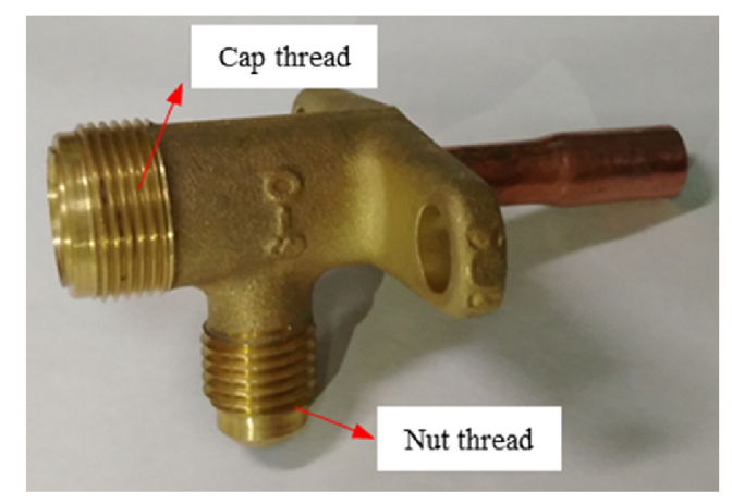
When the valve is installed on the pressure pipe, the fluid pressure, fluid flow impact, installation error and other factors make the valve withstand torque and moment. That may shorten the service life of the valve. Thus, it is necessary to test the thread breaking torque to determine a safe working area. The cap thread and nut thread are showed in Fig. 5. Refrigeration industry requires cap thread failure torque ≥ 40 N m, nut thread breaking torque ≥ 30 N m. Torque test device was thus used to test the failure thread torque of the cap and nut in the valve assembly state. Firstly, the valves were fixed on the test device, mounting the cap or nut on the thread. Then the torque was gradually increased until the thread broken by torque wrench. This torque is the thread failure torque of valve.
Fig. 5. Cap thread and nut thread.
3.1.1. Solidus and liquidus
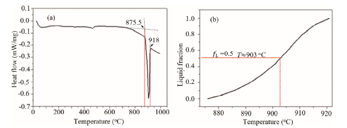
The C3771 lead brass samples were composed of 59.3 % Cu, 1.8 % Pb, 38 % Zn and other elements in insignificant amounts. Differential scanning calorimetry (DSC) of heating curve was analyzed for the rotary swaged C3771 alloy in the solidification range. The solidus and liquidus of the rotary swaged C3771 were found to be 875.5 °C and 918 °C, respectively, according to the tangent method (Fig. 6(a)). The liquid fraction fL could be obtained using integrated and normalized, as shown in Fig. 6(b). At the same temperature, semi-solid materials had the same liquid fraction. It is well known that liquid fraction of 0.1-0.5 (885-903 °C) is suitable for semi-solid forging.
Fig. 6. Liquid fraction of rotary swaged C3771 alloy: (a) DSC vs. temperature curve; (b) liquid fraction vs. temperature curve.
3.1.2. Rheological behavior of semi-solid copper
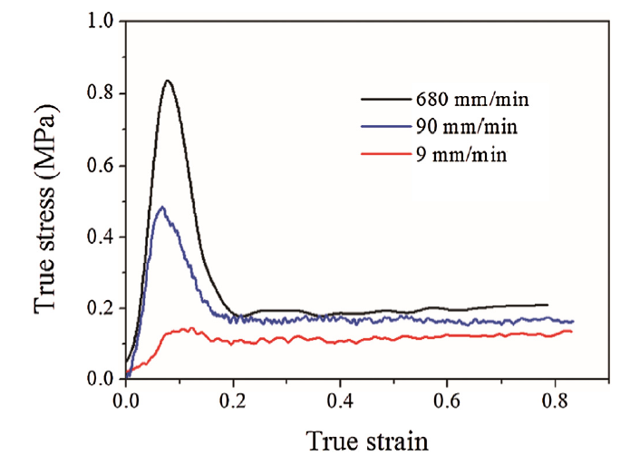
Unit-axial compression tests of RSSIMA-processed C3771 were carried out using a 100 kN Instron tester in the semi-solid state to provide the semi-solid material deformation behavior. The upper ram movement and the data collection were controlled by the materials testing system of Instron tester. Once the furnace heated to the preset temperature, the samples with diameter 10 mm and height 15 mm were put into the furnace and held for about 5 min to ensure that the sample temperature reached homogeneously to the predetermined temperature. Argon was applied to shield the copper alloys from being oxidized during the heating process. Then the upper ram moved down and compressed the semi-solid C3771 copper. The total compress strain was 0.8. The high temperature deformation behavior of C3771 at different initial strain rates from the thermo-mechanical tests is presented in Fig. 7. It can be seen from the Fig. 6 that the curves exhibited a peak flow stress at nearly strain of 0.1, and then the peak stress gradually decrease until it reaches a relatively steady state when the strain exceeds 0.3. The flow stress behaviour suggests that discontinuous dynamic recrystallization (DDRX) has taken place for these samples. This is quite likely considering the high deformation temperature and the low stacking fault energy of copper alloys [19].
Fig. 7. True stress-strain curves of RSSIMA-processed C3771 at 900 °C.
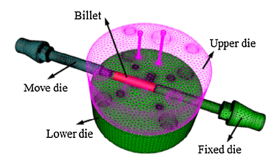
The rheoforging process finite element models were established using the FORGE 3D software. The geometric model of the forging die was presented in Fig. 8. During the rheoforging process, the upper and lower dies were assembled tightly together with the fixed die, and the moving die compress the billet until the main hole depth of 17 mm. The billet material was semi-solid C3771 copper alloy, and stress-strain curves (see Fig. 7) of semi-solid C3771 at high temperature can be imported into FORGE 3D software directly. All models were simulated with the same process parameters: the C3771 copper alloy billets with a dimension of Ø14 mm × 60 mm were extrude at rheoforging speed of 20 mm/s and 30 mm/s, and rheoforging temperature of 890 °C, 895 °C and 900 °C, and friction coefficient of viscoplasticity of 0.3. The billet was divided into 19,166 tetrahedral solid elements and the different forming dies were meshed as rigid parts by the triangular shell elements, which included the lower die together with the fixed die (shown in green in Fig. 8), upper die, and move die with 23,573, 19,696 and 12,137 grids, respectively.
Fig. 8. Geometry of the rheoforging die.
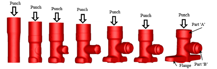
Fig. 9 shows the semi-solid metal flow at rheoforging temperature at 900 °C, the rheoforging speed of 30 mm/s and the die temperature of 300 °C. The moving die pushed the metal to contact with the fixed die firstly and the part ‘A’ was filled. Then metal flow to the part ‘B’ cavity, and the flange cavity was filled finally. The simulation results of copper valve in the last step were shown in Fig. 10. The temperature decreased from the part ‘B’ to the flange and further to the part ‘A’. The equivalent strain in part ‘A’ and the flange was lower than the strain in part ‘B’ and the equivalent strain in most locations exceeded 0.72. For the strain rate, the highest strain rate concentrated on the part surface, part ‘A’ and the flange. These results suggested that temperature, equivalent strain and strain rate distribution in the valve was not uniform during the rheoforging process.
Fig. 9. Metal flow in rheoforging process.
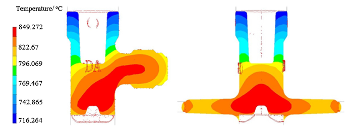
Fig. 10. Simulation results in the last simulation step at rheoforging temperature at 900 °C with the rheoforging speed of 30 mm/s and the die temperature of 300 °C: (a) temperature distribution of copper valve; (b) equivalent strain distribution of copper valve; (c) strain rate distribution of copper valve.
The rheoforging speed affects the deformation resistance and plastic deformation ability of semi-solid materials. Fig. 11 shows the temperature field distribution when the billet temperature is 900 °C, the die temperature is 300 °C, the viscoplastic model friction coefficient is 0.3, and the forging speed is 20 mm/s. Compared to the temperature field at 30 mm/s (see Fig. 10), it can be seen that the forging speed has a great influence on the temperature field of the material. When the forging speed is 30 mm/s, the maximum temperature of billet after filling the die cavity is higher than the forging speed of 20 mm/s about 30 °C.
Fig. 11. Temperature distribution of copper valve in the last simulation step at rheoforging temperature at 900 °C, the speed of 20 mm/s and the die temperature of 300 °C.
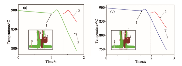
In order to accurately study the change of the temperature field during the rheology forging process, tracking points were selected at each of the Part 'A', flange and Part 'B' positions. Fig. 12 shows the temperature variation of the tracking point with the rheoforging time. It can be seen that in the initial stage of rheoforging, the temperature of the semi-solid material increases due to the deformation energy conversion to heat energy during the deformation process, and then the heat exchange with the die and semi-solid materials causes the temperature to drop. The temperature of the material at position 1 and position 2 is between 880 °C and 903 °C. The material temperature at position 3 of 30 mm/s and 20 mm/s are about 840 °C and 819 °C, respectively. To ensure the uniform of the deformation microstructure and the low forming resistance, the rheoforging deformation temperature should be at the semi-solid temperature range as far as possible, and the temperature distribution of copper valve should be uniform as much as possible.
Fig. 12. Temperature change with rheoforging timee of the tracking pionts: (a) 30 mm/s; (b) 20 mm/s.
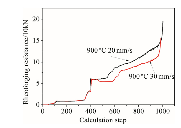
The rheoforging speed variation affects the forming resistance during the copper valves rheoforging. As shown in Fig. 13, the rheoforging resistance increases as the calculation step increases. When the forging speed of 30 mm/s is the maximum forging force of 154 kN and the forging speed of 20 mm/s, the maximum forging force is 194 kN. The forming resistance during the rheoforging of the copper alloy semi-solid billet decreases as the forging speed increases. The deformation law is in contrast to that of the copper alloy semi-solid material which obtained by isothermal compression test in the semi-solid temperature range. This is because the influence of temperature on the forming resistance of copper alloy semi-solid materials is relatively larger than the rheoforging speed. The rheoforging process is a temperature-changing process in which the billet temperature is gradually decreased with rheoforging speed.When the forging speed is slow, the forging time of the billet forging will increase, and the temperature drop will be larger, which will lead to the rheoforging force increased. Therefore, the reasonable rheoforging speed is 30 mm/s during the rheoforging of the complex valve.
Fig. 13. Forging force variation with the calculation step during the rheoforging process.
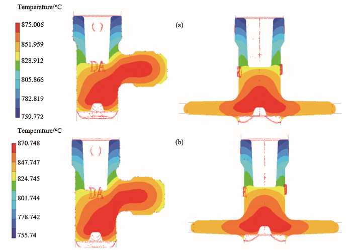
The rheoforging temperature is a key factor in metal flow ability. When the forging speed is 30 mm/s, the die temperature is 300 °C, and the viscoplastic model friction coefficient is 0.3, the temperature field distributions at different initial forging temperatures of semi-solid billet are shown in Fig. 14. The final rheoforging temperature increases with the increase of the initial rheoforging temperature, and the final temperature of Part 'A' is lowest. There has been a strong heat exchange between the moving die punch and semi-solid materials due to the moving die punch at room temperature. The temperature of the moving die punch is gradually increased after multiple rheoforging, which will improve the Part 'A'. Therefore, the temperature field distribution of the formed part will uniform, and the final microstructure of formed part become even.
Fig. 14. Temperature field distributions at different rheoforging temperatures of semi-solid billet: (a) 895 °C; (b) 890 °C.
The liquid phase has more excellent flow behavior than the solid phase, thus the liquid phase flow to the part surface preferentially. That will results liquid phase segregation and orange peel defect. These defects will increased with the temperature increasing due to the increase of liquid phase volume fraction. Therefore, the temperature of the semi-solid material should not be too high. However, increasing the initial forging temperature can reduce the forming resistance of complex valve parts. Considering, the reasonable initial temperature range of the semi-solid billet is 890-895 °C during the rheoforging of the complex valve.
The as-cast C3771 microstructures exhibit heterogeneous grain structures, as shown in Fig. 15(a), which consists of dendrites, long striped grains and spherical grains. The rotary swaged microstructure of C3771 is presented in Fig. 15(b). Dendritic grains and long striped grains were broken down and the density of the micro-grains increased in the unit area, but the dendrite trunks still existed. That is because the C3771 lead brass is subjected to severe cold rotary swaging for metal to be flowed along with cylindrical spiral lines. During the last step where the rotary swaged alloys are heated to 890-900 °C and held for 5 or 10 min. The microstructures exhibit near-spherical structures, as shown in Fig. 11. Mean equivalent diameter of solid particles $D=\sqrt{4A/π}$ and shape factor F=4πA/P2 were used to describe the spheroidal grains [17], where the mean perimeter length P of spheroidal particles and the surface area A can be obtained through Image-Pro Plus software from the sectioned surface.
Fig. 15. Microstructures of C3771 copper alloy: (a) as-cast; (b) rotary swaged.
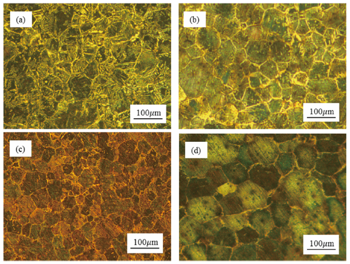
The IHT of rotary swaged C3771 lead brass samples were carried out at the temperatures of 890 °C, 895 °C and 900 °C holding for 5 min, and then the near-spherical micro-grains obtained, as shown in Fig. 16(a)-(c). The average equivalent diameter D of the near-spherical micro-grains were 63.8 μm, 56.3 μm and 44.7 μm, and the shape factor FS were 0.54, 0.62, and 0.64, respectively. The results showed that the average equivalent diameter D and shape factor FS decreased as the heat treatment temperature increasing. When the holding time increased from 5 min to 10 min at 900 °C, and the average equivalent diameter D increased from 44.7 μm to 99.4 μm (see Fig. 16(c) and (d)). It illustrated The average equivalent diameter D coarsened with the increase of the holding time. Considering the accuracy of the tube furnace, grain size and energy consumption, the reasonable process parameters are 895 °C for 5 min.
Fig. 16. Rotary swaged C3771 microstructures at different IHT conditions: (a) 890 °C holding for 5 min; (b) 895 °C holding for 5 min; (c) 900 °C holding for 5 min; (d) 900 °C holding for 10 min.
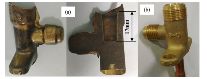
The semi-finished rheoforged valve and finished rheoforged valve were presented in Fig.17(a) and (b), respectively. It can be seen that the semi-finished semi-solid forged valve had fewer burrs, and both the flange and letters in valve body were fully filled.
Fig. 17. (a) Semi-finished rheoforged valve and (b) finished rheoforged valve.
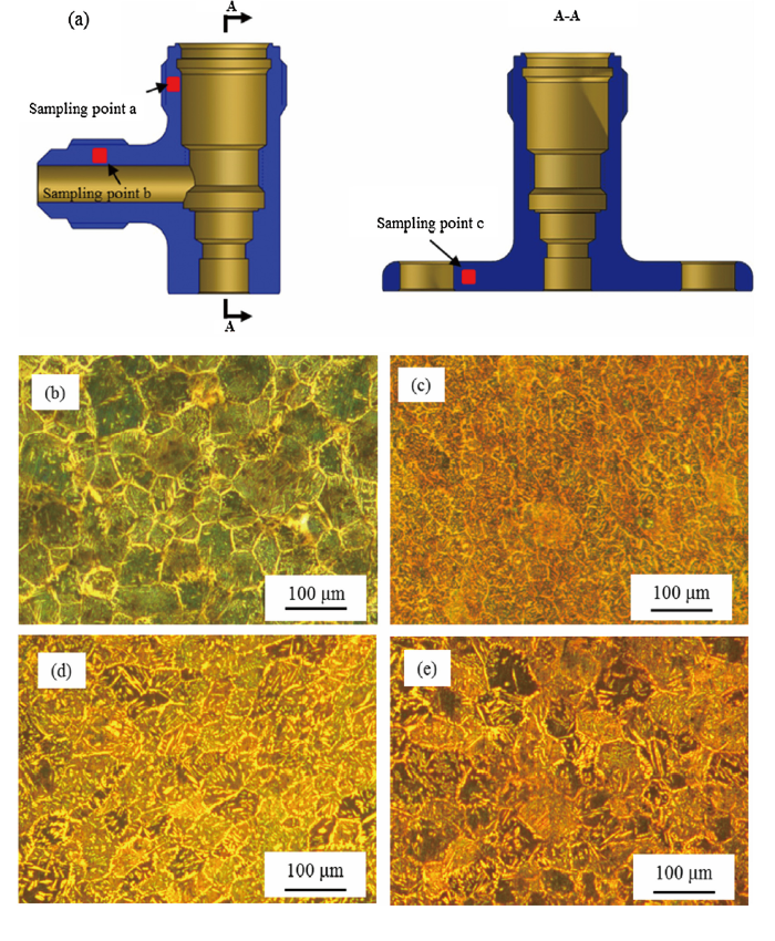
In order to understand the effect of forging pressure on the microstructural evolution of rheoforged valves, their microstructures in different positions of valves were observed, as shown in Fig. 18. Compared with the initial semi-solid billet microstructure, the solid near-spherical micro-grains and liquid phase in the microstructures now distributed inhomogeneously, and the size and shape (in terms of shape factor) of near-spherical micro-grains decreased. Microstructure still consisted of small near-spherical micro-grains after forging, but the micro-grains shape and dimension in different positions (see Fig. 18(a)) were heterogeneous. In the ‘a’ position, the density of near-spherical micro-grains increased, and the near-spherical micro-grains were deformed. The shape factor FS was 0.60 and mean equivalent diameter D was about 35.7 μm. In the ‘b’ position, the density of the near-spherical micro-grains increased, and the near-spherical micro-grains were also deformed. The shape factor FS was 0.58 and mean equivalent diameter D was about 43.4 μm. In the ‘c’ position, the near-spherical micro-grains were elongated, while the micro-grains were larger than ‘a’ and ‘b’ position. The shape factor FS was 0.68 and mean equivalent diameter D was about 42.1 μm.
Fig. 18. (a) Sampling position in rheoforging valve, (b) microstructure of IHT copper alloy with a radial strain value of 0.3 at 895 °C holding for 6 min and microstructures in rheoforging valve for (c) sampling position a, (d) sampling position b and (e) sampling position c.
In order to further understand the semi-solid copper deformation mechanism, the metal flow rule during rheoforging process was studied. The semi-solid copper was forged by moving die, the liquid phase was flowed firstly due to its lower yield strength. The liquid flows to positions with lower pressure. Continuing to compress the solid micro-grains forces them to contact with each other. This means the microstructure is rearranged during rheoforging. The deformation behavior is consistent with the jump-up in shear rate theory in Ref. [20]. The semi-solid slurry undergoes an initial rapid breakdown, associated with the breakdown of the solid particles. Ludwig et al. [21] provided the experimental evidence of the existence of a solid skeleton, which was obtained through tomography of semi-solid alloy structures.
According to Rollett theory [22], dynamic recrystallization (DRX) occurs during the semi-solid forging deformation, where the original grains can be refined. In fact, DRX is the only way to refine the grain size during thermo-mechanical processing after casting for materials without phase transformation. DRX describes the process where nuclei of new dislocation-free grains appear and grow during the deformation step. As soon as the material is fully recrystallized, the mean diameter of micro-grains is only a function of the strain rate and deformation temperature [19]. The different equivalent strain at different positions (all over 0.3) clearly indicates that the material is fully recrystallized from Fig. 7, Fig. 10(b). The grain sizes at ‘a’, ‘b’ and ‘c’ after semi solid forging were smaller than that after IHT, indicating that DRX has taken place at these positions. The fact that the grain sizes at positions ‘b’ and ‘c’ are quite close is in line with their similar temperature and strain rate after rheoforging. However, it is also possible that post dynamic recrystallization (PDRX) has also occurred during the air cooling after semi solid forging. The grain size after rheoforging at position ‘a’ is smaller than the grain size at positions ‘b’ and ‘c’. This is because the temperature of part close to position ‘a’ was lower than 800 °C (see Fig. 10(a)) together with a very high strain rate (see Fig. 10(b)), it is not surprising that the dynamically recrystallized grain size is the smallest. Moreover, part ‘A’ cooled faster due to larger cooling area during air cooling after the deformation which could significantly delay the PDRX. This means the microstructure close to position ‘a’ only experienced dynamic recrystallization during rheoforging.
In summary, the different grain structures observed at different positions is related to the different deformation mechanism of semi-solid C3771 alloy during the rheoforging process.
Cap thread and nut thread failure torque is an important indicator to determine the quality of copper valve. Usually, it is required that the cap thread damage torque must be higher than 40 N m, nut thread breaking torque must be higher than 30 N m. The thread failure torques of semi-solid valve were shown in Table 1, the results showed that thread failure torque of semi-solid valve all met the customer requirements with a pass rate of 100 %. The main cap thread damage torque was 57.6 N m and the average nut thread breaking torque was 54.8 N m. The thread failure torques of conventionally forged valve were shown in Table 2, the results showed that thread failure torque pass rate was 60 %. In this case, the main cap thread damage torque was 40.5 N m and the average nut thread breaking torque was 42.8 N m. Compared with the conventional forging valve, the semi-solid valves have excellent performance, with an enhancement of quality and stability of 42.2 % and 28 %, respectively.
Table 1 Cap thread and nut thread failure torque of semi-solid copper valve.
| Number | 1 | 2 | 3 | 4 | 5 |
|---|---|---|---|---|---|
| Cap thread damage torque (N m) | 50 | 52 | 62 | 65 | 59 |
| Nut thread breaking torque (N m) | 55 | 56 | 53 | 55 | 55 |
Table 2 Cap thread and nut thread failure torque of traditionally forged copper valve.
| Number | 1 | 2 | 3 | 4 | 5 |
|---|---|---|---|---|---|
| Cap thread damage torque (N m) | 37.5 | 35 | 44 | 40 | 46 |
| Nut thread breaking torque (N m) | 47 | 45 | 43 | 42 | 37 |
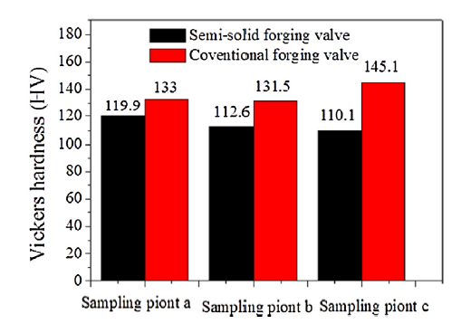
The Vickers hardness of the sampling point of Fig. 18(a) in semi-solid forged valve and conventionally forged valve were tested, as shown in Fig. 19. It demonstrated that the conventionally forged valve has higher Vickers hardness than that of semi-solid forged valve. Even though further details on the microstructure of the traditionally forged valve were not presented, PDRX or static recovery during air cooling after removing the valve from the forming die must have significantly reduced the dislocation density in the semi-solid forged valve due to the higher operating temperature. The decrease in dislocation density can lead to a decrease in strength, which can be roughly estimated by hardness value. This reduction was advantageous to reduce residual stresses of forged valve and to improve the toughness of the tested material.
Fig. 19. Vickers hardness of semi-solid forged valve and conventional forged valve.
The whole process of rheoforging process of RSSIMA-processed C3771 copper alloy was investigated. The main conclusions could be obtained as follows:
(1) The semi-solid C3771 lead brass were prepared by RSSIMA method, which near-spherical micro-grains with mean equivalent diameter of 56.3 μm, shape factor of 0.78 at 895 °C holding for 5 min.
(2) The reasonable parameter of rheoforging process of complex valves is obtained by simulation: the semi-solid billet temperature of 890-895 °C and rheoforging speed of 30 mm/s. The valve was forged at 895 °C and 30 mm/s according the rheoforming process flow chart. The rheoforged C3771 lead brass valve deformation behavior analysis by simulation was in accordance with the experiment results. The micro-grains size of valve microstructures refined after rheoforging (about 35.7-43.4 μm) was due to the dynamic recrystallization, also the micro-grains shapes were stretched during the forging process.
(3) The cap thread and nut thread failure torque of semi-solid copper valve was obtained by torque failure tests. The cap thread and nut thread failure torque of semi-solid copper valve, which was forged at 895 °C and die speed of 30 mm/s, was higher than that of conventional forging copper valve, with improvement of quality of 42.2 % and 28 %, respectively. The Vickers hardness had the opposite trend. The results showed that the toughness of rheoforged copper valves is better than the conventional forging copper valves.
This work was supported financially by the Fundamental Research Funds for Central University, the National Natural Science Foundation of China (Nos. 51875441 and 51805415), by the Shaanxi province Natural Science Basic Research Program (Nos. 2019JQ-598 and 2019JM-125), and by State Key Laboratory of Materials Processing and Die & Mould Technology, Huazhong University of Science and Technology.

 WeChat
/
| 〈 |
|
〉 |

