Search for articles:
H. Zhang, P. Xue , D. Wang, L.H. Wu, D.R. Ni, B.L. Xiao, Z.Y. Ma
Corresponding authors:
Received: 2018-11-18
Revised: 2018-12-28
Accepted: 2018-12-30
Online: 2019-07-20
Copyright: 2019 Editorial board of Journal of Materials Science & Technology Copyright reserved, Editorial board of Journal of Materials Science & Technology
More
Abstract
In this study, different welding parameters were selected to investigate the effects of heat-input on the microstructure and corrosion resistance of the friction stir welded high nitrogen stainless steel joints. The results showed that, the welding speed had major influence on the duration at elevated temperature rather than the peak temperature. The hardness distribution and tensile properties of the nugget zones (NZs) for various joints were very similar while the pitting corrosion behavior of various NZs showed major differences. Large heat-input resulted in the ferrite bands being the pitting location, while tool wear bands were sensitive to pitting corrosion in the low heat-input joints. Cr diffusion and tool wear were the main reasons for pitting. The mechanisms of pitting corrosion in the NZs were analyzed in detail.
Keywords:
High nitrogen stainless steels (HNSs) have been utilized in many industrial fields as a promising advanced structural material [1]. The high nitrogen content of HNSs led to excellent localized corrosion resistance and mechanical properties, but it deteriorated the weldability of HNSs [2].
Different kinds of defects were detected in the fusion welded joints of HNSs, such as blowhole, weld cracking and nitrogen loss [[2], [3], [4]]. The composition of the shielding gas used during fusion welding should be well controlled to obtain pore-free HNS joints [5], resulting in increased process complexity and cost. Moreover, ultra-high nitrogen content HNSs led to high tendency of desorption during the fusion welding process which would make the fusion welding even harder. Therefore, HNSs that can be welded by the fusion welding techniques generally had a nitrogen content of lower than 0.6% [4,6,7].
It was reported that the corrosion resistance of the fusion welded HNS joints would be deteriorated because of the high heat-input [8,9]. Ogawa et al. [8] studied the pitting corrosion resistance of gas tungsten arc welded HNS joint in detail. It was shown that the segregation of chromium and molybdenum caused by solidification in the weld metal deteriorated the pitting corrosion resistance. Precipitation of chromium nitride was also confirmed in the heat affected zones (HAZs) of the HNS joints [9]. Critical pitting corrosion temperature (CPT) showed a great relevance with nitride precipitation and the CPT dropped against holding time above 1073 K. Fusion welding was also not suitable for the welding of HNS thin sheets due to the severe post weld distortion. Therefore, for the welding of HNS thin sheets with ultra-high nitrogen content, low heat-input joining methods are required.
As a solid-state joining method, friction stir welding (FSW) has attracted more and more attention due to its energy efficiency, low distortion, absence of cracking [[10], [11], [12], [13], [14]] and is therefore considered as a promising method for the welding of HNSs. Park et al. [15] first introduced FSW into the welding of HNSs. Miyano et al. [16] reported that defect-free joints achieved by optimizing the welding parameters showed higher strength and hardness than the base material (BM). Wang et al. [17] further investigated the microstructure and mechanical properties of the FSW HNS joints and found that no sigma phase and nitrogen loss were detected in the nugget zone (NZ).
From these previous studies, it is clear that FSW showed great advantages in the welding of HNSs. Because no melting occurred during FSW, the phenomenon of nitrogen loss in fusion welding process could be avoided. Moreover, the mechanical properties of the NZs were significantly improved compared to those of the BM due to the grain refinement [[16], [17], [18]]. It is important to point out that, as a kind of high-performance stainless steel, HNSs were expected to have many utilizations in aggressive environments. Therefore, the mechanical properties of the FSW joints should not be the only criteria to evaluate the welding quality, the corrosion resistance should be taken into account in the assessment.
From the detailed microstructure studies, the formation of ferrite and the wear of the welding tools were observed in the FSW HNS joints [16,17,19], however, further analyses about the effects of ferrite phase transformation and tool wear on the corrosion behavior have not been made. In the fusion welded HNS joints, ferrite phase was confirmed to have harmful effects on the pitting corrosion and interphase corrosion properties due to the formation of Cr-depleted zones [20,21]. It could be deduced that the corrosion behaviors of the FSW HNS joints could also be influenced by ferrite. On the other hand, the introduction of tool wear debris could also have harmful effects on corrosion resistance due to corrosion potential differences.
Heat input of FSW can be adjusted by altering welding parameters [22]. Because of the poor thermal conductivity and high strength of HNSs, the FSW parameters for HNSs were generally limited to a narrow range. The studies about the influences of heat input on the microstructure and properties of the FSW HNS joints are very limited and mainly focused on the mechanical properties; no relations between heat-input and corrosion resistance of the FSW HNS joints have been explored. It should be noted that different heat-inputs could result in microstructural changes of ferrite and tool wear, then led to different corrosion behaviors. Thus, more attention should be paid on the phase transformation and tool wear to further understand the corrosion behaviors of the FSW HNS joints.
In this study, the microstructural changes of the FSW HNS joints with different heat inputs were studied in detail, aiming at achieving high quality HNS joints with excellent comprehensive properties and further clarifying the mechanism of pitting corrosion of the joints.
1.8 mm thick solid solution-treated HNS sheets were selected as the BM and the chemical composition is listed in Table 1. To obtain joints with different heat inputs, different welding speeds of 25, 50 and 150 mm/min were selected at a constant rotation rate of 500 rpm. For simplicity, the welding parameters were abbreviated as 500-25, 500-50 and 500-150. W-Re alloy welding tool with an 11 mm in diameter shoulder and a 5.7 mm diameter cylindrical pin 1.67 mm in length was used for FSW. An argon gas shield was employed during welding to prevent the oxidation of the joints.
The Vickers microhardness measurements of the cross sections of the welded joints were taken at the middle thickness of the joints with a load of 500 g and a dwell time of 15 s. Tensile tests of the NZs and the BM were conducted at room temperature with a constant strain rate of 1 × 10⁻³ s-1. The tensile specimens had a gauge length of 2.5 mm, a gauge width of 1.3 mm and a gauge thickness of 0.7 mm. The tensile specimens for the NZ were machined from the NZ center perpendicular to the FSW direction.
Ferric chloride pitting test was used to evaluate the corrosion resistance of the welded joint. Method A in ASTM G48 standard was followed during immersion test. Four specimens of each joint were immersed in 6% FeCl3 solution (wt%), with a temperature of 50 ± 2 °C, for 48 h. After immersion test, the specimens were subjected to electrolytically etching in a 10% oxalic acid solution to identify the different regions of the joints. Optical microscopy (OM) and scanning electron microscopy (SEM) were used to observe the corrosion morphologies. The depth profiles of the pits were measured by Zeiss LSM 700 laser scanning confocal microscope.
Electron probe micro-analyzer (EPMA) was used to identify the element distribution near ferrite bands. Line scan profiles were obtained across the ferrite bands. Scanning transmission electron microscopy (STEM) and energy dispersive x-ray spectroscopy (EDS) were used to further analyze the microstructure and element content of the joints. Temperature history profiles of the HAZs of the joints with different heat inputs were recorded by using K type thermocouple. The thermocouple was placed in the middle thickness of the sheets at the location of 2.5 mm from the welding center. The recording location was selected based on the microstructure observation since no obvious HAZs could be observed in the hardness distribution curves.
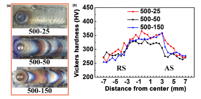
The surface morphologies and hardness profiles of the FSW joints with different heat inputs are shown in Fig. 1. All joints presented similar surface quality and hardness profiles. The NZs were the highest hardness regions. The slightly higher hardness observed in the 500-25 joint might be caused by the shape change in the tool wear band which will be discussed below. No obvious decrease of hardness could be observed in the HAZs. Therefore, high joining strength equal to that of the BM could be obtained, as reported previously [17].
Fig. 1. Surface morphologies and cross-section hardness profiles of FSW HNS joints with different heat-inputs (RS: retreating side; AS: advancing side).
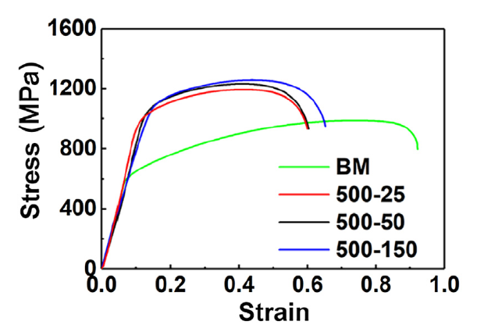
The engineering stress-strain curves of the NZs are shown in Fig. 2. The NZs showed higher strength than the BM and retained a relatively good uniform elongation. The difference in strength between various NZs was very small, which was consistent with the hardness profiles. The NZs of the FSW HNS joints showed good mechanical properties, and at welding speeds of 25-150 mm/min, the heat inputs had little influence on their hardness distribution and tensile strength.
Fig. 2. Engineering stress-strain curves of BM and NZs of FSW HNS joints with different heat-inputs.
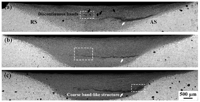
The corrosion morphologies of the joints after pitting immersion corrosion test are shown in Fig. 3. In our previous study, the coarse band-like structure in the bottom layer of each joint was confirmed as tool wear (pointed out by white arrows). In the 500-25 joint, the tool wear band bent upward towards the middle thickness which was attributed to the change in material flow. In the top layer of the 500-25 joint, some small discontinuous bands could be clearly observed which were identified as ferrite (marked by black arrows) [19]. The NZs of the 500-50 and 500-150 joints showed good pitting corrosion resistance with a low density of small pits being observed. However, large pits could be observed in the top layer of the 500-25 joint. It should be noted that in the TMAZs of all FSW joints, a high density of small pits could be observed, especially in the TMAZ of 500-150 joint.
Fig. 3. Pitting morphologies of FSW HNS joints after 48 h of immersion: (a) 500-25; (b) 500-50; (c) 500-150.
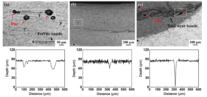
Detailed pitting morphologies of the 500-25, 500-50 and 500-150 joints marked by white frames in Fig. 3 are shown in Fig. 4. As can be clearly observed in Fig. 4(a), narrow dark-etched ferrite bands were formed in the NZ of the 500-25 joint. Large pits with a diameter of about 65 μm and a maximum depth of $\widetilde{2}$ 7 μm were formed near these band-like structures. It was obvious that ferrite in the 500-25 joint was sensitive to pitting corrosion. In the 500-50 joint, only small pits with a diameter of $\widetilde{3}$ 5 μm and a depth of $\widetilde{2}$ 5 μm were formed (Fig. 4(b)). In Fig. 4(c), pits were found near tool wear band of the 500-150 joint with a very large pitting depth of about 85 μm. Clearly, the pitting corrosion behavior of the 500-25 and 500-150 joints showed major difference.
Fig. 4. Detailed pitting morphologies and depth profiles of FSW HNS joints: (a) 500-25; (b) 500-50; (c) 500-150.
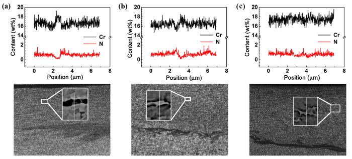
To further explore the reasons of pitting, element distribution profiles of ferrite are given in Fig. 5. Inhomogeneous distribution of Cr and N near ferrite could be clearly observed in the 500-25 and 500-50 joints (Fig. 5(a) and (b)). Enrichment of Cr element in ferrite resulted in a peak in the line scan. Meanwhile, Cr-depleted zones were formed near ferrite. By comparison, more homogeneous element distribution was observed in the 500-150 joint.
Fig. 5. EPMA line scan profiles of element distribution near ferrite in FSW HNS joints: (a) 500-25; (b) 500-50; (c) 500-150.
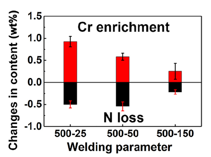
In order to further evaluate the element diffusion near ferrite, the differences between the lowest content and average content of Cr and N elements were calculated. As shown in Fig. 6, with the increase of welding speed, i.e., the decrease of heat-input, the diffusion of Cr was significantly inhibited. Cr, as a ferrite promoting element, has higher solubility and diffusion rate in ferrite than in austenite [9,23]. Thus, the formation of Cr-depleted zone could be predicted. On the other hand, the lowest N content in the 500-25 and 500-50 joints was less than 0.2 wt%. N as an interstitial solution element, has a far faster diffusion rate than substitutional solution Cr element; moreover, the solubility of N atoms is very limited in ferrite phase. Therefore, the diffusion of N atoms was more sufficient. In previous studies, N element was found to have beneficial effects on the corrosion resistance of HNSs [[24], [25], [26]]. Thus, the Cr-depleted zone near ferrite and nitrogen loss were the main reasons of ferrite being sensitive to pitting in the 500-25 joint specimens.
Fig. 6. Comparison between element contents of ferrite in FSW HNS joints.
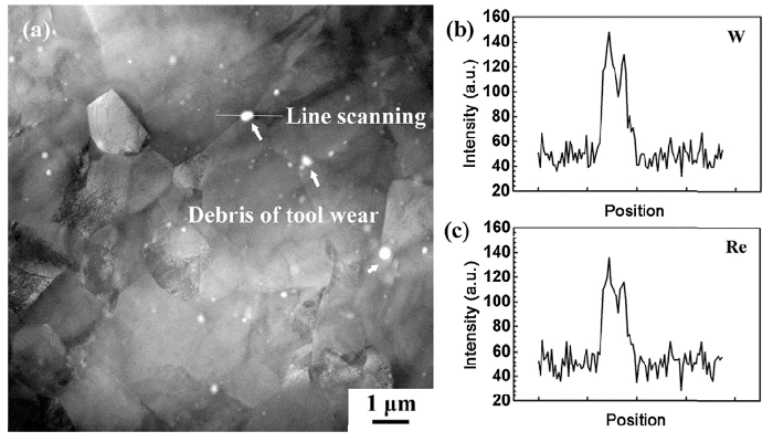
The deterioration of corrosion resistance caused by W-Re alloy tool wear debris may be attributed to two reasons: the difference in corrosion potential between W-Re alloy and HNS and the newly formed phase due to diffusion of W or Re. To clarify the mechanism of corrosion, STEM and EDS were used. In Fig. 7(a), W-Re alloy presents white contrast due to high atomic number in the STEM image. The line scan profiles of the particle are given in Fig. 7(b) and (c). It is clear that tool wear debris was embedded in the matrix, no newly formed phase was found. Therefore, the wear during welding was confirmed as physical wear caused by high flow stress. The cooling rate of FSW was relatively high, and the diffusion of W and Re atoms were very hard due to their atomic number. Thus, the pits near the tool wear band were caused by galvanic corrosion.
Fig. 7. STEM image (a) and EDS line scan profiles (b, c) of tool wear debris in 500-150 joint.
The diffusion of elements and tool wear were both related to the deformation and thermal cycle during FSW. However, the temperature histories in the NZs of the FSW joints were very hard to obtain. In previous studies, simulation methods were applied to achieve the temperature histories in the NZs during FSW based on the temperature data in the HAZs [27,28]. The results showed that, compared to that in the HAZs, the peak temperature in the NZs was higher and the durations at elevated temperature were longer; however, the shapes of the temperature curves in the NZs and HAZs were very similar. This means that it is possible to predict the thermal cycle behavior in the NZs based on experimentally measured temperature curve in the HAZs.
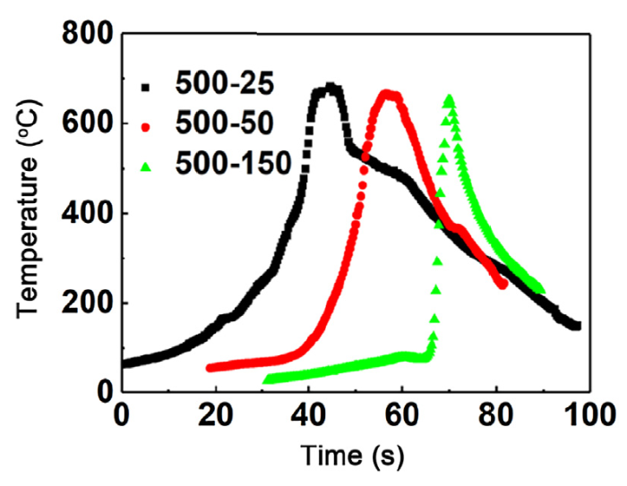
Fig. 8 shows the temperature history profiles of the HAZs in various FSW HNS joints. The peak temperature decreased slightly with increasing the welding speed. However, the high temperature exposing duration showed major difference in three joints. The duration above 400 °C in the HAZ for the 500-25 joint was about four times longer than that for the 500-150 joint. Based on the results of Refs. [26] and [27], it can be predicted that the duration above 400 °C in the NZ for the 500-25 joint was much longer than that for the 500-150 joint. Therefore, the element diffusion near ferrite in the 500-25 joint was more sufficient, resulting in obvious Cr-depleted zones, and the short exposure duration at elevated temperature for the 500-150 joint resulted in a more homogeneous element distribution as showed in Fig. 5, Fig. 6.
Fig. 8. Temperature histories of HAZs in FSW HNS joints.
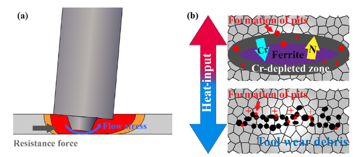
On the other hand, during welding, there were mainly two forces that caused tool wear: the flow stress against the rotating direction and the resistance force against the welding direction (as illustrated in Fig. 9(a)). Due to the same rotation rate, the flow stresses of the various joints should be similar. However, with increasing the welding speed, the resistance force would increase, leading to severe tool wear or even the damage of the tool. The wear debris embedded in the HNS resulted in the initiation of the pits due to the corrosion potential difference.
Fig. 9. Illustration of (a) tool wear and (b) pitting corrosion mechanisms in FSW HNS joints with different heat inputs.
The corrosion behavior of the joints with different heat inputs could be demonstrated by Fig. 9(b). With increasing the heat-input, the duration at high temperature increased, thus the element diffusion was more sufficient. Cr-depleted zones were formed near ferrite resulting in less protective passive film. If the heat-input was too low, severer wear of welding tool could be expected. The increased amount of wear debris led to galvanic corrosion in the corrosion medium, the tool wear band became sensitive to pitting corrosion.
The overall implication of the present study is significant. It shows that although the NZs of the FSW HNS joints exhibited similar tensile properties under different welding speeds from 25 to 150 mm/min, the pitting corrosion resistance of various NZs showed significant difference. Thus, the FSW parameters should be carefully controlled in order to achieve high-performance joints with both good corrosion resistance and excellent mechanical properties.
Different welding parameters were selected to obtain various heat inputs. Effects of heat-input on the corrosion resistance of FSW joints were studied in detail. The following conclusions can be drawn:
(1)Defect-free FSW HNS joints could be achieved under various welding speeds ranging from 25 to 150 mm/min at a constant rotation rate of 500 rpm. The NZs showed higher hardness compared to the BM due to the grain refinement, similar high strength up to about 1200 MPa could be achieved in various NZs with good elongation.
(2)In high heat-input joints, large pits were found around ferrite bands, the extended duration at high temperature led to more sufficient element diffusion. Cr enrichment and N loss could be clearly detected near ferrite bands, the formation of Cr-depleted zones resulted in ferrite being sensitive to pitting corrosion.
(3)In low heat-input joint, severe tool wear could be observed due to the increased resistance force. No new phase was formed near wear debris. Pitting near tool wear band could be attributed to galvanic corrosion.
This work was supported financially by the National Natural Science Foundation of China (Nos. 51671190 and 51471171).
The authors have declared that no competing interests exist.

 WeChat
/
| 〈 |
|
〉 |