

1. Introduction
One of the main benefits of titanium alloys in structural applications is their high specific strength [1]. Especially TB8 with body-centered cubic (BCC) structure, a newly developed metastable β titanium alloy, is attracting considerable attention in aerospace, automotive and medical areas due to the combination of superior properties, including high specific strength, good cold formability, excellent biocompatibility and anti-corrosion characteristics [[2], [3], [4]]. Following the trend of using lightweight metallic material in aerospace, it is envisioned that titanium alloys will gain a much broader range of applications in the future. Therefore, systematic investigation and analysis of the properties of TB8 alloys would help talking more advantage of their potentials.
Currently, more research is focused on the microstructural transformation of TB8 alloy [5,6]; however, fatigue performance of β-type titanium alloys and contribution of their surface state is also of great importance as these classes of materials have been recognized to be susceptible to fatigue damage [7,8]. Fatigue damage is one of the most common failure modes, in which fatigue cracks generally initiate on the surface of metallic materials subjected to cyclic loading, and grow into the interior zones over time, resulting in the final fracture [[9], [10], [11]]. During fatigue cycles, the applied loads can result in changes in the microstructures, surface topography and residual stresses. These aspects are reflected respectively in the formation of microstructural defects, grain size variation, surface roughness and relaxation of residual stresses [[12], [13], [14]]. Therefore, it is necessary to systematically investigate the fatigue behavior of TB8 alloy and effectively control its fatigue damage.
Severe plastic deformation (SPD) techniques have been recognized to efficiently improve the fatigue performance of Ti6Al4V or/and other titanium alloys by modulating their surface properties. Various experimental studies have been conducted to understand the effect of various SPD techniques on fatigue behavior of titanium alloys. Zhao et al. [15] investigated high-cycle fatigue (HCF) behavior of pure titanium treated by equal channel angular pressing (ECAP) and multi-direction forging (MDF). They observed a continuous grain growth induced by room-temperature HCF which was related to the dynamic recrystallization. The stress concentration was relieved via stress-driven grain growth in the pure titanium processed by surface rolling treatment (SRT) during fatigue, thus restricting the initiation of fatigue cracks. Meanwhile, the maximum shear stress and maximum normal stress were decreased due to the superposition of compressive residual stress with the applied stress, resulting in increased fatigue life [16]. Dekhtyar et al. [17] and Kumar et al. [18] worked on the effect of ultrasonic impact treatment (UIT) and ultrasonic shot peening (USSP) on fatigue behavior of Ti6Al4V alloy. Fatigue life of USSP-treated sample was increased four times; and after UIT, fatigue lifetime could be prolonged by two orders of magnitude; the improvements were attributed to reduced surface roughness, compressive residual stress and grain refinement.
Ultrasonic surface rolling process (USRP), a novel surface severe plastic deformation technology, converts alternating current of 25 kHz produced by an ultrasonic apparatus into mechanical vibration with the same frequency, and through a processing tip, applies a pulsating force to the sample surface [[19], [20], [21], [22]]. A rolling cemented carbide ball works as the USRP tip and lubrication oil is introduced into the interface between the tip and the sample surface during the process. Assisted with a control machine, the USRP apparatus can implement precise control of vibration intensity and density, which ensure the repeatability of the process [23]. Combining static force and ultrasonic vibration, USRP is able to improve fatigue life in metallic materials; previous studies have reported improved surface morphology, generation of residual compression stresses, and microstructure refinement after USRP [[24], [25], [26]]. Liu et al. [26] and Zhao et al. [27] investigated the effect of gradient crystalline structure induced by USRP on the fatigue behavior of TC11 and Ti6Al4V alloys. Compared with the as-received materials, the fatigue life improved 23.5 times in the USRP-treated Ti6Al4V; after removing the surface layer which included some defects, the fatigue life further increased up to 113.8 times. The USRP parameters also were found to significantly affect the fatigue strength of titanium alloys [28]. However, there are not much data available on the effect of USRP on the fatigue strength of β-titanium alloys with BCC structure. Additionally, some studies revealed that the fatigue mechanisms could be significantly different for α, β, and α + β titanium alloys [[29], [30], [31]]. This observation indicates that the effect of USRP technique on fatigue behavior of titanium alloys would be varied for different microstructure conditions. Thus, in-depth investigation of the fatigue behavior of TB8 alloys subjected to ultrasonic surface rolling treatment can be of notable impact.
The present work proposed a systematic assessment of the effect of USRP on fatigue performance of TB8 alloy with BCC structure through analyzing residual stress, surface topography and microstructure before and after fatigue on samples treated by different number of USRP passes. Mechanical and microstructural analysis were performed on the samples, including scanning electron microscope (SEM), X-ray diffraction (XRD),Vickers hardness tester and rotating bending fatigue tests. Electron backscatter diffraction (EBSD) was used to analyze the treated samples regarding their microstructure. The results were compared with the authors’ previous work on USRP-treated Ti6Al4V alloy [28]. This comparison helped to provide a better understanding of the effect of materials’ intrinsic properties on fatigue behavior after USRP treatment.
2. Materials and experimental methods
2.1. Materials
TB8 alloy (similar to American titanium alloy β-21S) was delivered as 3 m rolled bar with a diameter of 16 mm, heat treated at 830 °C for 0.5 h, and subsequently air cooled. Fig. 1(a) shows the microstructure of the as-received base material (BM) that consisted of a single phase of β. The chemical composition of TB8 alloy is reported in Table 1. EBSD was applied to analyze the grain size and crystallographic texture of the samples. Fig. 1(b) shows an inverse pole figure (IPF) map of the BM. The analysis showed that the β phase with BCC structure was characterized with equiaxed grains. The average equivalent grain size from the area of each grain ($\text{d}=2\sqrt{Area/\pi }$) was approximately measured to be 34.2 μm, in which the grains were defined with a misorientation angle above 15°. Fig. 1(d) present the (001), (110) and (111) pole figures, and the IPF map is shown in Fig. 1(e). The BM exhibited only a relatively weak texture on the (111) pole figure, parallel to the TD1 direction, with an intensity value close to 4. The stress-strain (σ-ε) curve is depicted in Fig. 1(c), and the corresponding mechanical properties, including the ultimate tensile stress (UTS), 0.2% offset proof stress (σ0.2) and tensile ductility (εf), are listed in Table 2. The toughness (UT) was estimated via integrating the area under the σ-ε curves, and the corresponding strain hardening exponent (n) value was determined by the equations presented in [32], where n was related with the true initial yield stress, strengthening coefficient, strain and stress. TB8 alloy used in this work exhibited excellent plastic property.
Fig. 1.

Fig. 1.
(a) Microstructure of the base TB8 alloy, (b) EBSD image with IPF color coding, (c) Stress-strain curve obtained from the base material, (d) (001), (110), and (111) pole figures obtained from examining the axial-sectional plane, (e) Inverse pole figure along the TD1 direction.
Table 1 Chemical composition (wt%) of TB8 alloy.
| Position | Al | Si | Nb | Mo | Ti |
|---|---|---|---|---|---|
| a | 3.29 | 0.21 | 2.88 | 15.10 | balance |
| b | 3.22 | 0.19 | 2.82 | 14.95 | balance |
| c | 3.27 | 0.19 | 2.90 | 15.22 | balance |
Table 2 Mechanical properties of the base TB8 alloy.
| Sample | UTS (MPa) | σ0.2 (MPa) | εf (%) | UT (J/cm3) | n |
|---|---|---|---|---|---|
| TB8 | 891.3 | 855.87 | 26.0 | 218.4 | 0.40 |
2.2. USRP and fatigue testing
The sample considered for the rotating bending fatigue test is shown in Fig. 2(b). The markup segment (dark cyan) was longitudinally polished using a machine tool before the USRP treatment to this segment. A detailed description of USRP was available in some of the authors’ previous work [22]. It is known that the combination of a static force with the ultrasonic technology, as shown in Fig. 2(a), would enhance the efficiency of the process. A vibration frequency of 25 kHz was applied to induce severe plastic deformation in all the series. For each sample, different USRP parameters such as lath rotational speed, feeding rate, and static force were used to deform the material, to attain the optimal USRP parameters. Initially, a PQ-6 type rotating-bending fatigue test was performed on limited number of samples to identify the most promising set of parameters [26]. The relevant results are presented in Table 3. Sample 6 was found to possess the highest fatigue life among the tested series; thus, the corresponding USRP parameters were applied to prepare the test samples for the rest of the analysis. The samples used to obtain the fatigue strength were subjected to one, five and fifteen number of passes using the optimal USRP parameters. Hereafter these series were referred to USRP-1, USRP-5 and USRP-15, respectively.
Fig. 2.

Fig. 2.
Schematic diagrams of (a) USRP set-up, (b) fatigue sample.
Table 3 USRP parameters and the corresponding fatigue lives in the initial tests performed (at a maximum stress amplitude of 450 MPa) to identify the optimized parameters.
| Sample number | Lathe rotational speed (r/min) | Feed rate (mm/rev) | Static stress (MPa) | Fatigue life (cycle) |
|---|---|---|---|---|
| 1 | 55 | 0.08 | 480 | 85853 |
| 2 | 55 | 0.10 | 630 | 99228 |
| 3 | 55 | 0.12 | 780 | 66395 |
| 4 | 75 | 0.08 | 630 | 91504 |
| 5 | 75 | 0.10 | 780 | 68176 |
| 6 | 75 | 0.12 | 480 | 176080 |
| 7 | 95 | 0.08 | 780 | 57918 |
| 8 | 95 | 0.10 | 480 | 110210 |
| 9 | 95 | 0.12 | 630 | 75084 |
Rotating bending fatigue tests of un-treated and USRP-treated TB8 samples were performed on an Italsigma (IT) machine under a rotational speed of about 2000 rpm and a stress ratio R=-1 at room temperature. The staircase (up and down) method was carried out on each series of samples with a step size of 20 MPa [33]. The samples were considered run-out when survived by 3 × 10⁶ cycles, and the corresponding fatigue strength was calculated using the statistic approach suggested in ISO12170.
2.3. Surface and microstructural characterization
The axial-sections of BM, USRP-treated and post-fatigued samples were polished (mechanical and ion polishing) for EBSD analysis. EBSD tests were conducted on a TESCAN MAIA3 scanning electron microscope equipped with an OXFORD EBSD detector. To attain appropriate multiple high-quality figures, step sizes ranging from 0.25 to 1.5 μm were selected. The obtained raw data was analyzed with Channel 5 and OIM softwares. The boundaries with misorientations below 15° were regarded as low angle grain boundaries (LAGB) and those above 15° were defined as high angle grain boundaries (HAGB) or grains.
The surface morphologies of post-fatigued samples, and the cross-sectional microstructures were observed via SEM on a JSM-63,390 instrument. Surface morphology and fracture morphologies of BM and USRP-treated samples were checked by a Zeiss EVO 50 SEM. Surface roughness of BM and USRP-treated samples were measured using a Mahr Perthometer equipped with MFW-250 probe with a tip diameter of 5 μm. These measurements were carried out three times for each series, and the average values of roughness parameters such as arithmetic mean of the absolute ordinates (Ra), root mean square of the ordinates (Rq) and the mean of the largest peak height and the largest valley depth (Rz) were obtained.
Phase-compositions in the samples before and after USRP treatments were detected via X’pert-PRO XRD. Additionally, the in-depth distribution of residual stresses along the radial direction in the USRP sample and the surface residual stress of post-fatigued samples were analyzed using AST X-Stress 300 portable XRD instrument with TiKα radiation (λ = 2.74973 Å). The sin2ψ method was applied at a diffraction angle (2θ) of 137.4° and the incident angles varying between 0°, -24.1°, -35.3°, -45°, 24.1°, 35.5°, 45° and 90°. Electro-polishing was used for removing the materials using solution of acetic acid (94%) and perchloric acid (6%).
In-depth distribution of micro-hardness on the axial-section of the samples before and after USRP was measured using a Leica WMHT30A micro Vickers hardness tester. The indentations were formed using a load of 10 gf and dwell time of 15 s; three measurements were performed at each depth below the treated surface, the average values of which were reported.
3. Results
3.1. Microstructure and micro-hardness
EBSD characterization of axial-section of the USRP samples confirmed the surface grain refinement and the gradient microstructure in the surface layer, as indicated in Fig. 3. The grain size presented a slight growth in the surface region of USRP-1 sample (Fig. 3(a)); it was postulated to be associated with defect annihilation caused by high vibration frequency and poor thermal conductivity [34,35]. For USRP-5 sample, there began to appear a few small grains on the surface, while the proportion of small grains increased on the surface of USRP-15 sample. The gradient microstructure formed in the USRP-15 sample was measured up to a depth of 240 μm, as shown in Fig. 3(d, e). In this sample, the small grains in the depth about 280 μm could be due to the pre-heat treatment that was also found in other samples (see point 1 in Fig. 1(a) and Fig. 3(a)). In addition, the boundary distribution (BD) figures shown in Fig. 3(a, c, e and f) indicated that the LAGB gradually increased and finally translated into HAGB, thus refining the grains [36]. Fig. 3(g, h) present (001), (110) and (111) pole figures and inverse pole figure of USRP-15 sample. It could be seen that the material exhibited relatively weak textures on the (111) and (100) pole figures with an intensity value close to 4, in which the texture of USRP-treated sample was not obvious change compared with the BM.
Fig. 3.

Fig. 3.
(a) EBSD image with BD map of USRP-1sample, (b) IPF of USRP-5sample, (c) BD map of USRP-5 sample, (d) IPF of USRP-15sample, (e) BD map of USRP-15 sample, (f) BD map of the base material, (g) (001), (110), and (111) pole figures obtained from examining the axial-section plane of USRP-15 sample, (h) Inverse pole figure along the TD1 direction of USRP-15 sample.
As shown by the XRD spectra in Fig. 4(a), no new phases were found in the samples’ surface layers, and the peak positions of β phase in the USRP processed samples were slightly shifted compared to BM sample because of the lattice distortion [37]. However, the relative intensity of crystallographic planes showed no significant change, implying no obvious texture formed after USRP, which is in agreement with the results of Fig. 3. Fig. 4(a) demonstrates a gradient distribution of micro-hardness in the USRP samples. The surface hardness increased from the initial value of about 240 HV (BM) to 410 HV (USRP-15) at the topmost surface. The micro-hardness of USRP-15 sample reduced gradually with increasing the depth below the processed surface, reaching that of the BM at approximately 215 μm. Besides, the surface micro-hardness and the depth of hardening gradually increased as the number of USRP processing passes increased. The surface hardness was about 280 HV for USRP-1 and 330 HV for USRP-5 samples, respectively; this could be attributed to the variation in their microstructure such as grain size, dislocation density and residual stresses [[38], [39], [40]].
Fig. 4.

Fig. 4.
(a) Surface phase compositions (b) Variations of Vickers microhardness along the depth from the USRP processed surface.
3.2. Surface roughness
The surface morphologies and surface roughness of BM and USRP samples are analyzed and compared in Fig. 5. The BM sample’s surface exhibits mechanical polishing traces that are characterized by grooves perpendicular to the applied load, representing roughness parameters of Ra = 0.4 μm and Rz = 2.5 μm. After USRP treatment, these traces gradually vanished (see Fig. 5(b-d)). The surface could be regarded as relatively “smooth” for the USRP-5 sample, which was characterized by a decreased surface roughness (Ra = 0.05 μm and Rz = 0.5 μm). The smooth surface could be attributed to the combined effect of oil lubrication, ultrasonic vibration and static force application during the USRP treatment [1]. For the USRP-15 samples, on the other hand, the surface roughness increased to Ra = 0.075 μm and Rz = 0.6 μm because of the surface damage induced by excessive number of USRP passes.
Fig. 5.

Fig. 5.
Surface morphologies of (a) BM, (b) USRP-1, (c) USRP-5, and (d) USRP-15 samples, (e) The corresponding surface roughness of TB8 alloy and USRP samples.
3.3. Fatigue behavior
The staircase (up and down) method was used to assess the fatigue strength corresponding to a life of 3 × 10⁶ in stress-controlled tests (Table 4). As indicated in Table 5, USRP increased the fatigue strengths of the samples. The fatigue strength increased from 295 MPa for BM sample to 335 or 338 MPa for USRP-1 and USRP-5 series. The USRP-15 samples showed the same results as USRP-1 series. The general increment in terms of fatigue strength was found to be very similar for all the three series without any meaningful statistic difference, and estimated to be around 14%.
Table 4 The stress levels and corresponding fatigue lives (3 × 10⁶ run-out).
| BM | USRP-1 | USRP-5 | USRP-15 | ||||
|---|---|---|---|---|---|---|---|
| Stress (MPa) | Cycle | Stress (MPa) | Cycle | Stress (MPa) | Cycle | Stress (MPa) | Cycle |
| 280 | 3000000 | 320 | 3000000 | 320 | 3000000 | 320 | 3000000 |
| 300 | 2697789 | 340 | 1141318 | 340 | 3000000 | 340 | 1149526 |
| 280 | 3000000 | 320 | 3000000 | 360 | 1039376 | 320 | 3000000 |
| 300 | 3000000 | 340 | 3000000 | 340 | 3000000 | 340 | 1369957 |
| 320 | 189967 | 360 | 621385 | 360 | 1267542 | 320 | 3000000 |
| 300 | 386545 | 340 | 829649 | 340 | 2082442 | 340 | 3000000 |
| 280 | 3000000 | 320 | 3000000 | 320 | 3000000 | 360 | 783116 |
| 300 | 429000 | 340 | 931604 | 340 | 1723102 | 340 | 1149526 |
| 280 | 3000000 | 320 | 3000000 | 320 | 3000000 | 320 | 3000000 |
Table 5 Fatigue strength calculated by ISO12017 method.
| Sample | Fatigue strength (MPa) (ISO12017) |
|---|---|
| BM | 295 ± 7 |
| USRP-1 | 335 ± 7 |
| USRP-5 | 338 ± 8 |
| USRP-15 | 335 ± 7 |
A second assessment of the effectiveness of the proposed treatments was done considering the fatigue life when the same stress was applied. In this case, maximum stress levels of 340 MPa and 360 MPa were chosen to figure out the effect of the number of USRP passes on the fatigue life of TB8 alloys, as indicated in Fig. 6. In comparison with BM samples, the fatigue lives under a maximum stress level of 360 MPa were enhanced approximately 2.30-, 4.82- and 3.29-fold for USRP-1, USRP-5 and USRP-15 samples, respectively. In addition, it also could be seen from the results under a maximum stress level of 340 MPa that the USRP-5 series exhibited the highest fatigue life, showing a 4.90-fold improvement. That is to say, five passes were found to be the optimum processing condition for these USRP parameters.
Fig. 6.
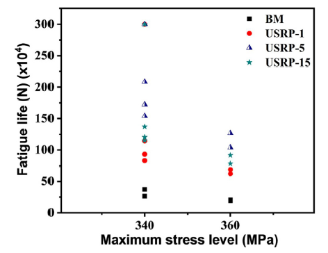
Fig. 6.
Comparing the fatigue lives of BM and USRP-treated samples under maximum stress levels of 340 MPa and 360 MPa.
The fracture surfaces of BM and USRP samples and the corresponding elaborated data are demonstrated in Fig. 7. A single fatigue crack initiation site was detected on the surface of BM sample, as shown in Fig. 7(a, a1). USRP was found efficient in displacing the location of fatigue crack initiation toward the interior of sample; the depth of the crack initiation site and the corresponding actual stress are shown in Fig. 7(f). The results indicated that for the USRP-5 sample, the crack initiated at a higher depth where the corresponding actual applied stress was the lowest. Many factors, such as residual stress, surface defect, microstructure, and micro-hardness, could act synergistically to cause the shift of fatigue crack initiation site toward the inner layer of material, leading to the improvement of fatigue life [28]. This is valid about the results obtained in this work where the USRP-5 sample possessed the highest fatigue life, exhibiting the deepest crack initiation site. In addition, it is possible to notice that the fatigue strength was higher than the actual applied stress at the initiation point, when the crack initiation was located in sub-surface regions (USRP samples), and the fatigue strength was lower than the actual applied stress for the sample in which the crack initiated from the surface (BM sample).
Fig. 7.

Fig. 7.
Fracture surface morphologies under a maximum stress level of 340 MPa of (a, a1) BM, (b, b1) USRP-1, (c, c1) USRP-5, (d, d1) USRP-15, (e) The schematic figure for calculating the actual stress at the crack initiation point, (f) Graph representing the depth of crack initiation and the corresponding calculated actual stress at the initiation point.
4. Discussion
4.1. USRP effects on fatigue property of titanium alloy
Improved fatigue properties, i.e. higher fatigue strength and fatigue life in the stress-controlled fatigue tests, were observed in all USRP-processed TB8 alloy samples in comparison with the BM series. The fatigue strength (corresponding to 3 × 10⁶ cycles) was enhanced by ~14% in all USRP samples, and the fatigue life was estimated to be 2.30 (USRP-1), 4.82 (USRP-5) and 3.29 (USRP-15) times that of un-treated TB8 sample at a stress level of 360 MPa. This is very different from what was observed for the case of Ti6Al4V alloy treated by USRP technology, i.e. significantly enhanced fatigue strength or fatigue life [26].
For analyzing the relations among USRP parameters, microstructural condition and fatigue properties, the fatigue test results of different titanium alloys treated by USRP were summarized in Table 6. It can be seen that the fatigue strength or fatigue life are effectively improved by USRP technology, in all cases. However, compared to the remarkably improved fatigue strength and fatigue life in other titanium alloys processed by USRP technology, it is noticed that the improvement degree of USRP-treated TB8 alloy is not noticeable. Even if larger compressive residual stresses were introduced in the surface of TB8 samples, their fatigue life and fatigue strength improvement would still be lower than that of USRP-treated Ti6Al4V samples, despite the similar surface morphology and microstructure induced (no notable gradient microstructure) in both materials [28]. This phenomenon could be attributed to the intrinsic properties of the metallic material itself, including microstructure, crystal structure (slip system) and mechanical properties. Ti6Al4V has a dominant α phase microstructures with close-packed hexagonal (HCP) structure and β phase with BCC structure. Compared to the BCC structure, fewer slip systems are available in HCP structure in which dislocations are not easy to move and compressive residual stress induced by USRP has high stability, thus decreasing the rate of crack initiation and propagation [41].
Table 6 The effect of USRP on fatigue life of different titanium alloys.
| Materials | Thickness (μm) (deformation layer) | The related residual stress | Fatigue test conditions | Fatigue results (improvement degree compared with BM) | Reference | ||
|---|---|---|---|---|---|---|---|
| Maximum (MPa) | Depth (μm) | Fatigue strength | Fatigue life | ||||
| Ti6Al4V | __ | -963 | 550 | Rotating-bending fatigue R=-1 | 39% (1 × 10⁷) | 295-fold | [28] |
| Ti6Al4V | 335 | -1155 | 650 | Rotating-bendi ng fatigue R=-1 | 22% (1 × 10⁷) | 24.5-fold | [26] |
| HIP-Ti6Al4V | 20 | -1173 | — | Rotating-bending fatigue R=-1 | 25% (1 × 10⁷) | — | [64,65] |
| TC11 | 70 | -898 | 200 | Tension-tension fatigue R=0.1 | 19.3% (5 × 10⁶) | — | [66] |
| TB8 | — | -1200 | 550 | Rotating-bending fatigue R=-1 | 14.6% (3 × 10⁶) | 4.95-fold | Present work |
4.2. Fatigue mechanisms
Enhanced fatigue strength or fatigue life of TB8 alloy was affected by microstructure, residual stress and roughness. The underlying fatigue mechanism will be described and discussed in detail in the following paragraphs.
(1) The larger grains in the BM sample increased the possibility of crack initiation, resulting in lower fatigue life. Moreover, the higher number of LAGB and HAGB in the USRP treated samples increased the deformation homogeneity of grains (grain growth) and impeded the crack initiation and propagation, thus improving their fatigue life (see Fig. 8, Fig. 9, Fig. 10 in section 4.2.1) [42].
Fig. 8.

Fig. 8.
(a) EBSD image with IPF, (b) Schmid factor map, (c) Phase distribution of USRP-5sample after fatigue test under a maximum stress level of 340 MPa.
Fig. 9.

Fig. 9.
(a) EBSD image with BD map of pre-fatigue USRP-15 sample, (b) BD map of post-fatigued USRP-15 sample under a maximum stress level of 340 MPa, (c) and (d) The corresponding grain size distribution figures of pre-fatigue USRP-15 and post-fatigued USRP-15 samples, respectively.
Fig. 10.

Fig. 10.
EBSD image with KAM maps in (a) pre-fatigue USRP-15 sample, (b) post-fatigue USRP-15 sample under a maximum stress level of 340 MPa; KAM distributions in (c) pre-fatigue USRP-15 samples, (d) post-fatigue USRP-15 sample under a maximum stress level of 340 MPa.
(2) Compressive residual stresses induced by USRP reduced the effective applied tensile stress and stress intensity factor range at the crack tip, thus resulting in delaying crack initiation and propagation (Fig. 11 in section 4.2.2) [[43], [44], [45]]. USRP treatment drove the fatigue source to sub-surface layer of TB8 alloy, indicating that compressive residual stress played an important role in controlling fatigue damage [28].
Fig. 11.

Fig. 11.
(a) and (b) EBSD images with KAM maps and the corresponding derived fractions for BM and USRP samples, (c) In-depth residual stress distributions in BM and USRP samples, and (d) The surface residual stress of pre- and post- fatigued USRP-5 sample.
(3) The higher surface roughness presented in the pre- and post- fatigued BM samples, namely mechanical polishing traces, surface extrusion and intrusion, promoted surface crack initiation, thus decreasing the fatigue life (Figs. 5 and Fig. 13 (section 4.2.3)).
4.2.1. Fatigue crack initiation and propagation
Microstructure evolution during fatigue loading is expected to affect crack initiation and propagation [15]. Fig. 8 presents an example of small fatigue crack observed on the axial-section of post-fatigued USRP-15 sample. The crack initiated on grain I ([001] plane) with a high Schmid factor, confirming the results obtained via quantitative analysis of crack initiation sites [47]. The size of grain I was larger than others like grain V in the surface region, which could cause a higher probability for crack initiation, described via using Tanaka-Mura model [48]. In comparison with BM sample indicated in Fig. 3(f), the smaller grain size in USRP-15 (Fig. 3(e)) could significantly inhibit the crack initiation. The initiated crack propagated along nearly 45°, went through the large grain II of BCC β-phase, after which a more than 90° direction change appeared in the grain III and IV ([111] plane); the latter could be attributed to the crystallographic orientation and stress compatibility [49]. In addition, the α precipitates formed via USRP could cause local stress concentration, which would affect the crack initiation and propagation [50].
The pre-fatigue USRP-15 sample had an average grain size of 16.4 μm, which increased to about 22.5 μm after fatigue test under a maximum stress level of 340 MPa, as indicated in Fig. 9 (c, d). The fraction of HAGB reduced from 22.9%-13.2%, and the fraction of angle below 5° increased from 66.9%-83.8%, after fatigue tests. That is to say, the crack propagation caused the reduction of HAGB, thus promoting grain growth at room temperature, which was related to the dislocation motion [51]. Grain growth phenomenon was observed near the crack surfaces of ultra-fine copper [52], which seemed to be explained by the crucial role of cyclic stresses [53]. However, Zhao et al. reported that thermally activated continuous recrystallization was a factor in induced grain growth of ultrafine-grained pure titanium under HCF [15]. These (driving forces) had a significant relationship with the thermal conductivity of materials. In this regard, the thermal conductivity of TB8 alloy is 15.2 W/mK and that of pure titanium is 17 W/mK, which were both much lower than that of copper. This indicated that the TB8 alloy would be easy to warm during the fatigue loading.
The geometrically necessary dislocations (GND) can be considered as important evidence to estimate whether the thermally activated dynamic recrystallization occurred during the fatigue test or not. The kernel average misorientation (KAM) maps of pre- and post- fatigued USRP-15 samples are shown in Fig. 10. The Average KAM value was estimated to be 1.905 for USRP-15 sample and 0.269 for fatigued USRP-15 sample. The following equation was applied to calculate the GND density [54]:
where ρGND is the GND density, KAMav represents the average of KAM, μ is the unit length of the point, and b is the Burgers vector. For the TB8 alloy with BCC structure, the b magnitude of 0.286 nm was used in this work. In the surface region, a reduced average GND value of 7.54 × 10¹⁵ m-2 was obtained for the post-fatigue USRP-15 samples (at a maximum stress level of 340 MPa) compared to 8.88 × 10¹⁵ m-2 for the same series before fatigue test. This trend indicated that dynamic recrystallization caused grain growth after fatigue in TB8 alloys treated by USRP.
4.2.2. Residual stresses
Residual stresses are known to affect the crack initiation and propagation via changing the local maximum stress intensity factor and crack growth threshold value [55,56]. Thus, improved fatigue strength is expected in the samples with prominent compressive residual stresses. Different impact-based surface treatments that induce compressive residual stresses through severe plastic deformation such as severe shot peening (SSP), UIT and USRP, which are reported to considerably enhance fatigue performance of different materials [[57], [58], [59]].
In the present work, significant compressive residual stresses were generated in the deformed layer of USRP-treated samples. The KAM values could be used to describe the extension of deformation that was directly related to the compressive residual stresses, as shown in Fig. 11 (a, b). The KAM values were estimated to be 0.53 for BM, 0.65 for USRP-1, 0.67 for USRP-5, and 0.95 for USRP-15 samples; this indicated the highest extent of deformation to have been induced in the latter series. For a more accurate analysis, XRD residual stress measurements were performed, as indicated in Fig. 11(c). The depth of layer affected by compressive residual stresses increased as the number of USRP passes increased. This parameter was estimated for USRP-15 series to be approximately 550 μm. For these samples, the highest compressive residual stress of 1300 MPa was measured at the depth of 150 μm, which gradually decreased with increasing the depth. A similar distribution of compressive residual stresses was measured in USRP-1 and USRP-5 samples, in which the maximum stresses were about -800 MPa and-1200 MPa, respectively. However, for the BM sample, the highest compressive residual stress was about 100 MPa on the surface. After the fatigue tests, the surface residual stress of USRP-5 sample decreased from -384.5 MPa to-157.3 MPa at a maximum stress level of 340 MPa and to 26.5 MPa at a maximum stress level of 360 MPa. It could be noticed that the residual stress exhibited a significant reduction, which meant the contribution of compressive residual stress to improve the fatigue life of TB8 alloys reduced.
4.2.3. Evolution of surface morphology
Except for the compressive residual stresses, surface roughness also was an important factor affecting the fatigue strength. Sang et al. [60] and Long et al. [13] reported that the surface roughness of pre- and post-fatigued samples were critical factors in the initiation and growth of fatigue crack. In the present work, the lowest surface roughness was observed on USRP-5 samples (Fig. 5(c, e)), which would reduce the number of crack initiation sites in comparison with BM samples. Thus, “smoother” surface and larger compressive residual stresses resulted in the highest fatigue lives tested at stress levels of 360 MPa and 340 MPa for USRP-5 series. However, the increased surface roughness in USRP-15 samples implied that some defects might be formed during the USRP process. As shown in the top surface observation of the USRP-15 samples’ surface (see Fig. 12), few folding defects could be detected. These defects are considered to have resulted in the relaxation of surface residual stresses compared to the USRP-5 sample (Fig. 11(c)). This stress relaxation could have contributed to the decreased depth of fatigue crack initiation, and the reduced fatigue strength for the USRP-15 samples.
Fig. 12.
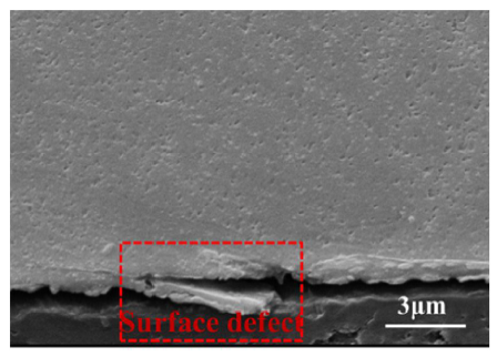
Fig. 12.
A representative surface defects of USRP-15 sample.
Fig. 13.
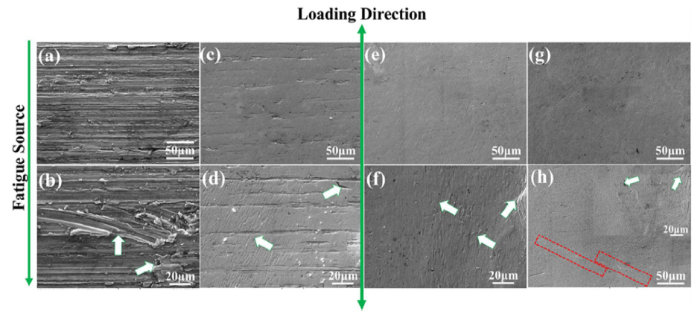
Fig. 13.
Surface morphologies of BM and USRP samples after fatigue tests under a maximum stress level of 340 MPa of (a, b) BM, (c, d) USRP-1, (e, f) USRP-5 and (g, h) USRP-15 sample.
SEM surface micrographs of the post-fatigued BM samples demonstrated signs of cracking and delamination that resulted from surface extrusion and intrusion away from and also near fatigue crack initiation sources, compared with Fig. 13(a, b) and Fig. 5(a). High surface roughness induced by fatigue would act as the sites of crack initiation because of the stress concentration, leading to fatigue damage and eventually failure [61]. For all USRP processed samples, the phenomenon of surface extrusions and intrusions were not identified near fatigue crack source, and no apparent surface delamination was observed at these post-fatigued samples’ surfaces (see in Fig. 13(c-h)). These observations implied that the reduction of surface stress concentration in USRP samples under fatigue loading resulted in improved the fatigue life. On the other hand, the surface of USRP-15 sample, after fatigue test, was “smooth” with few surface defects compared to the other series, indicating that the plastic deformation was impeded due to the highest hardness [62,63]. The surface roughening mechanism of post-fatigued BM sample and fatigue failure were restrained in the USRP processed samples because of the induced severe plastic deformation that caused compressive residual stress, grain refinement, microstructural alteration and increased near-surface micro-hardness.
5. Conclusion
TB8 alloy samples were subjected to ultrasonic rolling process in order to induce severe plastic deformation on the top surface layer of the material. The process parameters were optimized through preliminary rotating bending fatigue tests. The samples were treated using the optimized set of parameters for 1, 5 and 15 passes (respectively called USRP-1, USRP-5, and USRP-15). The samples were experimentally characterized regarding microstructure, residual stress and surface topography before and after fatigue tests. The main findings of the characterizing tests are summarized as follows:
(1) A gradient structure surface layer was produced on TB8 titanium alloy by means of USRP performed at room temperature. The different number of passes resulted in variations in the microstructure, compressive residual stresses, micro-hardness, and surface roughness on USRP-1, USRP-5, and USRP-15 samples.
(2) Stress-controlled fatigue tests indicated improved fatigue properties in USRP samples. A 14% fatigue strength enhancement corresponding to 3 million numbers of cycles was observed after USRP in all series compared to the base material. The fatigue lives respectively enhanced 2.30-, 4.82- and 3.29-folds for USRP-1, USRP-5 and USRP-15 series in comparison with the base material at an assigned maximum stress level of 360 MPa. The fractographic analysis revealed that the fatigue crack initiation sites were displaced from the surface (observed in case of base material series) to the sub-surface layer after USRP; in all USRP series the cracks initiated at depths beyond the thickness of layer affected by treatment. The high compressive residual stresses, “smooth” surface and refined microstructure induced by USRP were considered to significantly contribute to the improved fatigue life. In addition, surface defects induced on the surface of USRP-15 sample, due to the high number of passes, were found to reduce the depth of fatigue initiation site and the corresponding fatigue life.
(3) Post-mortem analysis of fatigue tested TB8 samples indicated that the fatigue crack initiation occurred in the larger grains with high Schmid factor; the cracks then propagated in the small crack along nearly 45° in a mixed transgranular and intergranular manner. Meanwhile, the reduced fraction of HAGB after fatigue tests (from 22.9%-13.2%) indicated grain growth in USRP treated series, highlighting that the dynamic recrystallization played a crucial role.
(4) The extent of fatigue properties improvement obtained from the application of USRP technology for the TB8 alloys was not as significant as it was reported for other titanium alloys (i.e. Ti6Al4V); this implied the importance of the choice of USRP parameters in relation with the elasto-plastic response of the target alloy.
Acknowledgments
DL, DXL, XXC and KFF greatly appreciate the support of National Natural Science Foundation of China (51771155), National Science and Technology Major Project (2017-VII-0012-0107) and Equipment Pre-research Field Fund (61409220202).
Reference
DOI
URL
PMID
[Cited within: 1]

The technology of ultrasonic vibration assisted plastic forming possesses a great many merits, such as reducing the deformation resistance and friction, as well as improving the surface quality of parts. In this study, the ultrasonic vibration assisted compression tests were carried out on pure titanium in order to improve its formability. The results indicating that the ultrasonic vibration had no effort on elastic deformation, and the temperature of material only increased by 6 degrees C after compression with applying the ultrasonic vibration. Therefore the influence of temperature increase on reduction of flow stress could be ignored. After excluding interface friction and temperature effects, ultrasonic vibration can still decline the flow stress, the mechanism of deformation includes ultrasonic softening, stress superposition and strain hardening. In the intermittent vibration tests, the material shows the residual softening effect after stopping vibration. By observing the microstructure of material with SEM, it shows that the ultrasonic vibration can promote the generation of deformation twins, causing the grain refinement and the reduction of the twins, which is the major factor of affecting the residual softening effect.
AbstractThe strength of room temperature rolled sputter deposited nanolayered Cu–Nb composites is evaluated. Self-supported Cu–Nb foils with initial individual layer thickness varying from 32 to 75 nm were rolled to the same final layer thickness of 30 nm. Nanoindentation hardness measurements were used to study the change in hardness with rolling strain. The resulting work hardening rate is compared to bulk Cu and mechanisms that give rise to work hardening in nanolayered metals, in the absence of dislocation cell structure formation, are discussed.]]>
DOI
URL
PMID
[Cited within: 1]
Pure iron and its biocompatible and biodegradable alloys have a high potential to be used for temporary load bearing medical implants. Nevertheless, the formation of passive iron oxide and hydroxide layers, which lead to a considerably low degradation rate at the physiological environment, has highly restricted their application. Herein we used numerical and experimental methods to evaluate the effect of severe shot peening, as a scalable mechanical surface treatment, on adjusting the performance of pure iron for biomedical applications. The developed numerical model was used to identify the range of peening parameters that would promote grain refinement on the pure iron surface. Experimental tests were then performed to analyze the gradient structure and the characteristics of the interface free surface layer created on peened samples. The results indicated that severe shot peening could notably increase the surface roughness and wettability, induce remarkable surface deformation and grain refinement, enhance surface hardness and generate high in-depth compressive residual stresses. The increased surface roughness besides the high concentration of micro cracks and dislocation density in the grain refined top layer promoted pure iron's degradation in the biologically simulated environment. STATEMENT OF SIGNIFICANCE: Biodegradable metallic materials with resorbable degradation products have a high potential to be used for temporary implants such as screws, pins, staples, etc. They can eliminate the need for implant retrieval surgery after the damaged tissue is healed, and result in reduced patient suffering besides lowered hospitalization costs. Pure iron is biodegradable and is an essential nutrient in human body; however, its application as biomedical implant is highly restricted by its slow degradation rate in physiological environment. We applied a scalable surface treatment able to induce grain refinement and increase surface roughness. This treatment enhances mechanical performance of pure iron and accelerates its degradation rate, paving the way for its broader applications for biomedical implants.

 WeChat