


1. Introduction
The surging field of polymer bonded carbon nanotubes (CNTs) has provided promising opportunities for transferring inherent properties of CNTs into macroscopic applications in composite materials [[1], [2], [3]], sensor [4,5], electric drive technology [6], and thermal insulator [7], etc. The incorporation of CNTs into polymer matrix has guaranteed great potential development of super-strong and super-stiff polymer-based composites. In addition, according to the modification processes [8,9], it is a well-known strategy to employ CNTs as filler for reinforcing polymer matrix for fabrication of functional composites, such as unique electric, light and thermal properties [3]. However, the main barriers for CNTs as filler particles are the dispersion and alignment in polymer matrix [5]. CNTs can be bundled and intertwined together and form bulk block in polymer matrix due to the high length-diameter ratio and anisotropic properties [8]. This may weaken the reinforcement function and dispersity of CNTs in polymer matrix, and further decrease the stability and other properties of composite. The selection of proper polymer matrix and decoration of CNTs surface [9] are the two main ways to solve the problem. The decorated CNTs with a low loading, which dispersed relatively homogenous in the polymer matrix, can be fabricated by solution casting, in situ polymerization or ultrasonication for a long time [10].
Poly(lactide) (PLA) is one of the most promising environment-friendly polymers, which possesses attractive mechanical properties, renewability, biodegradability and relatively low cost [11]. Although PLA has these merits, it is brittle with low impact strength, thermal and electric properties, representing the main limitations for the sustainable development in industries [8]. The addition of CNTs filler into PLA matrix is one of the most significant strategies to improve the performance. The most straight forward method remains the direct melt-extrusion blending [8] of CNTs with PLA matrix via twin-screw extruder or single screw extruder. It is reported that the dispersion extent of CNTs within PLA matrix using extrusion technology is affected by the melt-mixing conditions largely, including different screw profile, temperature profile, rotation speed and so on [12]. Murr et al. [13] mixed CNTs and PLA physically and then the mixture was extruded by using a counter-rotating twin-screw mini-extruder. The addition of CNTs can obviously improve the PLA properties due to the strong interfacial interaction between the CNTs surface and the PLA chains. Villmow et al. [14] also prepared graphene nanoplatelet/PLA composite via melting process by using an internal mixer. The results indicated that the incorporation of graphene nanoplatelet improved the crystallinity from 29.6 %-41.9 %, thermal stability, Young’s modulus, and electrical conductivity of PLA. According to the previous [15], the introduction of CNTs into PLA matrix helps to form electrospun fibers made of PLA. It is suggested that the CNTs/PLA composite may be used as raw materials in other fabrication methods, such as electrospun, and three-dimension (3D) printing [16,17]. Moreover, the CNTs/PLA composite may be significantly applied in scaffold for tissue, water treatment, textile, packaging and even flexible electronic devices [[18], [19], [20]]. Thus, it is significant to prepare CNTs/PLA composite-based molding with different functions to broaden their application.
For preparation of CNTs/PLA composite, 3D printing may be a significant process due to the ease of adoption, oriented fabrication, and minimization in material waste [8]. It is a recently developed additive manufacturing (AM) method consisting in the “process of joining materials to make objects from 3D model data, usually layer upon layer, as opposed to subtractive manufacturing methodologies”, which is totally different from 2D printing [1,21,22]. It holds the potential application in surgical planning, plastic-based car interior components, metallic structural parts for airplane, inert and hard implants, metal AM for injection molding, spare parts for machines, lighting and other home decoration products, 3D-printed textiles, affordable houses, and 3D-printed confectionery [23]. Among these applications, there are still some barriers hampering 3D printing until now, such as limited performance of 3D-printing materials, inadapted textile CAD data, insufficient qualification and certification of 3D-printing materials and processes, and lack of precision, scalability issues. Therefore, the materials preparation and characterization processes play the key role for the development of 3D-printing. Zhang et al. [24] developed a novel 3D printing technique by integrating 3D printing ice and freeze casting to print graphene aerogels via multinozzle drop-on-demand inkjet with freeze casting to prepare functional graphene aerogels architecture. Guo et al. [25] devoted to the preparation of PLA/MWCNTs nanocomposite with high electrical conductivity for application in 3D liquid sensor. The unique helical configuration was constructed, presenting an excellent sensitivity and selectivity even for a short immersion into solvents. Chizari et al. [26] reported a novel highly conductive CNTs/PLA nanocomposites used as 3D printable conductive inks for fabrication of conductive sensors. According to the previous [1,24,26], works mainly focus on the preparation of 3D printing functional materials with unique properties, such as electrical conductivity, and special structure, magnetic property. Little literature has been devoted to the thermal behaviors and stability for CNTs/PLA composite.
In this research, we focus on the thermal properties of PLA and CNTs composites. A simple process has been developed by combination of melt-extrusion and 3D printing methods to prepare CNTs/PLA composite materials and their molding. The variation of thermal stability of 3D printing materials before and after printing process was investigated. Meanwhile, in order to achieve a well alignment of CNTs in PLA matrix when preparing CNTs/PLA composite, the CNTs and PLA mixture were stretched along one direction via melt-extrusion method. Then, the CNTs/PLA composite was printed with a 3D printer to fabricate the object from the digitally designed 3D model. The electrical, morphology and crystallinity were also studied in this research.
2. Material and methods
2.1. Materials and the preparation of samples
Polylactic acid (PLA) pellets (No. 3052D) were purchased from NATUREWORKS LLC. Multi-walled carbon nanotubes (CNTs) were purchased from Beijing BOYU GAOKE New Materials Co., Ltd. China. The diameter is in 10-40 nm and length is about 10-30 μm. Both the PLA and CNTs were used without further purification. The dry-mixed CNTs and PLA in a polyethylene bottle, and then the mixture was extruded by using a twin-screw extruder (Nanjing Hone Machinery & Electricitron Co, Ltd) with a length-to-diameter ratio of 40/1 according to the previous [15]. The screw speed and feed speed were set as 15 r/min and 10 r/min, respectively. The temperature profile during extrusion was 165 °C, 175 °C, 175 °C, 180 °C, 180 °C, 180 °C, 185 °C, 185 °C, and the head was 180 °C. The extruded strands of the PLA/CNTs composite were water-cooled, granulated, and dried before further processes. The CNTs/PLA 3D printed matters were prepared by using a 3D printer (Raise3D N2 plus, Kickstarter, USA) with proper nozzle diameter, liquefier temperature, filling velocity and layer thickness of 0.4 mm, 215 °C, 50 mm/s and 0.2 mm, respectively.
2.2. Characterization and property measurements
Raman experiments were performed on LabRAM HR 800 (HORIBA JOBIN YVON) using 633 nm excitation line from a He-Ne laser with the power about 0.5 mW under a microscope objective lens of x50WLD. The wavenumber range was 100-3500 cm-1, the temperature was kept at 25 °C and the samples were pressed smoothly on a clean glass slide. An X-ray diffractometer (XRD) instrument (XRD-7000, Shimadzu Limited, Japan) was used to analyze the crystal structures of the printed matters with monochromatic Cu Kα radiation (1.540598 nm). A scanning of 2θ angles between 10° and 70° under the scan speed of 8.0000 deg/min was carried out. The morphology of the samples was analyzed with a field emission scanning electron microscope (FE-SEM, SU8000) using an acceleration voltage of 1 kV. Transmission electron microscopy (TEM) was performed to investigate the microstructures of the printed matters using a JEM-3010 microscope with the Gatan894 CCD camera working at accelerating voltage of 300 kV. Differential scanning calorimetry (DSC) experiments were carried out in NETZSCH DSC 200 F3 Maia® with a temperature range from 50 to 300 °C at a heating rate of 10 °C/min under a N2 atmosphere (flow rate: 30 mL/min). The samples weights were about 5-10 mg. Thermal gravity analysis (TGA) was performed under nitrogen atmosphere with NETZSCH TG209F3. The samples weighing between 4 and 10 mg were placed in an alumina ceramic crucible and heated from 30 to 700 °C with an air flow of 30 mL/min and heating rates of 10 °C/min. During the heating period, the weight loss and temperature difference were recorded as a function of temperature. The electrical conductivity of the PLA/CNTs samples were measured using the PC 68 digital high resistance meter/Keithley 6517B Electrometer/High Resistance Meter and avometer experiments. The melting flow index (MFI) of PLA and CNTs/PLA composites was detected by the melt flow mechine (XNR-400A, Chengde Dingsheng Testing Equipment Co., Ltd.) according to ISO 1133-2011 standard (200 °C barrel temperature, an applied load of 5 kg for 10 min). The surface roughness of PLA and the composites was measured by using a JB-1C roughness meter (Shanghai Taiming Optical Instrument Ltd.). The surface roughness is represented by Ra, which is the most widely used parameter for evaluating surface roughness according to the standard of GB/T 131-1993. Four samples were prepared for PLA and each composite to measure the surface roughness. An electronic tensile testing machine (UTM2103, Shenzhen Suns Technology Stock Co. Ltd.) with a 2 kN load cell was employed in detecting tensile texting with the velocity of 10 mm/min. Four samples were prepared for PLA and each composite to measure the tensile strength.
3. Results and discussion
3.1. The samples information and 3D printed parameters setting
In this work, the PLA and CNTs composites were prepared before and after 3D printing processes. The 3D printing process is depicted in Fig. 1. To investigate the properties of PLA, CNTs/PLA composite before and after 3D printing, four samples were employed, including PLA, CNTs/PLA composite, and two CNTs/PLA 3D printed objects. The CNTs/PLA composite was prepared by extruding the CNTs and PLA mixture in Section 2.1. The two 3D printed objects were prepared by printing CNTs/PLA composite with the weight proportion of CNTs/PLA = 1% and 3%, respectively, abbreviating of CNTs/PLA-2 and CNTs/PLA-3, respectively. The abbreviation and information of the samples and 3D printing parameters are shown in Table 1. As stated in Section 2.1, the printed parameters of 3D printer in this research includes the proper nozzle diameter, liquefier temperature, filling velocity and layer thickness of 0.4 mm, 215 °C, 50 mm/s and 0.2 mm, respectively. For the calculation of the deposition width, it is necessary to assure that the filament amount of nozzle extrusion is equal to the quantity of deposition at the same time. The relationship of the deposition width and the parameters is described by Eq. (1) below.
Fig. 1.
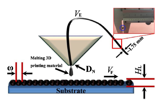
Fig. 1.
Scheme of 3D printing process with the prepared printing filament.
Table 1 Information of the samples and 3D printing parameters.
| Sample | CNTs/PLA ratio (wt%) | Melt index (g/10 min) | Fixed parameters | ||||
|---|---|---|---|---|---|---|---|
| Build orientation (deg.) | Filament diameter (mm) | Envelop temperature (°C) | Filling rate (%) | Contours number | |||
| PLA | / | ∼32.4 | 0 | 1.75 | 50 | 100 | 5 |
| CNTs/PLA-1 | 1% | ∼22.5 | |||||
| CNTs/PLA-2 | 1% | ∼22.3 | |||||
| CNTs/PLA-3 | 3% | ∼12.7 | |||||
where ω is the deposition width, DN is the nozzle diameter, VE is the extrusion velocity, VF is the filling velocity, and HL is the layer thickness, as shown in Fig. 1. It is obvious that there is linear relation between deposition width and extrusion velocity.
The diameter of prepared 3D printing filament was ca. 1.75 mm (as shown in the inset in Fig. 1), corresponding to the filament diameter of the 3D printer. To confirm appropriateness of 3D printing for the prepared CNTs/PLA composite, the MFI should be detected and adjusted due to the drastic variation of it under the function of temperature [27]. As shown in Table 1, The MFI value of PLA was ca. 32.38 g/10 min at 200 °C, while that of CNTs/PLA-1, CNTs/PLA-2, CNTs/PLA-3 was ca. 22.5 g/10 min, 22.3 g/10 min and12.7 g/10 min, respectively. The CNTs/PLA-3 sample possesses the lowest MFI with highest CNTs content among all the samples, suggesting that the addition of CNTs in PLA matrix may decrease MFI significantly. It is reported that the higher the MFI value, the harder the operation of the 3D printing process, which may lead to the decrease of the fabrication efficiency of 3D printing, performance of the printed object [28]. It indicates that the addition of CNTs should be in a small number in the overall performance, especially the thermal properties.
3.2. The morphology and microstructure analysis
As illustrated in Fig. 2, the microstructures of PLA and 3D printed matters were characterized by FE-SEM from top and side view. Fig. 2(a) shows alignment structure of PLA along the arrow direction, indicating that PLA can form an orientation microstructure via the extrusion process. This phenomenon is obvious for sample CNTs/PLA-1, as shown in Fig. 2(b). A cracked CNTs/PLA composite cross section can be observed (Fig. 2(c)), illustrating the alignment and dispersion of CNTs in PLA matrix. A single nanotube extended along the orientation of PLA surface, as depicted in the inset magnification SEM image in Fig. 2(c). It suggests that CNTs are able to be dispersed in PLA matrix by extrusion method using a twin-screw extruder. The microstructure of these two samples has demonstrated that polymer extruded may form stable orientation in micro-level.
Fig. 2.
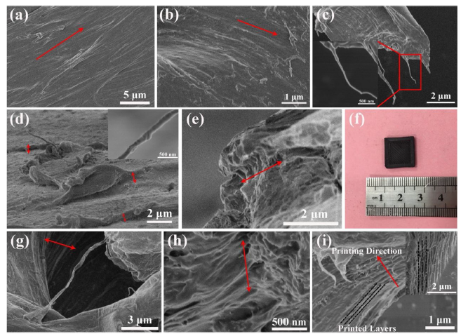
Fig. 2.
SEM micro morphology of PLA and CNTs/PLA composites before and after 3D printing. (a) the pure PLA. (b), (c) CNTs/PLA-1 with CNTs loading of 1 wt% in composite after the extrusion process, the inset image shows individual nanotube dispersed in PLA matrix. (d), (e) CNTs/PLA-1 with CNTs loading of 1 wt% in composite after 3D printing, the inset image shows individual nanotube dispersed in PLA matrix. (f) The digital photo of the 3D printed matter for sample CNTs/PLA-3. (g)-(i) CNTs/PLA-3with CNTs loading of 1 wt% in composite after 3D printing, the inset image in (i) shows the high resolution microstructure and printing layer clearly.
After 3D printing, the morphology of the samples (CNT/PLA-2 and CNT/PLA-3) is totally different compared to that of PLA and CNTs/PLA-1. As shown in Fig. 2(d) and (e), CNT/PLA-2 presents a laminated structure from top and side view. Fig. 2(d) presents three layers on the surface, demonstrating the layered fused deposition modeling (FDM) process of 3D printing. The inset high magnification SEM image illustrates the dispersion of carbon nanotube in PLA matrix. Fig. 2(e) clearly proves that the composite can also form layered structure parallel to the cross-section. To further investigate the orientation and dispersion of the CNTs in PLA matrix, the content of CNTs was increased to 3 wt% relative to PLA (sample CNTs/PLA-3), as shown in Fig. 2(f)-(i). The digital photo presents the oriented surface after 3D printing with the scale of ca. 1.5 cm × 1.5 cm. Fig. 2(g) shows the dense laminated structure and several dispersed CNTs and Fig. 2(h) presents the precipice-liked laminated structure. In addition, the laminated structure in Fig. 2(i) and the inset diagram are the most representative and regular, illustrating printed layers and printing direction clearly. A large number of extended nanotubes can also be observed along the printed layers, indicating that the CNTs dispersed well and acquire uniform orientation in PLA matrix after the 3D printing process. Thus, 3D printing method contributes to the dispersion and orientation of carbon nanotube in polymer matrix significantly. This can also be attested by TEM detection. As shown in Fig. 3 (sample CNTs/PLA-3), the CNTs/PLA composite forms worm-liked structure (Fig. 3(a) and (b)). The 3D printed composite laminated structure is distinct in Fig. 3(b). Notably, the CNTs dispersed in PLA can be observed clearly, as shown at the position of arrows in Fig. 3(b). On the basis of high resolution TEM (HR-TEM) images (Fig. 3(c) and (d)), the exact bundle size and orientation of CNTs can be determined clearly. The all CNTs distribute along one direction individually with the lattice spacing of ca. 0.34 nm, which may arise from the 3D printing orientated deposition.
Fig. 3.
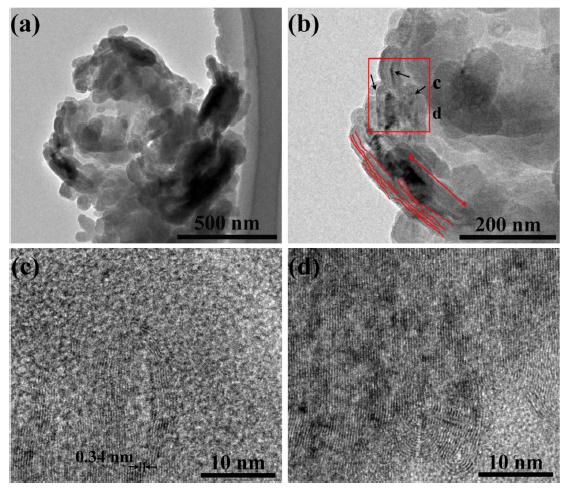
Fig. 3.
TEM photos for sample CNTs/PLA-3. (a), (b) The microstructures of the composite and CNTs dispersion in PLA matrix. (c), (d) The high-resolution TEM images showing the lattice of CNTs.
Fig. 4 illustrates Raman spectra for CNTs unique structure, PLA and CNTs/PLA composites. PLA presents a typical polymer Raman spectrum. For the CNTs/PLA composites, all of them show totally different Raman structure with PLA, presenting inverse result with the XRD diffractions. The unique D band at ∼1330 cm-1 due to disorded-induced sp3 hybridized carbon, and G-band at ∼1582 cm-1 due to first-order Raman-allowed tangential sp2 hybridized carbons [29] can be observed for all the CNTs/PLA samples, confirming the existence of CNTs in the printed matters. In addition, the secondary Raman signal of G’ mode at 2656 cm-1, which is a Raman-allowed mode for sp2 carbons and two-phonon, inter-valley, second-order Raman scattering process for carbon nanotubes [29], is strong in pristine CNTs. While this band is absence for CNTs/PLA-1 and CNTs/PLA-2 and weak for CNTs/PLA-3, this phenomenon reveals that PLA may disturb the phonon and/or electronic structure of graphene structure in dispersing CNTs [24,30]. To quantify the disorder in all the CNTs based composites, ID/IG intensity ratio between the disorded-induced D band and the Raman allowed G-band was analyzed. The intensity ration for CNTs, CNTs/PLA-1, CNTs/PLA-2, CNTs/PLA-3 are 1.37, 1.07, 1.05 and 1.18, respectively. The ID/IG decreases from 1.37 for CNTs to 1.05 for printed CNTs/PLA composite after thermal annealing. Meanwhile, the ID/IG for CNTs/PLA-2 (after 3D printing) is relatively lower than that of CNTs/PLA-1 (before 3D printing) with the same CNTs loading in the composites. This may arise from the recovery of the conjunction domain of sp2-domainated 2D grapheme crystal by removing oxygen-containing functional groups according to previous [24,31]. Furthermore, the ID/IG for CNTs/PLA-3 is higher than that of CNTs/PLA-2 with the different CNTs loading in the composites, suggesting that the content of CNTs in the composite affects the grapheme crystal significantly comparing to the thermal annealing process. The D band of sample CNTs/PLA-1 is broader than that of CNTs/PLA-2 and CNTs/PLA-3, indicating that the amorphous carbon or disorded-induced sp3 hybridized carbon may be more before 3D printing. Thus, through 3D printing, not only CNTs can form directional alignment structure in PLA matrix, but also the content of amorphous carbon or other impurities decreases.
Fig. 4.
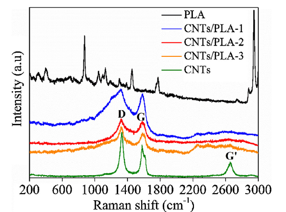
Fig. 4.
Raman spectra of pure PLA and CNTs/PLA composites before and after 3D printing.
3.3. The crystallinity and thermal behavior analysis
Although the orientated CNTs can be observed in large scale by SEM and TEM, the crystalline nature of the CNTs/PLA composites before and after 3D printing is ambiguous, as shown in XRD diffraction in Fig. 5. The diffraction peaks attributed to the (002) reflection of carbon nanotubes at 2θ = 25.96° (d002 spacing in nanotubes of 0.34-0.35 nm for the graphite crystal, shown in Fig. 5) can be clearly seen for the pristine CNTs, which is identified as the hexagonal graphite structure [2]. The other representative peaks of CNTs, such as (100), (004) and (103), appeared at 2θ = 43.2°, 53.7°, 62.8°, respectively. However, these representative CNTs diffraction peaks disappear for all the CNTs/PLA composites, indicating that CNTs disperse less on the surface of CNTs/PLA composites. The pure PLA shows a broad diffraction peak at 2θ = 16° along with a small hump at 2θ = 32.3°, revealing the amorphous nature [32]. The prepared CNTs/PLA composites present mainly the diffractions of PLA in Fig. 5. Notably, the CNTs/PLA-3 loading of 3 wt% of pristine CNTs in the composite results in a sharp intense peak at 16.2° at the central of the broad peak, attributing to the 200 and 110 reflections of the PLA α crystals in the printed matter [16]. A weak crystalline peak can also be seen on the CNTs/PLA-1 curve at ca. 16.2°. These results may arise from the surface grafted PLA polymer, which acts as the nucleating site for the growth of PLA crystals on the carbon nanotubes surface [32]. While this peak is absence in sample CNTs/PLA-2 with nanotubes loading of 1 wt%, suggesting that the crystal of PLA on the nanotubes surface is affected by the CNTs loading in CNTs/PLA composite after 3D printing. According to the XRD results, it is quite evident that the content of CNTs loading in CNTs/PLA composites slightly influences the crystalline behavior. These results can be further attested by the differential scanning calorimetric (DSC) characterization of PLA and CNTs/PLA composites.
Fig. 5.

Fig. 5.
XRD spectra of pure PLA and CNTs/PLA composites before and after 3D printing.
Fig. 6 shows the typical DSC thermograms of PLA and CNTs/PLA composites under the treatment of extrusion and 3D printing. Glass transition temperature (Tg), crystallization temperature (Tc), melting temperature (Tm), crystallization enthalpy (△Hc), and melting enthalpy (△Hm) of PLA and CNTs/PLA composites were determined from the heating cycles, as annotated in Fig. 6 and summarized in Table 2. According to the previous [16,33], the degree of crystallinity (Xc) of the PLA based composites can be calculated from Eq. (2) as follows:
Fig. 6.
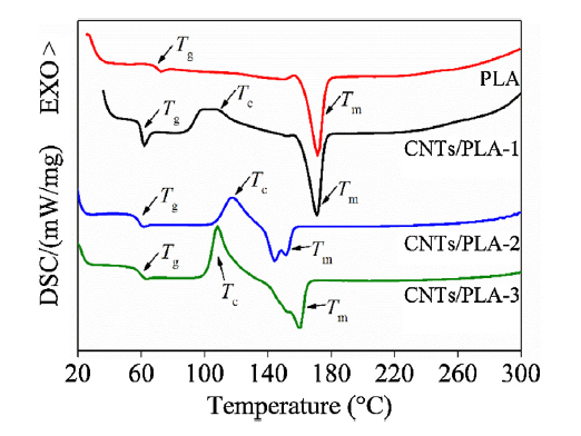
Fig. 6.
DSC curves of pure PLA and CNTs/PLA composites before and after 3D printing.
Table 2 Summary of DSC heating curves of PLA and CNTs/PLA composites before and after 3D printing.
| Samples | Heating process | ||||||||||
|---|---|---|---|---|---|---|---|---|---|---|---|
| aTg (°C) | bTc (°C) | cΔHc (J/g) | Tm (°C) | dΔHm (J/g) | Xc (%) | ||||||
| T1 | T2 | T3 | T4 | ΔCp (J g-1 K-1) | Tc1 | Tc2 | |||||
| PLA | 67.5 | 69.1 | 70.7 | 70.9 | 0.308 | / | / | / | 171.5 | 34.4 | / |
| CNTs/PLA-1 | 58.8 | 59.7 | 60.4 | 60.5 | 0.912 | 89.8 | 119.2 | 40.79 | 171.0 | 38.27 | 2.7 |
| CNTs/PLA-2 | 55.7 | 58.1 | 58.4 | 60.2 | 0.572 | 107.4 | 126.7 | 23.31 | 144.3 | 21.8 | 1.6 |
| CNTs/PLA-3 | 56.7 | 59.7 | 60.0 | 62.0 | 0.564 | 101.9 | 115.3 | 37.68 | 159.9 | 34.35 | 3.7 |
aTg is the glass transition temperature of the samples, and T1-T4 are the Onset, Midpoint, Inflect. Pt. and Endset temperature of Tg.
bTc is the crystallization temperature, and Tc1 and Tc2 are the Onset and Endset of Tc. Tm is melting point.
c,dΔH are the enthalpy changes of the crystallization and melting point respectively and calculated by the area of the peaks.
where the △H=△Hm-△Hcc in the heating cycle, and △Hcc is the cold crystallization enthalpy. △H°m is the melting enthalpy of 100 % crystalline polymer, which was taken to be 93.6 J/g for PLA [34]. △Hcc was replaced by △Hc in this research. The calculated Xc values are listed in Table 2. It is obvious that the Xc for CNTs/PLA-3 is the largest and that for CNTs/PLA-2 is the lowest. Owing to the amorphous structure of PLA, the crystalline behavior and Tc are absence. These results are in accordance with the results of XRD diffraction in which CNTs/PLA-3 shows obvious crystalline peakand CNTs/PLA-1 presents weak crystalline peak at ca. 16.2°. But CNTs/PLA-2 shows mainly amorphous diffraction peaks. The degree of crystallinity of CNTs/PLA composites demonstrated that the addition of CNTs could supply nucleating site for the growth of PLA crystals. The 3D printing process may disturb this kind of crystals growth behavior since the process can decrease the defect on the surface of CNTs according to the Raman results. Thus, the presence of defects on CNTs surface may contribute to the crystallinity of PLA in CNTs/PLA composites. As shown in Table 2, the Tg values of all the CNTs/PLA samples are quite similar, while quite different from that of PLA. It implies that the extrusion and 3D printing process may have no impact on Tg. The PLA Tg is almost 10 °C higher than that of the CNTs/PLA composites, indicating that the addition of CNTs affects Tg largely due to the molecular interactions between PLA and CNTs. The heat capacity change (ΔCp) at the Tg in PLA and the composites is a function of both the relative amount of the participating amorphous phase and the difference of conformational entropy between the glassy and rubbery state. Therefore, it is proportional to the quantity of amorphous in specimen [35]. The ΔCp value of CNTs/PLA-1 is the largest of 0.912 J g-1 K-1 while that of CNTs/PLA-3 is the lowest of 0.564 J g-1 K-1, suggesting that CNTs/PLA-1 and CNTs/PLA-3 own the largest and smallest amorphous domain respectively in CNTs/PLA composites. These results imply that the addition of CNTs and 3D printing process may decrease the amorphous domain in CNTs/PLA composites. Moreover, the crystallization (Tc, ΔHc) behavior of CNTs/PLA-2 further indicates that the degree of crystallinity is the lowest among the CNTs/PLA composites. By comparing the melting (Tm, ΔHm) behavior of all the samples, it is obvious that the pure PLA is most stable in melting process and CNTs/PLA-2 goes to the opposite extreme. The melting difference between CNTs/PLA-1 and CNTs/PLA-2 attests that the composite may become unstable after 3D printing treatment. Notably, the CNTs/PLA-3 melting temperature is higher than that of CNTs/PLA-2, indicating that the increase of CNTs loading in the composite contributes to the melting stability [36,37].
The thermal stability of printed CNTs/PLA composites is confirmed by thermal gravity analysis, as depicted in Fig. 7. According to the DTG curves in Fig. 7(b), all the samples have only one decomposition stage, suggesting that only PLA decomposed. The decomposition temperatures and residual weight of the samples are shown in Table 3. Fig. 7(a) illustrates the variation trend of the decomposition onset temperature along the arrow. The onset decomposition temperature decreases from 285 °C for pure PLA to 255 °C for printed CNTs/PLA-3 after thermal annealing. On the basis of Tonset of all the samples, pure PLA possesses the best thermal stability while that of CNTs/PLA-3 is the lowest. These results reveal that PLA decomposition temperature would decrease largely after 3D printing. Meanwhile, the addition and orientation of CNTs in PLA matrix may not contribute to thermal stability of CNTs/PLA composite comparing sample CNTs/PLA-2 with CNTs/PLA-3. The end decomposition temperatures of all samples are almost the same in Table 3. The residual weight of PLA is 0, suggesting that PLA is able to decompose totally under the function of temperature. The other CNTs based composites have the proper residual weights, which correspond to the CNTs loading in PLA approximately. The total residual weights at 690 °C are 1.3 wt % (CNTs/PLA-1) and 1% (CNTs/PLA-2), arising from the efficient removal of oxygen-containing functional groups or amorphous carbon during 3D printing process, corresponding to the Raman results.
Table 3 Main decomposition and residual weight of the prepared samples.
| Sample | T1onset (°C) | T2end (°C) | Residual weight (wt%) |
|---|---|---|---|
| PLA | 285 | 374 | 0 |
| CNTs/PLA-1 | 284 | 372 | 1.3 |
| CNTs/PLA-2 | 262 | 371 | 1 |
| CNTs/PLA-3 | 255 | 370 | 2 |
1,2Are the temperatures of onset and end in DTG curves for the decomposition.
Fig. 7.

Fig. 7.
TGA thermograms of the of pure PLA and CNTs/PLA composites before and after 3D printing. (a) TG curves; (b) DTG curves.
Fig. 8 shows the surface resistance of CNTs/PLA composites before and after 3D printing. It is known that the PLA is insulative as a polymer. When carbon nanotubes were added into the matrix, the electricity of the CNTs/PLA composites is various. As shown in Fig. 8, with the addition of 1 wt% CNTs, the surface resistivity is ca. 1 × 10¹² Ω/m2. After the 3D printing process, the surface resistivity decreases to 1 × 10⁸ Ω/m2 significantly. This result indicates that 3D printing process is beneficial to increasing the electrical conductivity of CNTs/PLA composite. This may be due to the orientation and relatively homogenous dispersion of CNTs in PLA matrix after 3D printing, as stated in TEM and SEM analysis. When the CNTs content increase to 3 wt % in the composite, the surface resistivity decreases to the magnitudes of ca. 105 Ω/m2. It suggests that increasing CNTs content in PLA benefits to the formation of percolating conductive paths in polymer matrix, and assists in the dissipation of electric charge over the surface of the material because of the excellent electrical conductivity of CNTs [38]. The avometer detection reveals that the resistance of 3D printed matter (ca. 0.718 MΩ) is close to human body (ca. 0.736 MΩ), which may hold the potential application in electrical devices and industries [22].
Fig. 8.

Fig. 8.
Surface resistivity of the prepared CNTs/PLA composites before and after printed. The inset photos show the resistance of the 3D printed matter and human body detected by avometer.
3.4. The mechanical properties analysis
Fig. 9 depicts the mechanical properties of the PLA and CNTs/PLA composites. The average tensile strength obtained by using the tensile strength values of four measured samples is shown in Fig. 9(a). It is obvious that the tensile strength of PLA is ca. 35.2 MPa, while that of the CNTs/PLA composites are higher. This suggests that the addition of CNTs contributes to the tensile strength of PLA. Comparing CNTs/PLA-1 and CNTs/PLA-2, the tensile strength of CNTs/PLA-2 is higher, indicating that the 3D printing process is beneficial to the tensile strength for CNTs/PLA composite. This may arise from the orientation of CNTs in PLA matrix after the 3D printing process [39]. The average surface roughness is shown in Fig. 9(b). The Ra value of PLA is the lowest while that of CNTs/PLA-3 is the highest. Meanwhile, the Ra value presents an increasing trend with the increase in content of CNTs. The results suggest that the addition of CNTs enhances the surface roughness significantly. Comparing CNTs/PLA-1 and CNTs/PLA-2, the surface roughness of CNTs/PLA-2 is higher, indicating that the 3D printing process is also beneficial to the surface roughness for CNTs/PLA composite. We suggest that the addition of CNTs and 3D printing process are both contribute to the tensile strength and surface roughness completely [[40], [41], [42]].
Fig. 9.
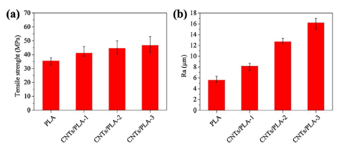
Fig. 9.
The mechanical properties of PLA and CNTs/PLA composites: (a) tensile strength, (b) surface roughness.
4. Conclusion
In summary, the CNTs/PLA composites were prepared via the simple process in combination of extrusion and 3D printing processes. The CNTs has been largely aligned in PLA matrix observed in SEM and TEM. Raman results indicate that 3D printing process is helpful to remove the impurities, oxygen-containing functional groups or amorphous carbon with thermal annealing. The increasing content of CNTs loading in CNTs/PLA composites enhances the degree of crystallinity slightly due to the presence of defects on CNTs surface. These defects may supply nucleating site for the growth of PLA crystals. The addition of CNTs in PLA matrix may has beneficial effect on the melting stability, tensile strength and surface roughness of the composite, as well as the 3D printing process. Moreover, the existence of CNTs contributes to the electrical conductivity of CNTs/PLA composite, showing a surface resistivity of ca. 105 Ω/m2 with the CNTs loading of 3 wt% in the composite and a similar resistance with human body via the avometer testing. According to the results, we assume that the composite with well-ordered CNTs fillers prepared via the simple process may be used as thermal resistance plastic in printing industry, such as printing roller. The future work may be focused on the further increasing of thermal stability for the composite.
Acknowledgements
This work was financially supported by the National Natural Science Foundation of China (Nos. 51802259 and 51772243), the China Postdoctoral Science Foundation Funded Project (No. 2019M663785), the Natural Science Foundation of Shaanxi (No. 2019JQ-510), Xi’an and Xi’an Beilin District Programs for Science and Technology Plan (Nos. 201805037YD15CG21(18) and GX1913), the Promotion Program for Youth of Shaanxi University Science and Technology Association (No. 20190415), and the Fund of Key laboratory of Processing and Quality Evaluation Technology of Green Plastics of China National Light Industry Council (No. PQETGP2019003).
Reference
DOI
URL
PMID
[Cited within: 1]

Integrating carbon nanotubes (CNTs) with biological systems to form hybrid functional assemblies is an innovative research area with great promise for medical, nanotechnology, and materials science applications. The specifics of molecular recognition and catalytic activity of proteins combined with the mechanical and electronic properties of CNTs provides opportunities for physicists, chemists, biologists, and materials scientists to understand and develop new nanomachines, sensors, or any of a number of other molecular assemblies. Researchers know relatively little about the structure, function, and spatial orientation of proteins noncovalently adsorbed on CNTs, yet because the interaction of CNTs with proteins depends strongly on the tridimensional structure of the proteins, many of these questions can be answered in simple terms. In this Account, we describe recent research investigating the properties of CNT/protein hybrids. Proteins act to solvate CNTs and may sort them according to diameter or chirality. In turn, CNTs can support and immobilize enzymes, creating functional materials. Additional applications include proteins that assemble ordered hierarchical objects containing CNTs, and CNTs that act as protein carriers for vaccines, for example. Protein/CNT hybrids can form bioscaffolds and can serve as therapeutic and imaging materials. Proteins can detect CNTs or coat them to make them biocompatible. One of the more challenging applications for protein/CNT hybrids is to make CNT substrates for cell growth and neural interfacing applications. The challenge arises from the structures' interactions with living cells, which poses questions surrounding the (nano)toxicology of CNTs and whether and how CNTs can detect biological processes or sense them as they occur. The surface chemistry of CNTs and proteins, including interactions such as pi-pi stacking interactions, hydrophobic interactions, surfactant-like interactions, and charge-pi interactions, governs the wealth of structures, processes, and functions that appear when such different types of molecules interact. Each residue stars in one of two main roles, and understanding which residues are best suited for which type of interaction can lead to the design of new hybrids. Nonlocally, the peptide or protein primary, secondary, and tertiary structures govern the binding of proteins by CNTs. The conjugation of proteins with CNTs presents some serious difficulties both experimentally and culturally (such as bridging the
DOI
URL
PMID
[Cited within: 1]
Worldwide commercial interest in carbon nanotubes (CNTs) is reflected in a production capacity that presently exceeds several thousand tons per year. Currently, bulk CNT powders are incorporated in diverse commercial products ranging from rechargeable batteries, automotive parts, and sporting goods to boat hulls and water filters. Advances in CNT synthesis, purification, and chemical modification are enabling integration of CNTs in thin-film electronics and large-area coatings. Although not yet providing compelling mechanical strength or electrical or thermal conductivities for many applications, CNT yarns and sheets already have promising performance for applications including supercapacitors, actuators, and lightweight electromagnetic shields.
DOI
URL
PMID
[Cited within: 1]
Additive manufacturing, otherwise known as three-dimensional (3D) printing, is driving major innovations in many areas, such as engineering, manufacturing, art, education and medicine. Recent advances have enabled 3D printing of biocompatible materials, cells and supporting components into complex 3D functional living tissues. 3D bioprinting is being applied to regenerative medicine to address the need for tissues and organs suitable for transplantation. Compared with non-biological printing, 3D bioprinting involves additional complexities, such as the choice of materials, cell types, growth and differentiation factors, and technical challenges related to the sensitivities of living cells and the construction of tissues. Addressing these complexities requires the integration of technologies from the fields of engineering, biomaterials science, cell biology, physics and medicine. 3D bioprinting has already been used for the generation and transplantation of several tissues, including multilayered skin, bone, vascular grafts, tracheal splints, heart tissue and cartilaginous structures. Other applications include developing high-throughput 3D-bioprinted tissue models for research, drug discovery and toxicology.
DOI
URL
PMID
[Cited within: 4]
DOI
URL
PMID
[Cited within: 2]
The utilization of 3D printing of highly conductive (sigma approximately 2350 S m(-1) ) polymer composite structures for the functional optimization of scaffold-shaped liquid sensors is demonstrated. This study can open the pathway of the application of 3D printing of conductive composites for optimization of structures useful for various applications such as smart sensors in textile or in the field of electronics.
DOI
URL
PMID
[Cited within: 1]
Isolated graphene, a nanometer-thick two-dimensional analog of fullerenes and carbon nanotubes, has recently sparked great excitement in the scientific community given its excellent mechanical and electronic properties. Particularly attractive is the availability of bulk quantities of graphene as both colloidal dispersions and powders, which enables the facile fabrication of many carbon-based materials. The fact that such large amounts of graphene are most easily produced via the reduction of graphene oxide--oxygenated graphene sheets covered with epoxy, hydroxyl, and carboxyl groups--offers tremendous opportunities for access to functionalized graphene-based materials. Both graphene oxide and graphene can be processed into a wide variety of novel materials with distinctly different morphological features, where the carbonaceous nanosheets can serve as either the sole component, as in papers and thin films, or as fillers in polymer and/or inorganic nanocomposites. This Review summarizes techniques for preparing such advanced materials via stable graphene oxide, highly reduced graphene oxide, and graphene dispersions in aqueous and organic media. The excellent mechanical and electronic properties of the resulting materials are highlighted with a forward outlook on their applications.
UNSP 107712

 WeChat


