

1. Introduction
It is well known that SiO2f/SiO2 composite is an advanced ceramic-based composite with good thermal-shock resistance, high ductility, high reliability and low crack-insensitivity [1,2]. So it is an ideal material for fabricating antenna radome [3,4]. Besides, SiO2f/SiO2 composite is also attractive as high-temperature structural material, thermal protective material, and etc. However, for some actual applications the SiO2f/SiO2 composite needs to be joined to itself or to metals. Compared with mechanical joining and adhesive joining, active brazing method has a potential to satisfy the connection requirement of complex components with some advantages such as decreasing structure weight and elevating service temperature of the joints [5,6]. Recently, a few studies have been reported on the joining of SiO2 ceramic composite [[7], [8], [9], [10]].
However, there exist two great difficulties when joining SiO2f/SiO2 composite to metals. Firstly, the coefficient of thermal expansion (CTE) of the SiO2f/SiO2 composite is extremely low, only 0.33 × 10⁻⁶ K-1, while that for most metals is not lower than 4.6 × 10⁻⁶ K-1, for example, the CTE of Nb is 7.31 × 10⁻⁶ K-1 [11] whereas for those stainless steels or alloying steels it is even high up to 11.4 × 10⁻⁶-16.6 × 10⁻⁶ K-1. The great difference in CTE between the SiO2f/SiO2 composite and the joined metal would lead to large residual thermal stresses within the dissimilar joints, and thus easily cause direct cracking when joining large-size component [12]. Therefore, for decreasing the thermal residual stresses, effective measures such as adding a buffer layer [13,14], using composite brazing filler [9,15,16] or building gradient structure in the surface layer of joined ceramic [7,10,17], must be taken when joining such kind of dissimilar materials.
Secondly, the wettability of traditional brazing alloys on SiO2f/SiO2 composite is a problem. Therefore, active brazing method can be applied for SiO2f/SiO2 composite joining. AgCu-Ti brazing alloy is commonly used for ceramic joining, in which Ti is used as active element. Some researchers have used the AgCu-Ti brazing alloy to join SiO2 ceramic [[7], [8], [9], [10]], but the corresponding brazing temperature is high up to 1123-1153 K. It is believed that decreasing the brazing temperature should be beneficial to relieving residual thermal stresses within the dissimilar joint.
Concerning the previous CTE mismatch problem, according to several references [[18], [19], [20]], building a gradient structure at the surface of the joined ceramic was effective on releasing the residual thermal stresses within the joint. An attempt was made by cutting narrow grooves at intervals in the surface layer of the joined SiO2f/SiO2 composite to build the needed gradient structure, and such a gradient structure could play an important role in releasing the residual thermal stresses within the dissimilar joints [10]. During the brazing process the molten brazing alloy would melt and infiltrate into the grooves, and thus a ceramic-metal mixture structure would be formed in the surface layer of the SiO2f/SiO2 ceramic. This means that through this composite layer the CTE difference between the SiO2f/SiO2 composite and the joined metal could be decreased effectively. Therefore, the peak value of the residual stresses within the dissimilar joints caused by the CTE difference can be decreased significantly.
Additionally, it was reported that, by the addition of low-melting-point element In for decreasing the liquidus temperature of the brazing alloy, the Ag-Cu-In-Ti system brazing alloys had been successfully developed for joining some ceramics such as Al2O3, SiC, AlN, Si3N4 [[21], [22], [23]], etc, in which typical compositions included Ag-23.5Cu-14.5In-1.25Ti and Ag-19.5Cu-5In-3.0Ti [24], and the corresponding brazing temperature were between 1033 and 1223 K. According to the authors’ previous experimental results, it was difficult to join SiO2f/SiO2 composite to Nb metal by directly using the above two Ag-Cu-In-Ti brazing fillers. To our understanding the main reason for this fact should be the insufficient Ti amount and the resulted poor wettability on the composite.
In the present study, three compositions of Ag-Cu-In-Ti system alloys were newly designed for the joining SiO2f/SiO2 composite to Nb metal. And this study was intended to solve the questions of what reactions would occur at the interface between the joined materials and the new Ag-Cu-In-Ti fillers and, whether the newly-developed brazing alloy could offer a stable SiO2f/SiO2-Nb joint.
2. Experimental procedures
Three compositions of Ag-Cu-In-Ti brazing alloys were newly designed. For 1# and 2# alloys the Ti concentration is at the same level of 5 wt%, but the content of element In in 2# alloy is higher than that in 1# alloy (Table 1). Concerning 3# alloy, the In concentration is identical to that in 1# alloy but its Ti content is lower than 1# and 2# alloys. It should be noticed that the ratio of Ag to Cu in the three kinds of filler alloys was fixed at the Ag-28Cu (wt%) eutectic point.
Table 1 Composition and melting temperature of the three Ag-Cu-In-Ti alloys.
| Alloy code | Composition (wt%) | TS (K) | TL (K) | |||
|---|---|---|---|---|---|---|
| Ag | Cu | In | Ti | |||
| 1# | 61.2 | 23.8 | 10 | 5 | 921.8 | 1011.9 |
| 2# | 57.6 | 22.4 | 15 | 5 | 913.5 | 1014.0 |
| 3# | 61.9 | 24.1 | 10 | 4 | 932.7 | 1012.4 |
In Ag-Cu-In ternary alloy system, the addition of element In could decrease the melting point significantly, as shown in Fig. 1. Whereas, excessive In content would inevitably cause great brittleness of the filler alloy. Therefore, in this study the maximum In content appeared in 2# filler alloy. As is known, the addition of Ti into the filler alloy can improve the wettability on the ceramic composite. So far, some of the commercial Ti-containing filler alloys have been developed, such as Incusil-ABA, Cusin-1-ABA, Cusil-ABA, as well as Ticusil [25,26].
Fig. 1.
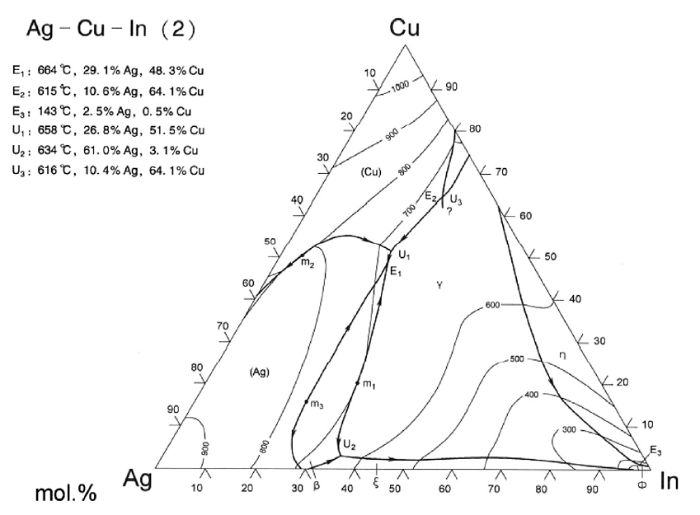
Fig. 1.
Ag-Cu-In ternary phase diagram [27].
As described previously, 1.25%-3.0% Ti amount in Ag-Cu-In-Ti system filler alloy is not sufficient to realize ideal joining of SiO2f/SiO2 composite to Nb metal. As a consequence the Ti content was increased to 4.0% or 5.0% in the three newly designed filler alloys.
The wettability of the three brazing alloys on SiO2f/SiO2 composite was studied with the sessile drop method under the heating condition of 1073 K/30 min in a vacuum furnace. The brazing alloy sample with a diameter of about 5 mm and a weight of about 200 mg was placed on a SiO2f/SiO2 composite with a size of 10 mm × 10 mm × 3 mm. The static contact angles of the three brazing alloys on the composites were measured from the wetting interface after the specimens cooled with the vacuum furnace by an optical microscope (JQC(15 J)), and then the average values of the contact angles were calculated from four vertical directions of the specimens. For further observing the wetting behavior, dynamic wettability of 1# alloy on the SiO2f/SiO2 composite was studied as the follows: The chamber of the furnace was first evacuated to 1.5 × 10⁻³ Pa by a mechanical rotatory pump and molecule pump at room temperature. Then, the vacuum system was turned off, and high-purity (99.999%) argon was put into the chamber with a pressure of 0.1 MPa. Subsequently the chamber was evacuated to 1.5 × 10⁻³ Pa again, the vacuum system was turned off, and argon was put into the chamber for the second time. The samples were heated to 1073 K from ambient temperature at a heating rate of 10 K/min, and then were held at the temperature for 40 min. During the heating process, the morphologies of the molten droplet by taking sideways photos every two seconds. While the morphologies were recorded dynamically every two minutes at the holding temperature of 1073 K to reflect the change of the contact angle with the holding time. Thus the contact angles of the brazing alloys on the composite were calculated from these droplet images using a computer method based on the Laplace equations. The accuracy of the contact angle measurements should be within ±1°.
The filler alloys were fabricated into brazing foils with a thickness about 50 μm by rapid solidification technique, as shown in Fig. 2. Besides, SiO2f/SiO2 composite pieces with about 15 vol.% porosity were joined to Nb metal using the three Ag-Cu-In-Ti brazing foils, respectively. SiO2f/SiO2 specimens with a dimension of 15 mm × 8 mm × 6 mm and Nb specimens with a dimension of 10 mm × 8 mm × 3 mm were prepared to form a lap joint with a brazing area of 8 mm × 5 mm. Prior to brazing experiment a narrow groove with a width of 0.4-1.0 mm and a depth of 1.0-2.0 mm was machined at the surface of the joined SiO2f/SiO2 composite, as shown in Fig. 3. The area from the top of groove to the bottom along the depth direction can be regarded as a kind of composite structure so that the residual stress gradient should be decreased because the coefficient of thermal expansion of this composite structure falls in between the composite and the three kinds of metals. In previous report [10], the effect of groove was verified when brazed with Ag-Cu-Ti filler alloy. Then in this study when the filler alloy was changed to Ag-Cu-In-Ti, the groove on the joining surface should play the same role in decreasing the residual thermal stress.
Fig. 2.
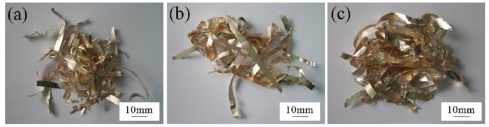
Fig. 2.
Morphologies of brazing foils fabricated by rapid solidification technique: (a) 1# alloy; (b) 2# alloy; (c) 3# alloy.
Fig. 3.
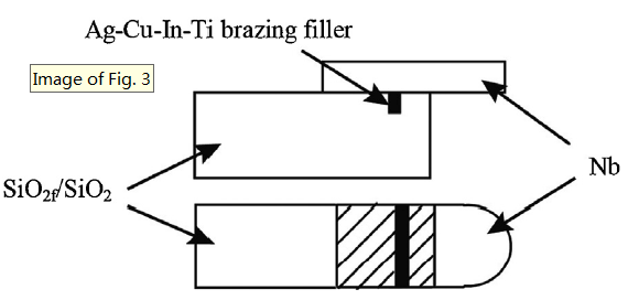
Fig. 3.
Lap joint diagram of SiO2f/SiO2 composite to Nb metal.
All the filler foils and the samples to be joined were ultrasonically cleaned in acetone and dried by air blowing. Double-layer of Ag-Cu-In-Ti filler foils were preset between the joined materials, and the assembled specimens were put into a vacuum furnace. The furnace chamber was evacuated to 2.5 × 10⁻³ Pa at room temperature, and then the specimens were heated to brazing temperature at a heating rate of 8-10 K/min. The brazing temperature was fixed at 1073 K and three dwell times of 10 min, 30 min and 60 min were chosen for all of the three brazing alloys. Within the holding time at the brazing temperature of 1073 K the vacuum was kept between 5.0 × 10⁻³ -8.2 × 10⁻³ Pa. Afterwards the joint specimens were cooled to room temperature with the vacuum furnace.
At least three specimens were tested for each brazing condition, and in particular, for the joints brazed with the three filler alloys at the three brazing temperatures for 10 min, five specimens were conducted. Shear strength test for the brazed joints was conducted at room temperature. The joint strength is given in the form of error bars, in which the value of the upper line is the maximum strength among the three specimens, the value of lower line corresponds to the minimum strength, and middle one represents the average strength.
Both the cross-sectional microstructure of the joints and semi-quantitative composition analysis were examined by a scanning electron microscope (SEM, FEI nano 450) equipped with an X-ray energy-dispersive spectrometer (EDS, INCA-E350). The sample used in this analysis was coated with a thin layer of gold, and thus 0.31-0.95 at.% Au was also detected in those microzones. The listed data of the EDS analysis in this paper are the normalized results without removing the element Au. For determination of the phases formed in the joints, an X-ray diffraction (XRD, D8 ADVANCE) analysis was performed on the surface of a fractured specimen. Furthermore, the thicknesses of reaction layers close to the SiO2f/SiO2 composite within the dissimilar joints were measured under the SEM. For each sample the thicknesses of the reaction layer at different locations were measured through the SEM, and the presented data corresponded to their average value.
3. Results and discussion
3.1. Wettability of Ag-Cu-In-Ti brazing alloys on SiO2f/SiO2 composite
The solidus and liquidus temperatures measured by the different thermal analysis (DTA) method are listed in Table 1. It appears that, from the comparison of 1# alloy with 2# alloy, the increase of In content in the Ag-Cu-In-Ti filler alloy only decreases the solidus temperature but it has no evident influence on the liquidus temperature. The results of the wetting experiment in the vacuum furnace showed that the contact angles of 1#, 2# and 3# filler alloys were 74°, 83° and 86°, respectively, as shown in Fig. 4. This means that the wettability of 1# filler alloy is a little better than 2# or 3# filler alloy. For the Ag-based filler alloy with Ti-containing, the wettability was dependent on the interfacial reaction between the filler alloy and the brazed ceramics. After the reaction, element Ti would be consumed to some extent, and then the spreading of the filler alloy would be difficult. As a result, the contact angle was generally large. For the commercial Ag-Cu-Ti filler alloy (Ticusil), its wettability was investigated in our previous work, and the equilibrium contact angle at 1153 K was 75°. It can be seen that the wettability of the commercial Ag-Cu-Ti filler alloy was same to the newly-designed Ag-Cu-In-Ti filler alloy.
Fig. 4.
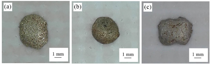
Fig. 4.
Wetting morphologies of three brazing alloy samples on SiO2f/SiO2 composite (heating condition: 1073 K /30 min): (a) 1# alloy; (b) 2# alloy; (c) 3# alloy.
The results of dynamic wettability for 1# brazing alloy are presented in Fig. 5. After 1# alloy melted it showed a high contact angle of 138° on the SiO2f/SiO2 composite. With the increase of the temperature its contact angle gradually became smaller. When the temperature reached 1073 K it decreased to 97°, indicating still non-wetting with the ceramic composite (Fig. 5(a)).
Fig. 5.
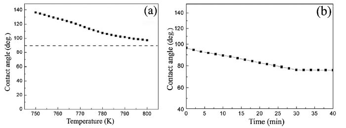
Fig. 5.
Wetting kinetics of 1# alloy on SiO2f/SiO2 composite: (a) change of contact angle with temperature; (b) change of contact angle with holding time at 1073 K.
Theoretically, when the temperature increases, the wettability of the filler alloy on the SiO2f/SiO2 composite would be improved. But the main objective of this study is to lower the brazing temperature and to decrease the residual stress within the joint. The change of the contact angle with the holding time at 1073 K is shown in Fig. 5(b). With the prolonging of the holding time at 1073 K, the contact angle kept on decreasing. After being held at this temperature for about 6 min the alloy sample started to wet the SiO2f/SiO2 composite and for the holding time of 30 min the contact angel reached an equilibrium value of 76°. Fig. 6 shows the morphologies of 1# alloy molten droplet on the SiO2f/SiO2 composite at different heating stages.
Fig. 6.
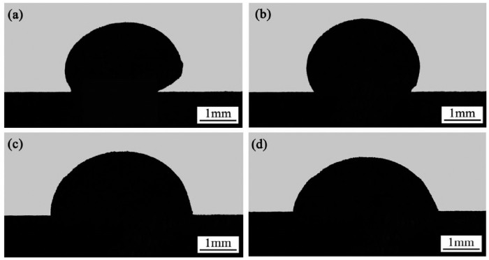
Fig. 6.
Morphologies of 1# molten droplet on SiO2f/SiO2 composite at different heating stages: (a) heated to 1053 K; (b) heated to 1073 K; (c) at 1073 K for 10 min; (d) at 1073 K for 30 min.
3.2. Interfacial reactions within SiO2f/SiO2-Nb joints brazed at 1073 K for 10 min
It is evident that for the joints brazed with the three filler alloys, a grayish reaction band with a thickness of 2-3 μm is visible at the interface between SiO2f/SiO2 composite and the brazing filler metal (Fig. 7). At the Nb side, sound metallurgical bonding has also been achieved. It is also observable that no brazing alloy infiltrated into the pores of the SiO2f/SiO2 substrate.
Fig. 7.
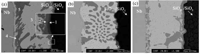
Fig. 7.
Microstructures of SiO2f/SiO2-Nb joint brazed with three Ag-Cu-In-Ti alloys (1073 K/10 min): (a) 1# alloy; (b) 2# alloy; (c) 3# alloy.
The EDS analyzed results (Table 2) of the SiO2f/SiO2-1# filler-Nb joint indicated that Ti and O were enriched in the diffusion reaction layers close to the composite (“1” and “2” in Fig. 7(a)). Considering that 7.37 at.% or 16.52 at.% Si is contained in layer “1” or “2”, respectively, it should be reasonable to assume that there should exist SiO2 phase in the two layers. It is strange to notice that the concentration of element Cu in layer “1” is rather high, 27.03 at.%. It is also noticeable that the active element Ti not only segregated in the microzones “1” and “2”, but also distributed in the gray diffusion layer (microzones “4” and “5” in Fig. 7(a)). In addition, at the central part of the joint, Ag-based solid solution was the main phase formed in the white zone “3”, with low amounts of Cu, O and In.
Table 2
EDS analyzed results of micro-zones marked in
| Micro-zone | Composition (at%) | Possible phase | |||||||
|---|---|---|---|---|---|---|---|---|---|
| Ag | Cu | Ti | In | Nb | Si | O | Au | ||
| 1 | 0.60 | 27.03 | 39.73 | 0.10 | 0.07 | 7.37 | 24.54 | 0.56 | Cu-Ti-O and SiO2 |
| 2 | 0.33 | 4.26 | 28.13 | 0.03 | 0.05 | 16.52 | 50.37 | 0.31 | Ti-O, Ti-Si and SiO2 |
| 3 | 81.81 | 7.34 | 0.06 | 3.54 | 0.05 | 0.09 | 6.52 | 0.59 | Ag(s, s) |
| 4 | 1.05 | 74.03 | 21.27 | - | - | 0.02 | 2.68 | 0.95 | Cu-Ti compound |
| 5 | 1.17 | 51.77 | 40.81 | - | 0.98 | 0.02 | 4.44 | 0.81 | Cu-Ti compound |
Fig. 8 presents the corresponding element area distribution maps for the brazed joint in Fig. 7(a). The grayish reaction layer with a thickness of 2-3 μm in Fig. 7(a) is composed of layers “1” and “2”. It is noticeable that Cu, Ti, and O (Fig. 8(b), (c), (g) and Table 2) have segregated together within layer “1” and probably formed Ti-Cu-O compound, whereas in layer “2” it has been enriched with element Ti, Si and O (Fig. 8(c), (f), (g) and Table 2), indicating the presence of Ti-O, Ti-Si and SiO2 there.
Fig. 8.
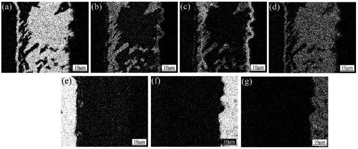
Fig. 8.
Area distribution maps of elements Ag (a), Cu (b), Ti (c), In (d), Nb (e), Si (f) and O (g) for the joint in
It is clear in Fig. 8 that the area distribution of In is in good agreement with that of Ag (Fig. 8(a) and (d)). In the meantime, according to the EDS analysis for the microzone “3” as shown in Table 2, the element In almost existed in the form of Ag(In) solid solution. As a consequence, the addition of In as an melting-point depressant was suitable for Ag-Cu-Ti system filler alloy, and it appeared that the In addition didn’t weaken the activity of element Ti in the filler alloy.
However, the interaction of Cu with Ti can be deduced from the elemental distribution maps (Fig. 8(b) and (c)). The combination of Cu with Ti and would impair the Ti activity to some extent. For SiO2f/SiO2 composite, which is difficult to be wetted by common filler alloy, the higher content of Ti in the filler alloys is necessary.
During the brazing processing the active element Ti diffused strongly to the surface of SiO2f/SiO2 composite and reacted with SiO2. A simple way to analyze the Ti/SiO2 reaction system is by conventional thermodynamics whereby chemical reaction is energetically possible whenever the molar Gibbs energy ΔG0 of the reaction is negative. The reactions of element Ti with SiO2 and the corresponding ΔG0 values can be expressed by the following formulae [28]:
According to the calculated results, at the brazing temperature of 1073 K theΔG0 value of reaction (1) is -103.1 kJ/mol. The negativeΔG0 values signify that the reaction can occur spontaneously during the brazing process [[29], [30], [31]]. Furthermore, elements Cu and Ti in the brazing alloy would further react with the TiO released from reaction (1) by the following formula:
Voytovych et al. [32] demonstrated that the reaction layers of metal-like M6X-type Ti3Cu3O and Ti4Cu2O compounds were formed at the interface by the reaction between the Ti-containing alloy and alumina. In the present study for Ag-Cu-In-Ti/silica system, the reaction compound of Ti3Cu3O was indeed detected at the interface, as shown in Fig. 9.
Fig. 9.
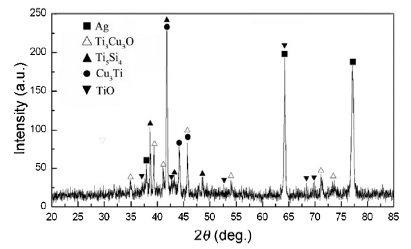
Fig. 9.
XRD spectra of the reaction layer near the SiO2f/SiO2 composite within the joint brazed with 1# filler alloy at 1073 K for 10 min.
In the meantime, the Si atoms released from the reaction (1) would further react with the active element Ti by the following expressions:
Furthermore, based on the XRD pattern shown in Fig. 9, besides the XRD peaks associated with Ag or Ag-based solid solution, Ti3Cu3O, Ti5Si4 and Cu3Ti were also detected at the interface between SiO2f/SiO2 composite and 1# filler alloy. Therefore, the formation of Ti3Cu3O compound in layer “1” as well as TiO, Ti5Si4 and SiO2 compounds in layer “2” can be confirmed.
The microstructure in the central part of the joint can be divided into the following two typical phases: firstly, a white phase (microzone “3”) of Ag(s, s), in which Ag concentration is high up to 81.83%; secondly, a grayish phase of Cu-Ti compound (microzones “4” and “5”), with Cu concentration of 51.77 at.% and 74.03 at.%, respectively.
Therefore, the typical interface structure for the SiO2f/SiO2-Nb joint brazed with 1# alloy at 1073 K for 10 min can be described as the following sequence: SiO2f/SiO2→SiO2+Cu3Ti3O→SiO2+TiO + Ti5Si4→Ag(s, s)+(Cu-Ti)→Nb.
3.3. Effect of brazing time on microstructure and strength of the SiO2f/SiO2-Nb joints
The thickness of the reaction layer adjacent to the SiO2f/SiO2 surface was increased with the prolonging of dwell time at the brazing temperature of 1073 K (Fig. 10, Fig. 11). The Ti concentration in 1# and 2# brazing fillers is higher than 3# filler. So, during the brazing process more Ti atoms in 1# and 2# fillers diffused towards the SiO2f/SiO2 surface, resulting in quicker growth of the reaction layer than 3# filler, for example, after brazing at 1073 K for 60 min, for 1# filler alloy the thickness of the reaction layer is quickly increased to 6.7 ± 0.8 μm whereas that for 3# filler was only 4.2 ± 1.0 μm (Fig. 11).
Fig. 10.
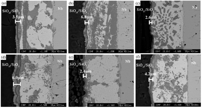
Fig. 10.
Microstructures of SiO2f/SiO2-Nb joint brazed with three Ag-Cu-In-Ti alloys at brazing temperature of 1073 K: (a) 1# alloy, 30 min; (b) 1# alloy, 60 min; (c) 2# alloy, 30 min; (d) 2# alloy, 60 min; (e) 3# alloy, 30 min; (f) 3# alloy, 60 min.
Fig. 11.
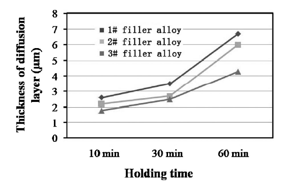
Fig. 11.
Effect of dwell time on thickness of diffusion reaction layer at brazing temperature of 1073 K.
The joint strength was determined by the shear test and presented by the average value. Fig. 12 presents the shear strength of the joints brazed with the three brazing alloys. In general, the joint strength for 1# and 3# brazing fillers appeared to decrease with the prolonging of dwell time at the brazing temperature of 1073 K. Furthermore, the SiO2f/SiO2-Nb joints brazed with 1# brazing filler display the maximum strength level of 25.4-30.9 MPa for the brazing time of 10-60 min, and those for 2# filler give the middle level of 15.2-18.3 MPa, whereas 3# filler exhibits the lowest joint strength (14.9-15.8 MPa). Due to high saturation vapor pressure of Ag element at high temperature, prolonging dwell time at the brazing temperature caused the excessive volatilization of Ag, which probably decreased the ductility of the brazing seams and should be deleterious to the joint strength.
Fig. 12.
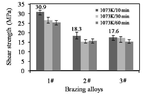
Fig. 12.
Average shear strength of joins brazed with the three alloys.
2# and 3# fillers exhibits lower joint strength than 1# filler. For 1# and 2# filler alloys, their Ti concentration is identical to each other (5 wt%). The evident difference in composition is that the In content in 2# filler is higher than 1# filler. In general, the increase of In content should decrease the plasticity of the AgCu base alloys. During the cooling process from the brazing temperature, the residual thermal stresses within the dissimilar joints would be released to a great extent through the plastic deformation of the residual filler alloy. This should probably be an important reason for the difference in joint strength between 1# and 2# filler alloys.
The lower Ti content in 3# filler decreased the alloy activity, so that the joint strength would be also weakened. Therefore, the joints brazed with 3# alloy show lower strength than the joints brazed with 1# alloy. In one word, sufficient Ti concentration for example 5 wt% Ti in the Ag-Cu-In-Ti filler alloys is needed for the joining of SiO2f/SiO2 composite to Nb metal.
The maximum strength of 30.9 MPa is offered by the joints brazed with 1# filler at 1073 K for 10 min. This strength value is even higher than that of the joints brazed with AgCu-Ti filler at the brazing temperature of 1153 K (26.4 MPa) [10]. The improvement in joint strength is only the first advantage of the newly-developed Ag-Cu-In-Ti system filler alloy. As the second advantage, the brazing temperature for the dissimilar joint has been decreased from 1153 K for Ag-Cu-Ti filler to 1073 K. Undoubtedly, the decrease of brazing temperature is beneficial to relieving the residual thermal stresses within the joint. This should be of great significance especially for joining those large-size components.
After the shear test the joint fracture occurred at the interface between the SiO2f/SiO2 composite and 1# filler as shown in Fig. 13. Though the cracks were originally initiated at the joining interface (zone “A” in Fig. 13(b)), it was evident that the cracks had already propagated into the SiO2f/SiO2 composite substrate (zone “B” in Fig. 13(b)), as some composite pieces closely adhered to the fracture surface at the Nb side.
Fig. 13.
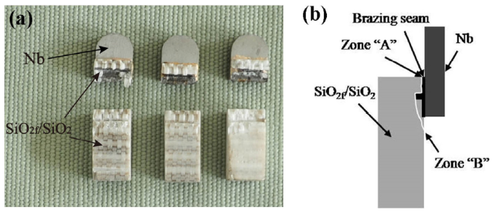
Fig. 13.
Fracture morphologies of SiO2f/SiO2 -Nb joints brazed with 1# filler at brazing temperature of 1073 K for 10 min: (a) fracture photo; (b) fracture diagrammatic sketch.
Among three Ag-Cu-In-Ti filler alloys in this work, the optimum joint strength can be achieved by using AgCu-10In-5Ti (1#) filler alloy. Compared with 2# and 3# filler alloys, the 1# filler alloy has good plasticity activity and it is more suitable than the other two fillers for the joining of SiO2f/SiO2 with Nb. In this study, the high strength of 30.9 MPa for SiO2f/SiO2-Nb joint should be attributed to the Ti concentration of 5.0 wt.% in the filler alloy, as well as the built gradient structure at the joining zone [35,36]. As for the optimum composition of In and Ti, a large number of experimental tests are still needed in future. In the present study, the brazing temperature for the dissimilar joint has been decreased from 1153 K for Ag-Cu-Ti filler to 1073 K, which is beneficial to relieving the residual stress in the joint. This should be of great significance especially for joining those large-size components [37,38]. Furthermore, in the future, the joint properties at 573-773 K would be further studied.
4. Conclusions
In conclusion, three compositions of Ag-Cu-In-Ti filler alloys were newly designed for joining SiO2f/SiO2 to Nb metal. The following conclusions can be drawn from this study:
(1)After being held at 1073 K for 30 min, 1# alloy with the composition of AgCu-10In-5Ti showed the contacted angle of 74° on SiO2f/SiO2 ceramic composite, whereas 3# alloy with 4 wt% Ti gave the value of 86°.
(2)The SiO2f/SiO2-Nb joints brazed with the rapidly solidified 1# filler foils at 1073 K for 10 min exhibited the maximum shear strength of 30.9 MPa at room temperature. However, the average strength of the joints brazed with 3# filler alloy is only 15.8 MPa. It appears that 5 wt% Ti content in the Ag-Cu-In-Ti filler alloys is needed for the joining of SiO2f/SiO2 composite to Nb metal. Additionally, prolonging of dwell time at the brazing temperature of 1073 K tended to decrease the joint strength.
(3)For 1# filler alloy, during the brazing process the active element Ti diffused strongly from the Ag-Cu-In-Ti alloy to the surface of the SiO2f/SiO2 composite, and after brazing at 1073 K for 10 min a typical reaction band had been formed with a thickness of 2-3 μm. This reaction band was composed of SiO2+Cu3Ti3O reaction layer and SiO2+TiO + Ti5Si4 layer.
Acknowledgement
This work was supported financially by the National Natural Science Foundation of China (Nos.5990522, 50475160, 51275497and5140105004).
Reference
Brazing and Soldering, American Welding Society, April 22-25Proceeding of the 5th International Brazing and Soldering Conference (IBSC)2012, Proceeding of the 5th International Brazing and Soldering Conference (IBSC) (2012)

AbstractFrom results obtained over the last 10 years from simple reactive metal/ceramic model systems, a concept of reactive wetting has been formulated which suggests a direct relation between wetting and the physicochemical properties of the interfacial reaction products. The aim of this study is to examine whether this concept can help to understand and rationalise the sometimes conflicting results for the CuAg–Ti/alumina system, which is more complex but important in brazing. This was done using new wetting data generated by sessile drop experiments performed by varying the Ti content in the alloy and the furnace atmosphere (neutral gas and two levels of high vacuum). Experiments were carried out on monocrystalline alumina and also on polycrystalline alumina substrates of varying purity and roughness.]]>

 WeChat