

1. Introduction
Aluminum alloys and aluminum matrix composites (AMCs) are widely used in advanced fields due to its excellent mechanical properties and low density, such as aerospace and transportation materials, as well as military materials in which lower weights would save energy [[1], [2], [3]]. In the past decades, AMCs reinforced with various ceramic phases such as Al2O3, TiB2, Ti3Al, SiC, TiC, carbon nanotubes (CNTs) were extensively investigated [[4], [5], [6], [7], [8], [9]]. However, the mechanical properties of those traditional AMCs are still unsatisfying. In general, the improvement of the strength of these AMCs is at the expense of plasticity, which might be attributed to the intrinsic brittleness of the ceramic reinforcements and the weak interface bonding between matrix and reinforcements.
Graphene, a two-dimensional material with low density, extraordinary Young's modulus (~1 T Pa), excellent mechanical strength (~130 GPa) and outstanding flexibility as well as very large thermal conductivity of 5300 W m-1 K-1, is considered to be an ideal reinforcement to replace the ceramic reinforcements for AMCs to achieve high strength, good toughness and light weight simultaneously for the composites [[10], [11], [12], [13]]. Nevertheless, there are still some challenges that need to overcome, such as achieving uniform dispersion of graphene in the composites, improving the interface adhesion strength and producing graphene economically and in quantity.
Although several novel strategies [[14], [15], [16], [17], [18]] have been adopted to improve the dispersion of graphene in the composites, mechanical milling is still the most economical and practical method for the fabrication of AMCs. By a simple high energy ball milling coupled with hot rolling process, Shin et al. enhanced the tensile strength of graphene/Al composite to 440 MPa [19]. With regard to interface bonding, it was found that interface modification [20,21] was an effective route to improve the interface adhesion strength of the composite. For instance, Zhang’s group reported that Ni exhibits stronger bonding with CNTs than Al [22], and then validated that Ni is a very good element for improving the interface bonding between carbon materials and Al. The other groups found that CNTs decorated with Cu can also promote the interface bonding between CNTs and Al. Therefore, modifying graphene with metal nanoparticles (such as Ni or Cu) should be very favorable for the improvement of interface bonding. Up to now, the post-plating technique was the most frequently used method for modifying graphene with metal. However, this method is costly, time and energy consuming due to the tedious preparation of metal cladding. Furthermore, obtaining a uniform dispersion and tight bonding between graphene and metal cladding is very hard to realize via this technique.
As for the graphene reinforcement, it is extremely difficult to obtain enough perfect single-layer graphene for the fabrication of bulk materials, so graphene derivatives such as few-layer graphene (FLG) [19,23], reduced graphene oxide (rGO) [23,24], graphene nanosheet [25] or graphene-nanoplatelets (GNPs) [26] were extensively utilized as the substitute of graphene in composites. Unfortunately, the existing methods for the preparation of those graphene derivatives are neither complicated nor power-wasting. For example, the Hummers method (one of the top-down approaches) [27] needs numerous steps and lots of acid and water. The exfoliation method usually takes a long time and introduces some impurities into graphene [28,29]. In addition, the raw material of natural graphite used in these methods is a finite resource [30], which would further limit the large-scale applications of graphene in the composite fields. Some other bottom-up methods such as synthesis of graphene on silicon carbide or metal substrates are more unsuitable for the fabrication of composites due to the very little yield of graphene [31,32]. Therefore, it’s of great importance to develop a novel method which can produce graphene derivatives economically and efficiently for preparing graphene-reinforced composites.
In this work, a bottom-up strategy toward metal nanoparticles modified graphene nanoplates (MPGNPs) was developed, which is economically and efficiently with a large capacity by one-step process, and thus very suitable for the preparation of GNP-reinforced composites. This strategy is based on the spray-drying technique combined with the high temperature chemical vapor deposition (CVD) treatment. It is worth mentioning that the decorated metal nanoparticles are easy to achieve uniform dispersion and robust bonding with GNPs due to the one-step in-situ synthesis process, which has obvious advantages over the post-plating technique. Both Ni nanoparticles modified graphene nanoplates (Ni-GNPs) and Cu nanoparticles modified graphene nanoplates (Cu-GNPs) were fabricated by this bottom-up strategy. After that, MPGNPs was compounded with Al matrix by powder metallurgy. The mechanical properties and the interface structure of the MPGNPs/Al composites were investigated in detail. Moreover, the density functional theory (DFT) was performed to calculate the interface binding energy based on our experimental results to further validate the improved interface bonding effect through the introduction of metal nanoparticles at the interface.
2. Experimental
2.1. Preparation of MPGNPs
For the fabrication of MPGNPs, the industrialized spray drying combined with CVD method was employed. Firstly, a homogeneous solution of metal salt (copper nitrate and nickel nitrate were used to obtain Cu particles and Ni particles respectively), glucose and NaCl with a specific molar ratio was spray-dried by the spray dryer. Afterwards, the precursor powders were heat-treated at a high temperature (750 °C for Cu-GNPs and 680 °C for Ni-GNPs) for 2 h under 50 % Ar/H2 atmosphere in the tube furnace. Finally, the product was washed with water to remove the NaCl and reduced at ~400 °C by H2 to eliminate oxygen, then pure MPGNPs powder was obtained.
2.2. Preparation of MPGNPs/Al composites
AMCs reinforced with 0.5 wt.% MPGNPs were fabricated by the powder metallurgy technique. Atomized Al powders with a diameter of 9-11 μm were blended with the appropriate amount of reinforcements by a planetary ball grinder. Stainless steel balls of 6 mm in diameter were used, and the ball powder ratio was 10:1. The mixed powder was ball milled under argon atmosphere at a rotation speed of 360 rpm for 90 min, and an intermittent ball milling strategy was adopted in this work to prevent the overheating of the powders and reduce the structure destruction of GNPs. So, the ball milling process was paused for 30 min after every 10 min of operation. 0.5 wt.% stearic acid was added as a process control agent. The as-obtained composite powder was then cold compacted at a pressure of 500 MPa to form a billet of 20 mm in diameter. After that, the compacted billet was sintered at 630 °C for 60 min in argon atmosphere. At last, the sintered billets were soaked at 550 °C for 30 min and subsequently hot extruded by the punching machine with an extrusion ratio of 16:1. For comparison, monolithic Al and reference samples with 0.25 wt.% Ni (contrast I), 0.25 wt.% GNPs (contrast II) and 0.16 wt.% Cu (contrast III) were also fabricated by the same processing.
2.3. Characterization
Microstructures of Ni-GNPs and Cu-GNPs synthesized by the bottom-up method and their corresponding bulk composite materials were characterized by scanning electron microscopy (SEM, Hitachi S-4800) and transmission electron microscope (TEM, JEM-2100 F). The TEM samples of the bulk samples were fabricated by mechanically grinding and followed ion milling on a Gatan-PIPS695 precision ion polishing system. Thermogravimetry analysis (TGA) (TA PerkinElmer) was performed to study the synthesis process of MPGNPs during CVD and the GNP contents in MPGNPs powders. X-ray diffraction (XRD) with Cu Kα radiation at a wavelength of 1.5406 Å was employed to study the phase components. Raman spectra (Renishaw inVia reflex) was applied to investigate the chemistry structure of MPGNPs powders. Electron back-scattered diffraction (EBSD) technique was used to obtain the grain information of the composites. For the tensile tests, the samples were machined to the dog-bone shaped specimens with a gage length of 15 mm and a gauge diameter of 3 mm. Tensile tests were carried out on a LLOYD EZ20 Tensile Tester with an initial strain rate of 8.3 × 10⁻⁴ s-1 at room temperature. To reduce the test error, three specimens were measured for each material.
3. Results and discussion
3.1. Characterizations of MPGNPs
CVD has been widely used to synthesize graphene on the catalytic transition metal substrates (such as Cu and Ni) [33,34]. In this work, Cu2+ and Ni2+ were also adopted as the catalysts to promote the formation of GNPs and meanwhile as metal precursors for the generation of metal nanoparticles anchored on GNPs. Glucose (C6H12O6) was chosen as the solid carbon source due to its high solubility in water, which can decompose into vapor and carbon only under a high temperature and thus can avoid the introduction of impurity in the product. The schematic diagram of the fabrication process of MPGNPs is depicted in Fig. 1. During the spray drying process, metal salt, glucose and NaCl with a certain proportion were firstly dissolved into deionized water to form a homogeneous solution, which was subsequently atomized into small droplets and dried immediately. At the stage of drying, the sizes of the NaCl cubes were largely restrained, the random but uniform nucleation of cubic NaCl crystals in the droplets would push the glucose and Cu2+ salt (or Ni2+) into the inter-crystal spaces and thus the NaCl cubes were homogeneously coated with an ultrathin C6H12O6-Cu2+ (or Ni2+) complex film due to the high volume concentration of NaCl in the droplets, thereby resulting in the generation of a self-assembled structure consisted of several tens of NaCl@C6H12O6-Cu2+ (or Ni2+) cubes (as shown in Fig. 2(a)), which was subjected to the subsequent CVD process. In order to investigate the synthesis mechanism of MPGNPs during CVD, XRD tests (Fig. 2(d)) were performed on the Cu-GNPs precursor at various temperatures and TGA (Fig. 2(e)) were adopted to explore the chemical changes of the NaCl@C6H12O6-Cu2+ (or Ni2+) during CVD. As demonstrated in Fig. 2(d) and (e), the process could be primarily divided into three stages: temperature below 180 °C (stage 1), a slight weight loss corresponds to the evaporation of crystal water; temperature from 180 °C to 300 °C (stage 2), the main weight loss period was associated with the decomposition of glucose as well as the reduction of the Cu2+ salt; temperature higher than 300 °C (stage 3), this stage is responsible for the transformation of amorphous carbon to GNPs and the removal of some residual oxygen due to the catalytic effect of metal, thus leading to a tiny weight loss. A schematic diagram is inserted in Fig. 2(e) to present an illustration of the transformation process of MPGNPs.
Fig. 1.
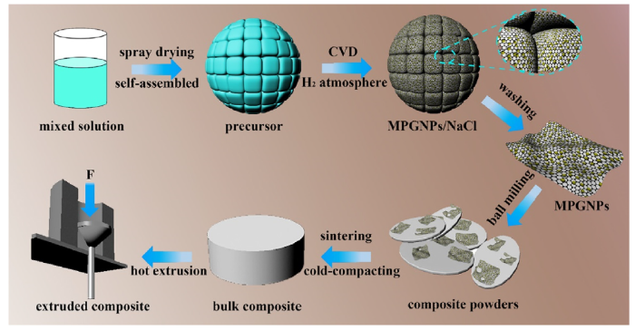
Fig. 1.
Schematic illustration of preparation process of MPGNPs and MPGNPs/Al composites.
Fig. 2.

Fig. 2.
SEM images of self-assembled precursor before (a) and after (b, c) CVD treatment, (d) XRD patterns of Cu-GNPs precursor powders heat-treated at different temperatures, (e) TGA analysis of synthesis process of Cu-GNPs composite powders.
On the basis of the above analysis, during the CVD process at relatively a low temperature (<300 °C), owing to the confinement effects of NaCl cubes, the ultrathin C6H12O6-Cu2+ (or Ni2+) complex film between the interconnected NaCl crystals was transformed into an ultrathin amorphous carbon nanosheets anchored with metal nanoparticles due to the simultaneously carbonization of C6H12O6 and reduction of Cu2+ (or Ni2+) to Cu (or Ni), leading to the in-situ synthesis of assembly constructed by 3D interconnected NaCl cubes covered with carbon nanosheets anchored with uniform metal nanoparticles. As the CVD temperature increased, the ultrathin amorphous carbon nanosheets got graphitized to form GNPs under the catalysis of metal nanoparticles, inducing the synthesis of MPGNPs on the interface between NaCl particles (as displayed in Fig. 2(b) and (c), for a broken self-assembled structure, the GNPs coated on the NaCl particle surface were marked by the black arrows, and the metal nanoparticles could be found on the surface of GNPs easily). Finally, pure MPGNPs powders were obtained after removing NaCl. In contrast, a sample was prepared without using NaCl, with the results are exhibited in Fig. S1 in the electronic supporting information (ESI). It can be seen that without the confinement effect of NaCl, all the carbon source got together and formed huge blocks with very large metal particles embedded.
The phase of the metal nanoparticles in MPGNPs was confirmed by XRD. As presented in Fig. S2 in ESI, not any other peaks except those belonging to nickel (cubic, Fm3m (225)) or copper (cubic, Fm3m (225)) were indexed for Ni-GNPs and Cu-GNPs, respectively, definitely indicating that pure metal nanoparticles were obtained in the MPGNPs as we assumed.
Fig. 3, Fig. 4 show the morphologies of Ni-GNPs and Cu-GNPs, respectively. It can be observed that the as-prepared Ni-GNPs and Cu-GNPs powders exhibit an apparent three-dimensional framework structure that duplicate the NaCl template (Figs. 3(a) and 4 (a)). In addition, the surface of GNPs is homogeneously anchored with a mass of metal nanoparticles with a size of 10-20 nm (as shown in Figs. 3(b) and 4 (b)), and some distinctive wrinkled structure associated with GNPs could be found when enlarged the surface further (as shown in Figs. 3(c) and 4 (c)). This interesting 3D architecture combined with the metal nanoparticles decorated on the surface of GNPs can effectively prevent the stack of GNPs and promote the dispersion of GNPs in metal matrix composites. When the MPGNPs was subjected to sonication for 2 h and then investigated by TEM, as depicted in Figs. 3(d) and 4 (d), the uniform metal nanoparticles are still tightly and evenly anchored on the ultrathin GNPs, well consistent with the SEM observations above. This indicates a very strong interfacial bonding between metal nanoparticles and GNPs walls, which should be attributed to our unique fabrication process and would be very crucial for improving the interface bonding between Al and GNPs. HRTEM images of Figs. 3(e) and 4 (e) taken from typical metal nanoparticle exhibit the spacing of the adjacent lattice being 0.176 and 0.208 nm, which are in good accordance with typical Ni (200) and Cu (110) planes, respectively and also correspond well with the XRD results. Figs. 3(f) and 4 (f) presented the HRTEM observation of the GNPs’ edge, demonstrating an obvious layer structure with a thickness about 5 nm.
Fig. 3.
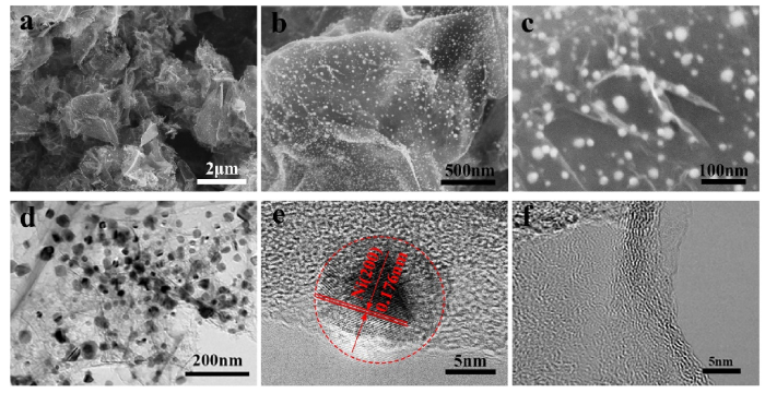
Fig. 3.
SEM images (a-c) and TEM images (d-f) of obtained Ni-GNPs composite powders.
Fig. 4.
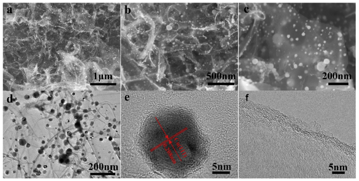
Fig. 4.
SEM images (a-c) and TEM images (d-f) of obtained Cu-GNPs composite powders.
On the basis of the results above, the nickel or copper nanoparticles with uniform size could be successfully in-situ modified on the surface of GNPs by modulating the composition of raw materials and the CVD process. Moreover, this universal method can also be easily extended to the construction of some other catalytic metal nanoparticles anchored on GNPs. The cheap chemical reagents combined with the simple processing enable the mass production of MPGNPs economically and efficiently. What’s more, by introducing metal nanoparticles on the surface of GNPs, the wettability and interface bonding between GNPs and Al matrix can be improved, which would be very beneficial for enhancing the mechanical properties of the composites.
Raman spectroscopy was usually used to characterize the structure of graphene [35,36]. Fig. 5 exhibits the Raman spectra of Ni-GNPs and Cu-GNPs powders. Both Raman spectra presented the characteristic signals of multilayer GNPs with two apparent peaks corresponding to the D band (1330 cm-1) and G band (1590 cm-1). The G band appears from the in-plane C—C bond stretching in GNPs, whereas the D peak is due to the defects introduced in the structure [37,38]. The relative intensity between the D and G peaks (ID/IG) indicates the quality of the graphene [14]. The ID/IG ratio of the Ni-GNPs and Cu-GNPs were about 0.80 and 0.79, respectively, indicating that some defects or disorder structures existed in GNPs. In addition, the thermo-gravimetric analysis was conducted to explore the content of GNPs in MPGNPs powders. As displayed in Fig. S3 in ESI, the content of GNPs was calculated to be ~48 wt.% in Ni-GNPs and 69 wt.% in Cu-GNPs according to the weight loss.
Fig. 5.
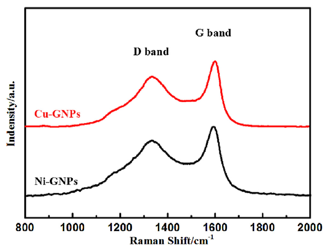
Fig. 5.
Raman spectra of Cu-GNPs (the black line) and Ni-GNPs (the red line) composite powders.
3.2. Microstructures of MPGNPs/Al composite powders
Fig. 6 displays the SEM morphologies of original Al powders (a), the ball milled pure Al powders (b) and the ball milled MPGNP/Al composite powders (c-f). It can be seen from Fig. 6(a) that the original Al powders are roughly spherical with a mean diameter of 10 μm. Only slight deformation has occurred for the Al powders after ball milling due to the low milling energy (Fig. 6(b)). As for the MPGNP/Al composite powders, their three-dimensional framework structure was broken after the ball milling process (Fig. 6(c) and (e)), leading to that the size of MPGNPs decreased to about 500 nm or less and the MPGNPs was uniformly dispersed in Al powders. In addition, it is found that some MPGNPs were attached on the surface of Al powders without any agglomeration (as shown in Fig. 6(d) and (f)).
Fig. 6.
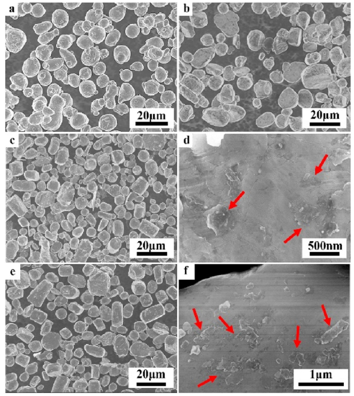
Fig. 6.
Morphology of (a) original Al powders, (b) ball milled pure Al powders, (c, d) ball milled Ni-GNP/Al powders and (e, f) ball milled Cu-GNP/Al powders.
3.3. Microstructures of bulk MPGNPs/Al composites
XRD patterns of pure Al bulk and MPGNPs/Al bulk composites along the extrusion direction are exhibited in Fig. S4 in ESI. All the diffraction peaks correspond well to the crystal planes of Al, and no diffraction peaks of other phases can be detected, which may be due to the low content of GNPs and metal particles beyond the detection of XRD. In addition, the peak intensity corresponding to Al (220) plane is significantly enhanced because of the formation of fiber texture during the extrusion process, which will be further investigated by the EBSD technique.
Microstructure is a major factor that determine material properties, EBSD analysis technique was used to obtain information on the crystal orientation and grain size distribution for both the pure Al and MPGNPs/Al composites. The orientation image microscopy (OIM) map are exhibited in Fig. 7(a-c). It can be observed that both pure Al and composites demonstrate a dominance of the typical fiber texture <111 > . However, when compared Fig. 7(b) and (c) with (a), it is found that the fibrous grain of the composites is much narrower than that of pure Al. Also, there are more recrystallized grains in the composites than those in pure Al. Therefore, it is believed that the incorporation of MPGNPs into composites would promote the recrystallization process by providing additional nucleation sites as well as refine the grain size [39]. With regard to the grain size along the extrusion direction, the average grain size of pure Al and the two composites is 2.10, 2.00 and 1.88 μm in diameter, respectively.
Fig. 7.
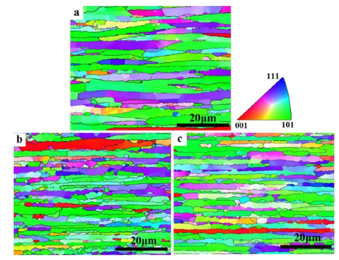
Fig. 7.
EBSD micrographs of (a) pure Al and (b) Ni-GNPs/Al composite and (c) Cu-GNPs/Al composite.
3.4. Interface microstructures of Ni-GNPs/Al composite
A representative TEM image of the Ni-GNPs/Al composite is displayed in Fig. S5 in ESI. It was found that the reinforcements dispersed uniformly in the composite and there are still many nanoparticles anchored on the surface of those reinforcements, verifying that the coating structure of metal nanoparticles on the GNPs was maintained after the whole fabrication process. However, it is found that the shape of the nanoparticles has changed from globose (Fig. 3) to cube in the composite, indicating the phase transformation of Ni nanoparticles during the fabrication process. Those nanoparticles are confirmed to be Al3Ni (Fig. 8(a)), which is consistent with the result in Chen’s work [40]. The difference is that the Al3Ni particles with a size from several nanometers to dozens of nanometers in this work is much smaller than that in Chen’s work (1 μm). This should be the reason that the Al3Ni phase couldn’t be detected by XRD in this work while it was doable in Chen’s work.
Fig. 8.
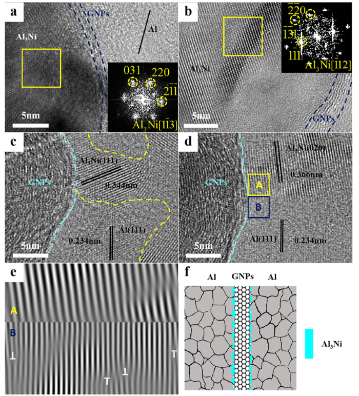
Fig. 8.
(a-d) HRTEM images of the interface of composite (inset: FFT recorded at the marked box). (e) IFFT corresponding to regions marked by boxes in (d). (f) Schematic of GNPs-Al interface structure.
The interface structure of the Ni-GNPs/Al composite was further explored by HRTEM and corresponding Fast Fourier transform (FFT) and inverse Fast Fourier transform (IFFT). As shown in Fig. 8(a), the Al3Ni phase was validated by the electronic diffraction pattern, definitely indicating the formation of Al3Ni interphase in the interface between Al and GNPs. The FFT (as shown in inset of Fig. 8(a)) recorded from the marked box shows (031) (220) and (2$\bar{1}\bar{1}$) diffraction spots of Al3Ni along the [1$\bar{1}$3] zone axis. Hence, the phase can be further determined to be the orthorhombic Al3Ni (Pnma space group, a = 6.598 nm, b = 7.352 nm and c = 4.802 nm, JCPDS card No. 02-0416). HRTEM image of Fig. 8(b) also verifies that Al3Ni layer was formed on the surface of GNPs (as marked with blue dash).
Fig. 8(c) and (d) demonstrate the interface microstructure of three phase (GNPs, Al3Ni and Al), and the corresponding inter-planar spacing was measured and marked in the graph. According to Fig. 8(c), the lattice spacing of the area with a larger inter-planar spacing is measured to be 0.344 nm, which is consistent with the inter-planar spacing of the (111) planes in Al3Ni. In Fig. 8(d), the lattice spacing of the area with a larger inter-planar spacing is measured to be 0.366 nm, which is consistent with the inter-planar spacing of the (020) planes in Al3Ni. The Al3Ni (020) plane is nearly parallel to the GNPs (0001) plane. In both Fig. 8(c) and (d), the lattice spacing of the area with the smaller inter-planar spacing is measured to be 0.234 nm, corresponding to the (111) plane of Al. It can be observed that both the as-formed Al3Ni particles or layers and Al matrix combined tightly with GNPs without any holes or gaps. The combined IFFT image of Fig. 8(e) corresponds to the areas boxed in Fig. 8(d). As can be seen, there also exist some dislocations (“T” shaped symbol) in the Al matrix near the interface, which might be caused by the internal stress between Al and GNPs or Al3Ni. However, there does not exist a specific orientation relationship between the three phases (GNPs, Al3Ni and Al) according to our extensive HRTEM investigations. A schematic diagram of the Al3Ni/Al/GNPs interface structure is presented in Fig. 8(f).
The activation energy of a reaction is the minimum energy required to react, and a lower activation energy means the reaction is more likely to happen. During the sintering process, there are two possible reactions may occur at the interface, the formation of Al3Ni and the formation of Al4C3. Both Ni and C would react with Al, there is a competitive relationship between them. The activation energy of the formation of Al3Ni and Al4C3 at 630 °C is 119 KJ mol-1 and 281 KJ mol-1 [41,42], respectively, which means that the formation of Al3Ni is much easier, and the formation of Al4C3 would be restrained. Al4C3 is a common interfacial compound formed during the fabrication and annealing processes, it is reported that the formation of Al4C3 at the interface would lower the strength of the composite [43,44]. So, it’s really of great benefit that Al3Ni formed at the interface for restraining the generation of Al4C3. Considering the mismatch of the lattice between the three phases (Al, Ni and GNPs), there must form some defect sites at the interface during the heat treatment process. Those vacancies or empty lattice sites would contribute to the diffusion of Al atoms or Ni atoms [20], leading to the formation of Al3Ni phase at the interface. On the basis of the discussion above, the schematics of the possible Al3Ni formation mechanism is displayed in Fig. 9.
Fig. 9.
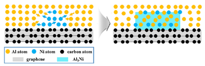
Fig. 9.
Schematics of possible formation mechanism of Al3Ni in Ni-GNPs/Al composite.
3.5. Interface microstructures of Cu-GNPs/Al composite
Fig. 10 displays the TEM images of Cu-GNP/Al bulk composites. It can be found that GNPs was embedded in the grains or through the grain boundaries tightly, as circled in Fig. 10(a) and (c). Double-tilt was employed to further confirm that there exist GNPs in aluminum grains, with the results shown in Fig. 11(a)and (b). As can be observed, the elongated grain, which is consistent with the EBSD result, could be easily recognized after the zone axis was tilt in <011> direction. It should be noted that the area within the white markings in Fig. 11(b) and (d), and Fig. 11(e) and (g) are the same areas. According to Fig. 11(e), the GNPs would locate inside the aluminum grains due to that their surrounding area is all black and no grain boundaries can be found, indicating that this area belongs to one grain. Furthermore, the GNPs were confirmed by scanning TEM (STEM) and the corresponding EDS mapping analysis (Fig. 11(g)), from which the signal of carbon is detected. However, unlike the Ni-GNPs/Al composite, there was not any other phase that can be found on the surface of GNPs or at the interface between GNPs and Al matrix in the Cu-GNPs/Al composite (as shown in Fig. 10(b) and (d) or Fig. 11(f)). Naturally an instant question arises: where is the copper element in the composite? As shown in Fig. 11(g), the STEM image and the corresponding EDS element map indicated that only very weak Cu signal gathered near the GNP area. Considering that the total content of Cu is pretty low (< 0.16 wt.%) and copper has a higher solubility in the Al matrix, it was supposed that some Cu atoms diffused into the matrix and some gathered near the interface.
Fig. 10.
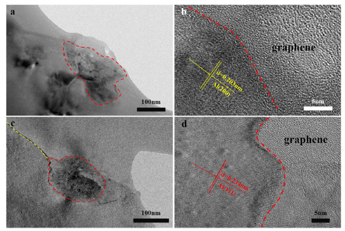
Fig. 10.
TEM images of (a, c) Cu-GNP/Al bulk composite and (b, d) their interface structures.
Fig. 11.
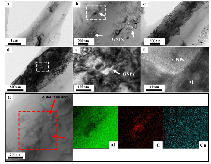
Fig. 11.
Representative TEM images of Cu-GNPs/Al composites. (a, b) Bright-field TEM images without tilt. (c-f) Bright-field TEM images of same area as (a) after tilt in [011] direction. (e) Representative TEM image showing GNPs inside an Al grain. (f) HRTEM image showing “clean” GNPs/Al interface and good bonding. (g) Low magnification scanning TEM (STEM) image of area (e) and the corresponding EDS element map.
Both investigations on the interface microstructure of the Ni-GNPs/Al composite and Cu-GNP/Al bulk composites show that Al4C3 phase was rarely found in these composites. In contrast, lots of Al4C3 phase was found in the contrast II fabricated without introducing metal introduced into GNPs, as depicted in Fig. S6 in ESI. Similarly, Wu et al. tried to inhibit the formation of Al4C3 by introducing high Si content in Al matrix [45]. In addition, it was also found that the Gibbs free energy of Al4C3 formation increased with the addition of Mg in Al and thus inhibited the interfacial reaction between carbon fiber and Al [46]. Since the addition of alloying elements is a common method to control the interfacial reaction between Al matrix and carbonaceous phases [47], it is suggested that the reaction between Al matrix and GNPs could also be inhibited by the introduction of metal particles on the surface of GNPs.
3.6. Quantification of interface binding energy using DFT calculations
For better understanding the effect of the two elements (Ni and Cu) on the interface bonding, we performed DFT calculations by using Vienna Ab initio Simulation Package (VASP) to quantify the interfacial binding energy of the two composites. We adopted the Vanderbilt ultra-soft pseudo potentials for calculating the interaction between the ionic core electrons and the Ceperly-Alder (CA) form of the local density approximation (LDA) for exchange and correlation. The model was based on our previous TEM analysis, as shown in Fig. 12. The interface between GNPs and pure Al was composed of repeated 6-atomic-layer-thick slabs of Al (111) and a graphene sheet (Fig. 12(a)), the interface in the Ni-GNPs/Al composite was composed of repeated 7-atomic-layer-thick slabs of Al3Ni (020) and a graphene sheet (Fig. 12(b)), the interface in the Cu-GNPs/Al composite was composed of Cu doped 6-atomic-layer-thick slabs of Al (111) and a graphene sheet (Fig. 12(c)), all those slabs were placed 2.5 Å below the graphene sheets. The respective model structures have initial lattice mismatch strains of ~0.2 %, 3.1 % and 0.2 %, which were calculated with respect to the graphene lattice. A 20 Å vacuum layer was also introduced at the top of each model to expose only one side of the graphene sheet to the substrate. We adopted a plane wave basis energy cutoff of 450 eV, and used a gamma centered 5 × 3 × 1 Monkhorst-Pack k-point sampling scheme for Brillouin zone sampling. For geometry relaxation, the force on atoms was converged below a threshold of 0.01 eV Å-1. The metal-graphene binding energy is defined as follows:
where Eb, Es, EG and Em are the binding energy, the energy of the total system, the energy of free-standing graphene and the isolated metal slab (Al (111), Al3Ni (020) or Cu doped Al (111)). A is the interfacial area of the system. With this definition, more negative Eb indicates stronger cohesive bonding across the interface.
Fig. 12.
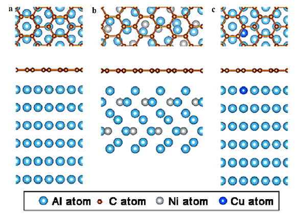
Fig. 12.
First principle calculations of interfacial bonding properties between different substrates and graphene. Bottom view and front view atomic configurations of (a) Al (111), (b) Al3Ni (020) substrates, and (c) Cu-doped Al (111) substrate attached to graphene sheet.
Our DFT calculations present that graphene-Al (111) has an interfacial separation distance of 3.38 Å as compared to 2.89 Å for graphene-Al3Ni (020) and 3.34 Å for Cu doped Al (111)-graphene. The graphene-Al interface has Eb of -1.356 eV nm-2 while it’s -2.985 eV nm-2 and -1.283 eV nm-2 for graphene-Al3Ni interface and Cu doped Al (111)-graphene interface, respectively. The detailed data is shown in Table 1. Those results suggest that the interfacial bonding between graphene and Al3Ni is much tighter than that between graphene and Al, while the Cu doping makes less contribution to the improvement of interface binding between Al and graphene.
Table 1 Detailed values obtained from the DFT calculations.
| System | Es (eV) | EG (eV) | Em (eV) | A (nm2) | Eb (eV nm-2) |
|---|---|---|---|---|---|
| Al/Graphene | -308.39895 | -162.01289 | -145.82607 | 0.41284 | -1.356 |
| Al3Ni/Graphene | -416.83119 | -243.20660 | -171.77599 | 0.61926 | -2.985 |
| Al(Cu)/Graphene | -308.92823 | -162.01289 | -146.38584 | 0.41284 | -1.283 |
3.7. Mechanical properties
Fig. 13(a) and (b) exhibit the engineering strain-stress curves of the monolithic Al, the two composites and the reference samples. The composition and mechanical properties of the specimens are displayed in Table 2. As shown in the Fig. 13(a), the Ni-GNPs/Al composite (about 0.25 wt. % GNPs) displays an ultimate tensile strength (UTS) of 163 MPa, increased by 21 % and 13 % when compared to that of unreinforced Al and contrast II, respectively. The reinforcing efficiency (R) [48]is defined as follows:
where ${{\sigma }_{\text{c}}}$ and ${{\sigma }_{\text{m}}}$ is the yield strength or tensile strength of composite and matrix, respectively, fg is the volume fraction of GNPs, R is 69 for Ni-GNPs/Al composite, which is comparable to or even better than that of most papers reported [19,24,45,49,50]. And it is worth mentioning that the Ni-GNPs/Al composite still presented a remarkable 32 % elongation at fracture, which is even better than that of pure Al, indicating a good strength-ductility combination for this composite. Compared with the Ni-GNPs/Al composite, the Cu-GNPs/Al composite demonstrates a higher tensile strength (180 MPa) but with a lower fracture elongation.
Fig. 13.
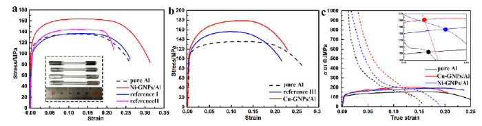
Fig. 13.
(a and b) Tensile engineering strain-stress curves of pure Al, the two composites and the contrast samples (picture of tensile samples was put inset). (c) True strain-stress curves and strain-hardening curves of composites and pure Al.
Table 2 Composition and mechanical properties of specimens.
| Specimen | GNPs content (wt.%) | Ni content (wt.%) | Cu content (wt.%) | UTS (MPa) | Elongation (%) |
|---|---|---|---|---|---|
| Pure Al | 0 | 0 | 0 | 135 ± 3 | 26.0 ± 0.5 |
| Ni-GNPs/Al | 0.24 | 0.26 | 0 | 163 ± 4 | 31.3 ± 0.8 |
| Cu-GNPs/Al | 0.34 | 0 | 0.16 | 180 ± 2 | 22.5 ± 0.5 |
| Reference I | 0 | 0.25 | 0 | 136 ± 3 | 26.1 ± 0.6 |
| Reference II | 0.25 | 0 | 0 | 144 ± 4 | 21.8 ± 0.8 |
| Reference III | 0 | 0 | 0.16 | 156 ± 5 | 21.5 ± 1.2 |
3.8. Strengthening and toughing mechanisms
According to the results above, it is found that the elongation and toughness of the Ni-GNPs/Al composite both increased in comparison to that of pure Al while that of the Cu-GNPs/Al composite decreased. Up to now, very few works have reported the toughening effect of graphene in AMCs. Li et al. improved the toughness of graphene/Al composite via cryomilling [50]. The graphene/Al composites fabricated by Yan et al. also exhibited an improved elongation [51]. The authors attributed the ductility maintaining to the multiply and highly wrinkled structure of graphene. They thought graphene was straightened and flattened during plastic deformation, which in turn led to the improved ductility. Usually, the undesirable inhomogeneous deformation can induce the onset of failure, which severely limits the ductility and would cause the necking instability sets in early [52]. The major cause for the localized plastic deformation is the inability to sustain a sufficient strain hardening rate (Eq. (3)) to prevent the accumulation of large strains in local regions [53].
where Θ is the sufficient strain hardening rate, σ and ε is true stress and true strain, respectively. Moreover, according to Zhang’s opinion, the blockade of graphene nanoribbons (GNRs) to grain slips would effectively prevent a localized deformation along weaker atomic planes, thus promoting the ductility of Cu/GNRs by increasing homogeneity in dislocation slip behavior [54]. Therefore, a high strain hardening rate in the composite is of great importance in improving the ductility.
As shown in Fig. 13(c), it can be seen that the strain hardening rate of both the MPGNPs/Al composites are much higher than that of pure Al, meaning that the addition of GNPs can improve the dislocation storage capacity in the composites. This should be attributed to the inhibition of GNPs on dislocation movement and grain slips along weaker atomic planes. In order to illustrate the pinning effect of GNPs on dislocations, a schematic diagram is displayed in Fig. 14. It can be found that the dislocations will be blocked only by the grain boundaries for pure Al when deformation occurs, while GNPs in composite can provide more interface to hinder the movement of dislocations (as shown in Fig. 11(g)). Thus, the storage capacity for dislocations in the composites can be highly improved and Θ increased for the composites. However, micro-cracks would initiate at the interface between GNPs and matrix once the dislocations reach a certain amount. And the amount of dislocations that can be accommodated at the interface is closely related to the interface strength, tighter interface binding means higher dislocation tolerance. According to our DFT calculation above, the introduction of Ni element improved the interface binding while Cu made no good to it. That’s why the falling speed of Θ of Ni-GNPs/Al becomes slow in the later stage and Ni-GNPs/Al composite shows improved elongation. The uniform elongation is governed by Θ and σ according to Considére criterion, plastic instability occurs when Θ<σ [55]. It’s obviously that Ni-GNPs delays the plastic instability, and improved the uniform elongation. The improved interface binding contributes a lot to improve the critical stress of interface degumming, thus delays the plastic instability. For Cu-GNPs/Al composite, the uniform elongation doesn’t increase for the unimproved interface binding although it has a higher Θ.
Fig. 14.

Fig. 14.
Schematic diagram of pinning effect of graphene on dislocations.
There were two phases (alloying element and GNPs) added in the composites, to clarify the strengthening effect of each phase, reference samples were fabricated by using the same process. As shown in Fig. 13, Ni element with such low content contributes nothing to the strength of the reference sampleⅠwhile Cu element has a positive impact on the strength of the reference sample Ⅲ due to the solid solution effect. Nevertheless, the introduction of Cu reduced the elongation of matrix. Besides, limited strength enhancement was achieved for contrast sample II (with only 0.25 wt.% GNPs added, the same GNP content with composite) with a decrease in the elongation, the mainly reason is the agglomeration of GNPs (as shown in Fig. S7 in ESI). Without the decoration of metal particles on the surface, GNPs is more easily to get stacked and aggregated, leading to the bad mechanical properties. Thus, the strength improvement of MPGNPs/Al composites should be owed to the coupling effect of GNPs and metal nanoparticles.
In general, there are three possible strengthening mechanisms responsible for the enhanced strength of graphene/metal composites, namely grain refinement, dislocation strengthening and load transfer strengthening [19].
First, grain refinement has been regarded as one of the important ways to enhance strength since grain boundaries would act as a hard zone, where dislocations encounter obstacles against their motion [56]. The incorporation of GNPs may refine the metal grains by the pinning effect to grain boundaries. According to the EBSD results above, the grain size of the composites is smaller than that of pure Al. Although there is only a very small difference, the grain refinement should have a positive effect to the strength.
Second, GNPs can act as a barrier to the dislocation motion, leading to the remarkable dislocation accumulation nearby the interface, the higher strain hardening rate of the composite is a direct evidence of this. So, the dislocation strengthening plays an important role in strengthening the composites.
Third, load transfer effect should be considered in graphene/metal composites [19,57]. When the composite is loaded, the matrix is strained and then the strained matrix may transfer the load to reinforcements by means of shear stresses that develop along the reinforcement-matrix interface. The shear forces on the interface parallel to the load direction are balanced with the normal forces on the fiber cross-sections normal to the load direction. When the shear forces are greater than the forces that the interface can carry, if the shear forces are lower than the normal forces that the reinforcements could carry, the interface debonding happens then. The pull-out effect is a typical phenomenon of interface debonding. For graphene, whose mechanical strength is 130 GPa, the shear forces are hardly greater than the normal forces graphene could carry. Thus, improving the interface binding is of great importance for load transfer [58,59]. When the interface binding improved, the max shear forces on the interface improved also. So Al3Ni formed at the interface contributes to the load transfer effect a lot.
As a summary, for both the Ni-GNPs/Al and Cu-GNPs/Al composites, the grain refinement, dislocation strengthening and load transfer strengthening all contribute to its strength improvement. Considering the little change of grain size, grain refinement should play the weakest role among them. The load transfer effect is enhanced in Ni-GNPs/Al composite, in particular, due to the improved interface bonding. In addition, the solution strengthening of Cu element plays a very important role in the Cu-GNPs/Al composite.
4. Conclusions
(1) An easy, scalable and universal bottom-up strategy for the mass production of MPGNPs was proposed, Ni-GNPs and Cu-GNPs composite powders were fabricated by this method successfully.
(2) Al matrix composites reinforced with Ni-GNPs or Cu-GNPs were fabricated via powder metallurgy. The dispersion of GNPs in Al matrix was highly improved due to the metal nanoparticles attached on its surface. Moreover, the introduction of metal particles on the surface of GNPs could also prevent the formation of Al4C3 effectively.
(3) Ni-GNPs/Al composite exhibited simultaneously improved strength and toughness compared with unreinforced Al. Al3Ni particles/layers formed at the GNPs/Al interface in the Ni-GNPs/Al composites is very favorable for boosting the interface bonding and enhancing the load transfer efficiency of GNPs according to our DFT calculations. A strong interfacial bonding could also boost the toughness of the composites.
(4) Cu element has little effect on interface bonding whereas it has a strong solid solution strengthening effect. The present results can guide the rational interface design of graphene/Al composites with enhanced mechanical properties.
Acknowledgements
This work was financially supported by the National Natural Science Foundation of China (Grant Nos. 51771130, 51531004, and 51422104), the Tianjin youth talent support program, the Tianjin Natural Science Funds for Distinguished Young (Grant No. 17JCJQJC44300) and the Tianjin Science and Technology Support Project (Grant No. 17ZXCLGX00060).
Appendix A. Supplementary data
Supplementary material related to this article can be found, in the online version, at doi:https://doi.org/10.1016/j.jmst.2019.09.045.
Reference

AbstractAluminum alloys reinforced with silicon carbide (SiC) particles have been studied extensively for their favorable properties in structural and thermal applications. However, there has been only limited research into investigating the loading limit of a reinforcement phase of a metal matrix composite. In this paper, semi-solid powder processing (SPP), a fabrication method that exploits the unique behavior of a solid–liquid mixture, was used to synthesize SiC particle-reinforced Al6061. A high volume loading (>45 vol.%) of SiC in Al6061 matrix was investigated by varying the SiC loading volume fraction, forming pressure, SiC particle size and Al6061 particle size. The compaction and synthesis mechanism of the composite by SPP was discussed based on reinforcement phase compaction behavior and processing parameters. Microstructure, hardness, fracture surface and X-ray diffraction results were also analyzed. Results showed that SPP can achieve over 50 vol.% loading of SiC in Al6061 matrix with near theoretical density.]]>

 WeChat