

1. Introduction
Nickel-based single-crystal (SC) superalloys are a kind of high-temperature materials used in gas turbine engines for blades and vanes due to their excellent mechanical properties at elevated temperature [1,2]. During the service of these high-value components, there are always certain damages such as platform cracks and blade tip erosion arising which severely limit their life expectancy. Therefore, it is of great economic benefit to reuse the damaged SC components through reparation, instead of treating it like a scrap [3]. Conventional welding methods, such as gas-tungsten-arc welding, easily result in stray grain formation and cracking [4]. Therefore advanced repair methods are essential to optimize the resuse of the damaged SC component.
The additive manufacturing (AM) technologies, such as Laser metal forming (LMF) and Selective laser manufacturing (SLM), have a definite advantage in terms of the rapid forming of SC components and thus have been researched widely in recent years [[5], [6], [7], [8], [9], [10], [11]]. Due to rapid solidification during this process, it is easy to obtain laser cladding with a fine microstructure, such as fine dendritic structure, fine carbides, fine γ′ phase, etc., even the SC components without (γ+γ′) eutectic can be produced, provided that the cooling rate is high enough [6]. The AM is layer-by-layer techniques where a powder layer is applied to a building area and molten by a moving heat source. In this process, the laser cladding grows epitaxially from the substrate [3,[5], [6], [7]], which is a necessary condition for AM to produce single crystal layer by layer.
However, the achievement of SC laser processing is not easy. Many studies [3,[5], [6], [7]] have shown that the successful processing of SC superalloys needs to inhibit the nucleation and growth of stray grains in the supercooled region ahead of the solid-liquid interface during solidification, that is, to inhibit the columnar-to-equiaxed transition (CET). Gäumann et al. [3] developed the analytical CET model for rapid dendritic growth during laser process. The relationship between the CET and solidification parameters can be expressed as follows [3]:
where G is the temperature gradient in the liquid, V is the solidification velocity of the columnar front, N0 is the nuclei density of the alloy, ϕ is a certain volume fraction of equiaxed grains, a is material dependant constant.
Laser forming of a nickel-based superalloy, especially with a large amount of aluminum and titanium, is easily limited by their crack sensitivity. This is because these alloys exhibit low plasticity at about 700 °C [3]. In order to deal with the crack problem during the laser additive process, the higher preheating temperature has to be undertaken [3]. However, the higher preheating temperature will lower the average G3.4/V ratio [3].
It can be seen from the Eq. (1) that an increase in the G3.4/V value will directly lead to an increase in ϕ. So higher preheating temperature increases the tendency to form equiaxed crystal or stray grain [3,5]. As a result, the AM process parameters window is very narrow, and it is challenging to fabricate nickel-based single crystal superalloys by AM technologies. Thus, a lot of research work is focused on the control of strain grain, crack and dendrite deflection [[12], [13], [14], [15], [16], [17], [18], [19]], while the (γ+γ′) eutectic and its effects on mechanical properties of repaired SC samples are rarely reported.
In this work, a pulsed-laser beam was used to repair a DD32 s-generation SC plate. The microstructure of the SC thin-walled parts repaired by the laser processing was studied, and the tensile tests were carried out from 660 to 1100 °C to study the mechanical properties of the repaired DD32 SC alloy.
2. Experimental procedure
The DD32 plate, 18 mm × 2.8 mm × 23 mm, for substrate was machined from a conventional directional solidification cast, whose withdrawing rate was 5 mm/min. The longitudinal direction of DD32 castings is approximately parallel to [001] crystalline orientation and perpendicular to its axis cross-section, so as to obtain the plate substrate whose surface is nominally parallel to (001) plane. The chemical composition of the substrate is shown in Table 1. The nominal chemical composition of the DD32 powder is the same as that of the substrate. Before repairing, the substrate was exposed to a solution treatment of 1290 °C × 4 h/AC to homogenize the substrates [5]. The surface of all substrates is polished with 150 mesh sandpaper and washed with ethanol before LMF.
Table 1 Main chemical composition of DD32 alloy (wt%).
| C | Cr | Co | W | Mo | Al | Nb | Ta | Re | Ni |
|---|---|---|---|---|---|---|---|---|---|
| 0.12-0.18 | 4.30-5.60 | 8.00-10.00 | 7.70-9.50 | 0.80-1.40 | 5.60-6.30 | 1.40-1.80 | 3.50-4.50 | 3.50-4.50 | Bal. |
LMF experiments were carried out using CO2 laser with a beam diameter of about 2.0 mm. All the LMF repairing experiments were carried out with a laser power of 2 kW and a powder feeding rate of 10 g/min. Pulse-laser working condition, on and off as showing in Fig. 1(a), was controlled by G code. The beam-on time (t1-t0) was 0.16 s and the beam-off time (t2-t1) was 0.4-0.6 s. The laser forming processing is shown in Fig. 1(b). An argon jet is used to transport the DD32 alloy powder between 25 and 48 μm, which acts as a protective gas. The size of the repaired DD32 single crystal sample, as shown in Fig. 1(c), is 44 mm in length, 18 mm in width, and 3 mm thick (Table 2).
Fig. 1.
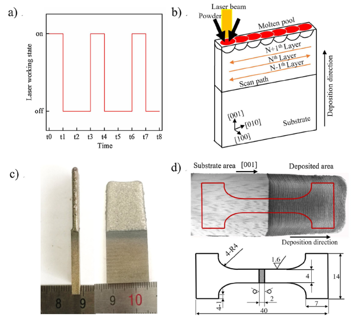
Fig. 1.
Laser working state (a), schematic diagram of the laser scanning path, (b) repaired DD32 alloy sample (c) and specimen geometry for tensile test (d).
Table 2 Yield strength (YS), ultimate tensile strength (UTS) and strain of each sample at each temperature, and mean and std of YS, UTS and elongation of the samples in each temperature.
| Temperature (°C) | YS (MPa) | UTS (MPa) | Elongation (%) | ||||||
|---|---|---|---|---|---|---|---|---|---|
| Mean | Std | Mean | Std | Mean | Std | ||||
| 660 | 890 | 907.6 | 11.7 | 1031 | 1054.8 | 12.7 | 7.5 | 6.4 | 0.9 |
| 901 | 1054 | 7.5 | |||||||
| 925 | 1066 | 6 | |||||||
| 910 | 1058 | 5.5 | |||||||
| 912 | 1065 | 5.5 | |||||||
| 760 | 937 | 929.2 | 15.9 | 1116 | 1118.4 | 16.1 | 15 | 12.4 | 2 |
| 952 | 1129 | 13 | |||||||
| 918 | 1142 | 9 | |||||||
| 906 | 1095 | 12 | |||||||
| 933 | 1110 | 13 | |||||||
| 900 | 669 | 661.2 | 16.7 | 878 | 851.4 | 15.6 | 16 | 13.9 | 1.4 |
| 683 | 845 | 15 | |||||||
| 660 | 854 | 12 | |||||||
| 662 | 830 | 13 | |||||||
| 632 | 850 | 13.5 | |||||||
| 1000 | 513 | 517.6 | 13 | 662 | 657.6 | 16.3 | 15 | 14.5 | 2.1 |
| 500 | 635 | 16 | |||||||
| 540 | 685 | 13.5 | |||||||
| 520 | 655 | 11 | |||||||
| 515 | 651 | 17 | |||||||
| 1100 | 416 | 405 | 13.5 | 425 | 425.6 | 13.3 | 15.5 | 13.9 | 2.4 |
| 395 | 425 | 17 | |||||||
| 407 | 415 | 10 | |||||||
| 422 | 426 | 12.5 | |||||||
| 385 | 450 | 14.5 | |||||||
The plate-like tensile specimens (Fig. 1(d)) with the gauge length of 18 mm and width of 4 mm were machined from the repaired single crystal plate in which the volume fraction of the laser deposited zone is set to 50 %. The tensile tests were performed with a constant strain rate of 0.36 mm/min until fracture happened on MTS E45.105 Electronic Universal Material Testing Machine. Five different groups of temperature tests (660, 760, 900, 1000, 1100 °C) were carried out to study the effect of temperature on tensile properties.
The microstructures of the investigated samples were characterized by using optical microscopy (OM: Axio Observer 3 m) and scanning electron microscope (SEM: JMS-6301 F). All samples for SEM and OM were mechanically polished and chemically etched with 20 g CuSO4+100 ml HCl +80 ml H2O solution. The Image-Pro Plus software was used to measure the dendrite spacing and the volume fraction of γ′. The tensile-ruptured samples for transmission electron microscopy (TEM) observation were cut from the side of the deposits close to the fractured surface and parallel to the loading axis. All samples for TEM were ground to 40 μm and then electrolyzed by twin-jet polishing in 90 % ethanol and 10 % perchloric acid at 20 V and -20 °C. JEM 2100 TEM was used to examine the microstructure of all the specimens to study the micro-mechanism of tensile deformation.
3. Results
3.1. Microstructures of repaired single crystal samples
The typical cross-sections (perpendicular to the scanning direction) of the DD32 single superalloy repaired by LMF is shown in Fig. 2. No crack was found in the deposited zone in this study. The traces of layer-by-layer epitaxial growth produced by laser processing clearly exhibited in Fig. 2(a). The average thickness of the layer was about 300 μm. A clear interface between layers could be seen in low magnification OM images. The thickness of the heat-affected zone (HAZ) was 147 μm.
Fig. 2.
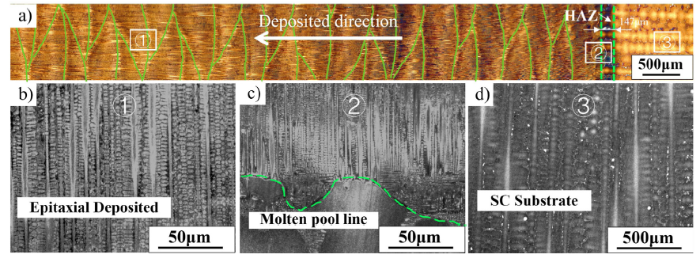
Fig. 2.
Microstructures of the repaired DD32 single superalloy (a), dendrites at the deposited area (b), at the joint area (c) and at the substrate area (d). (b), (c) and (d) are taken from the area of box ①, ② and ③ in (a). Green thin lines in (a) represent the pool line. The area between green dotted lines in (a) draw HAZ. The green dotted line in (c) represents the pool line.
The dendrite direction in the deposited area was the same as that in the substrate area achieved by epitaxial growth, shown in Fig. 2(b) and (c), but the primary dendrite spacing (17.2 μm) was apparently smaller than that in the substrate area (307 μm). The mean primary dendrite spacing in the deposited area was about 17.2 μm, which was only 5.6 % of the primary dendrite spacing in the substrate area. It was suggested that such a fine dendrite structure should increase the homogeneity of the composition in the deposited area [20]. Moreover, the primary dendritic spacing of the initial layers increased with the increase of the number of cladding layers due to the decrease of cooling rate. The mean secondary dendrite arm spacing at initial cladding layers and high cladding layers in the deposited area were 3.3 μm and 2.1 μm, respectively.
The size of γ′ and carbides in the deposited area was also smaller compared with that in the substrate area, as shown in Fig. 3(a) and (b). The mean size of γ′ at the core and the interdendritic region in the deposited area were 61.1 nm and 39.9 nm, respectively, and the volume fractions of γ′ at the core and the inter-dendritic region in the deposited area were about 65 % and 51 %, respectively. In the substrate area, the mean size of γ′ was about 193 nm, and the volume fraction of γ′ was approximately 60.3 %.
Fig. 3.
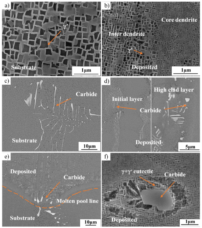
Fig. 3.
SEM images of γ′ (a, b) and the MC carbide (c, d, e, f). (a) and (c) at the substrate area, (b) and (d) at the deposited area, (e) at the molten pool line between deposited and substrate, (f) at high cladding layer of the deposited area.
The morphology of carbides in the deposited area was also different from that in the substrate area. The carbide in DD32 SC superalloy has been proved to be mainly MC type by Yu et al. [21]. The shape of the MC carbide in the substrate, shown in Fig. 3(c), was Chinese-script carbides, while the shape of the MC carbide in the deposited area, shown in Fig. 3(d), was fine reticulate and blocky, and the size of the MC carbide increased as the cladding layer rose (shown in Fig. 3(d)). Some of the blocky carbides were found to be wrapped in (γ+γ′) eutectic, as shown in Fig. 3(f). At the interface of the joint, tadpole-like MC carbide could be found, as shown in Fig. 3(e). It indicated that the carbides at the interface on the side of the deposited area dissolved partially compared with that in the substrate. The temperature at the bottom of the molten pool had reached the melting point of the carbide, which leads to its dissolving. However, due to the short laser heating time and rapid solidification, the carbide at the molten pool line couldn’t be dissolved completely, besides, due to the presence of temperature gradient in the molten pool, the temperature at the molten pool line only reaches the melting point of the alloy, less than the temperature inside the molten pool, which causes the carbide away from the molten pool line to dissolve more until it is completely dissolved, eventually producing the tadpole shape carbide.
Fig. 4.
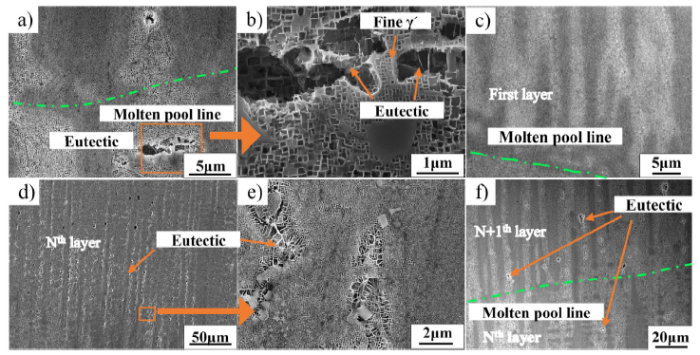
Fig. 4.
SEM images of the eutectic at the bottom of molten pool line (a, b), at first layer (c), at Nth cladding layer (d, e), on both sides of the molten pool line (f). The magnification of the area with orange boxes in (a) and (d) is shown in (b) and (e).
The volume fraction of the porosity in the deposited area and the substrate area has been measured by Image-Pro Plus. It was about 0.19 % in the deposited area, which was more than that in the substrate (0.11 %). The size of the porosity in the substrate area (15.6 μm) was distinctly bigger than that in the deposited area (3.2 μm), as shown in Fig. 5.
Fig. 5.
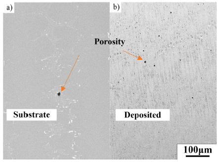
Fig. 5.
SEM images of porosity at substrate area (a) and deposited area (b).
Beside of the deposited area, the microstructure of γ′ phase at the HAZ in the joint area was also investigated, as shown in Fig. 6. The γ′ phase of the core and inter dendrite region in the substrate area exhibited in Fig. 6(e) and (f). The residual (γ+γ′) eutectic can be found in the inter dendrite region. Fig. 6(a)-(d) shows the SEM images of the γ′ phase among the core and inter dendrite in the HAZ. The fine γ′ particles precipitated in the γ channel, and there were many fine γ′ phase around the residual eutectic in the inter dendrite region. As the γ′ phase close to the molten pool line, the (γ+γ′) eutectic even disappeared at the inter-dendrite region. These results indicated that the temperature in the HAZ was high enough to dissolve the γ′ phase and (γ+γ′) eutectic. In the process of cooling, the γ phase reached below the solubility curve and formed a supersaturated solid solution, resulting in a diffusion-type desolvation precipitation phase transition. According to the principle of phase transformation, the critical nucleation work ΔGc are given as follows [35]:
where ρ is the interfacial energy per unit area of the γ/γ′ interface, and ΔGV and ΔGε are the changes in chemical-free energy and strain energy caused by the precipitation of the γ′ phase per unit volume, respectively. ΔX indicates the supersaturation of solute in γ solid solution., and ΔT indicates the supercooling degree of supersaturated γ solid solution.
Fig. 6.
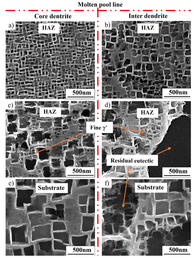
Fig. 6.
SEM images of γ′ in the core-dendrit (a, c, e) and inter-dendrite region (b, d, f). (a) and (b) are at HAZ close to the molten line, (c) and (d) are at the middle of the HAZ, (e) and (f) are at substrate area.
According to Eqs. (2)-4), increasing the degree of supersaturation and supercooling will reduce the nucleation work ΔGc of γ'. The dissolution of γ' and (γ+γ′) eutectic increases the γ channel supersaturation, and the laser process has a faster cooling rate, so the supercooling ΔT is also large. These will all reduce nucleation work ΔGc of γ'. At the same time, the cooling rate is relatively fast, the phase transition time is relatively short, the γ′ forming elements are too late to diffuse to the γ/γ′ interface, so the nucleation of γ′ is performed in the γ channel. The growth time is short, so the size of the precipitated γ′ is fine.
The tensile tests were carried out at 660, 760, 900, 1000 and 1100 °C, and the results are exhibited in Fig. 7 and Table 2. The true-strain curves are shown in Fig. 7(a). It could be seen that the significant work hardening took place following the yield point at 660 and 760 °C. At 900 °C, there were obvious upper yield point and lower yield point, and obvious work hardening occurred after the lower yield point. At 1000 °C, a prominent work hardening happened following the yield point and then the flow stress gradually decreased until rupture. At 1100 °C, the flow stress gradually decreased after yield point. From 660-760 °C, the yield strength and ultimate strength, shown in Fig. 7(b), both increased. When the temperature rises above 760 °C, the ultimate strength and yield strength decrease considerably. The value of the elongation at different temperatures is shown in Fig. 7(c). The elongation increased significantly from 660 to 760 °C. It increased a little and reached the maximum at 1000 °C then declined as the temperature increased from 1000 to 1100 °C. The strain-hardening exponent (n) obtained from the tensile curves at different temperatures were shown in Fig. 7(d). The n value decreases little between 660 and 760 °C, then it rapidly increased to a maximum at 900 °C, as the temperature rose to above 900 °C, the n value decreased quickly. The value of n was below zero at 1100 °C, which indicated the trend of work hardening was smaller than that of recovery softening.
Fig. 7.
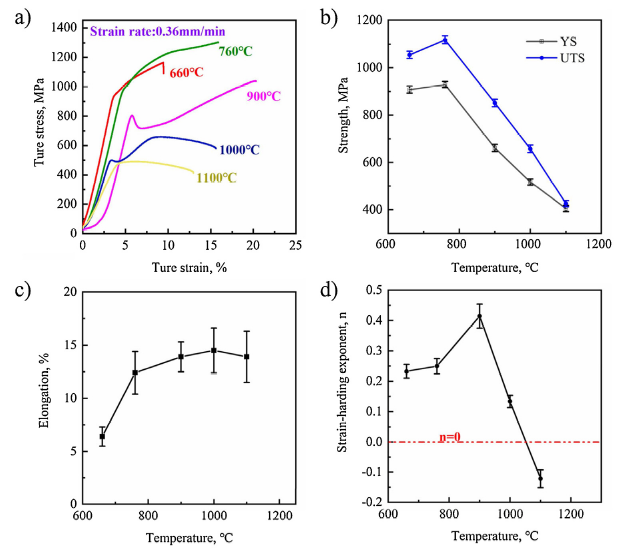
Fig. 7.
Tensile results of repaired DD32 single crystal at various temperatures: (a) typical tensile true stress-strain curves; (b) tensile strength; (c) elongation; (d) strain-hardening exponent.
3.2. Microstructures of the tensile-ruptured samples
The microstructures of the tensile fracture surface and the longitudinal section of the fractured specimen, as shown in Fig. 8, Fig. 9, Fig. 10, were observed by SEM. By comparing the primary dendrite spacing of the longitudinal section of the fractured specimen, it can be suggested that fracture occurred at the substrate area under moderate temperature tensile test (660, 760 °C) while fracture occurred at the deposited area under high-temperature tensile test (900, 1000 and 1100 °C). That is to say, the strength of substrate area and deposited area of the repaired SC superalloy varied under different temperature tensile test. The fracture behaviors were distinctly different from 660 to 1100 °C. In Fig. 8(a), apparent dendritic features were observed on the fracture surface. The fluvial cleavage fracture indicated the cleavage fracture mode at 660 °C. The fracture surface characteristics at 760 °C, shown in Fig. 8(b), was the same as that at 660 °C, which meant that the fracture mode under this condition was also cleavage. The MC carbide, in the substrate area, had broke and was distributed along the fracture from 660 to 760 °C as shown in Fig. 9(a1), (b1), (a2) and (b2). Due to most MC carbides was distributed in the interdendritic region. The interdendritic region became the crack source of the tensile crack, so the apparent dendrite morphology could be observed in the fracture surface.
Fig. 8.
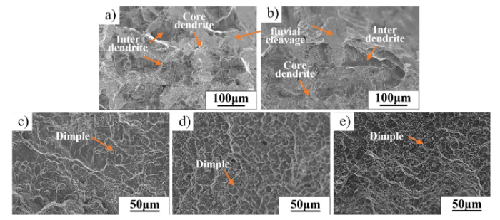
Fig. 8.
SEM images of tensile fractured surface at (a) 660 °C, (b) 760 °C, (c) 900 °C, (d) 1000 °C and (e) 1100 °C.
Fig. 9.
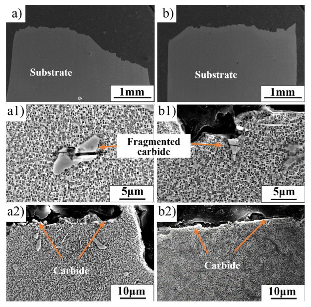
Fig. 9.
SEM images of the vertical section of tensile-ruptured samples at 660 °C (a, a1, a2) and 760 °C (b, b1, b2) of substrate area. (a1) and (b1) show the broken MC carbide. (a2) and (b2) show the MC distributed along the fracture surface.
Fig. 10.
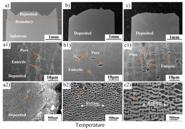
Fig. 10.
SEM images of the vertical section of tensile-ruptured samples at 900 °C (a, a1, a2), 1000 °C (b, b1, b2) and 1100 °C (c, c1, c2) of deposited area. (a1, b1, c1) show the pore. (a2, b2, c2) show the γ′ networks.
At 900, 1000 and 1100 °C, the fracture surface was characterized by the combination of the dimple and cleavage crystal planes (Fig. 8(c)-(e)). The fracture mode was a typical microporous aggregation fracture, shown in Fig. 10(a1)-(c1). With the increase in temperature, the micropores were more obvious. These micropores were mainly distributed at inter dendrite and formed from the defect. There is no doubt that solidified porosities were ready-made micropores. Besides, it was shown that during the high-temperature tensile test, the micropores were formed and connected mainly along with the eutectic interface, resulting in the fracture of the alloy. Therefore, the fine (γ+γ′) eutectic was also the weak region of the deposited area during the high-temperature tensile test.
where b is the Burgers vector, S is the shear modulus, and h is the width of the γ channel. According to the Eq. (1), the yield strength decreases as the γ channel width (h) increases. The γ channel width reached a maximum at 1100 °C. Therefore, as the temperature increased, the yield strength decreases and reaches the minimum at 1100 °C. This is similar to Cui’s report [23].
3.3. Deformation microstructures
The microstructures on the side of deposited after fracturing under different temperatures (760, 900, 1100 °C), were observed by TEM, as shown in Fig. 11. The dislocation sheared the γ' phase and formed a stacking fault, which was the main deformation mechanism of the tensile specimen at 760 °C (shown in Fig. 11(a)). A stacking fault formation mechanism was proposed in Refs. [[24], [25], [26]] with the following reaction:
Fig. 11.
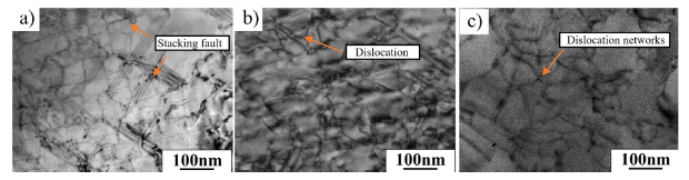
Fig. 11.
TEM images of deformation microstructures of the repaired DD32 single crystal at (a) 760 °C, (b) 900 °C and (c) 1100 °C.
Fig. 11(a) illustrates the formation of stacking faults. When the stress was high enough, the a/3〈 $\bar{1}$12〉 dislocation sheared into the γ′ precipitates leaving behind superlattice intrinsic stacking fault (SISF), and the remaining a/6〈$\bar{1}$12〉 Shockley dislocation at the γ/γ′ interface.
At 900 °C, the dislocation loop was observed, indicating that the main deformation mechanism at this temperature was dislocation bypass. At 1100 °C, dislocation networks formed, as shown in Fig. 10(c). The dislocation net shape was an irregular quadrilateral, whose side line direction was parallel to 〈110〉 directions. The mechanism of the formation of dislocation network is shown in Fig. 12(b). a/2 〈110〉{111} dislocations slipped in the γ matrix and bypassed γ′ particle, leaving the dislocation network at the γ/γ′ interface. The deformation process of the tensile test was similar to the deformation behavior of the initial creep stage, and the flow stress of the tensile test was much higher than the creep stress, which would lead to the formation of a dislocation network during the tensile test [23]. Considering that the tensile test took a short time, these matrix interface dislocations did not have enough time to adjust the dislocation line from the typical < 110 > slip direction to the direction of [100] and [010] which release the internal stress to the greatest extent, so it was impossible to form regular dislocation networks.
Fig. 12.
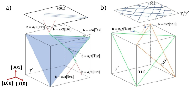
Fig. 12.
Illustration of the formation mechanism of stacking fault (a) and formation mechanism of dislocation network (b).
4. Discussion
4.1. Microstructure in the deposited area
The solidification structure of alloy is closely related to the solidification parameters. The primary dendrite arm spacing (λ1) dendrite spacing can be expressed by the Kurz-Fisher (KF) model [27]. The equation is given as follows:
where D is the diffusion coefficient in liquid, ΔT0 is the liquidus-solidus range at initial alloy concentration, V is the rate of liquidus-solidus interface movement, k is the equilibrium distribution coefficient, Γ is the Gibbs-Thomson coefficient, G is the interface temperature gradient.
Generally, the temperature gradient G is about 105-107 K/m in laser processing. And the rate of liquidus-solidus interface movement is the order of cm/s [3]. The G and the V of the traditional direction solicitation are 104-105 K/m and10-2 cm/s, respectively [28,29]. The temperature gradient and solidification speed of the laser cladding are much larger than that of the traditional casting, and according to Eq. (2). Therefore, the primary dendrite spacing in the deposited area is much smaller than that in the substrate area. The composition of Re in the deposited area is shown in Fig. 13. Although the solution treatment of the substrate was carried out, the element segregation in the deposited area is still smaller than that in the substrate area. This indicated that the segregation range of elements decreases distinctly with the decrease of primary dendrite spacing similar to the result in Ref. [20].
Fig. 13.
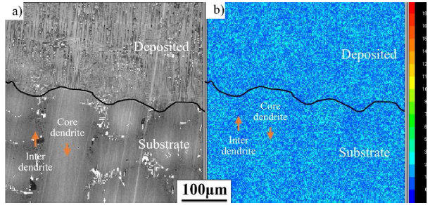
Fig. 13.
SEM image of the joint area (a) and EPMA image of Re element distribution in the joint area (b).
where k2 and m are constants. For nickel-base superalloy, the value of k2 = 4.7 × 10⁻² mm K1/3 s-1/3 and m= -0.4. The mean secondary dendrite arm spacing at initial cladding layers and high cladding layers in the deposited area were 3.3 μm and 2.1 μm, respectively. The secondary dendrite arm spacing in the substrate was 56.8 μm. So the mean cooling rate of laser process at initial layers and high cladding layers are 2374 K/s and 765 K/s, respectively, and the cooling rate of the casting process in the substrate is 0.6 K/s. The cooling rate of LMF process is much higher than that of the traditional casting, and as the LMF process goes on, the cooling rate decreases gradually, this is because the temperature of substrate keeps rising under the continuous laser heating. In this study, there was no visible eutectic in the first cladding layer (Fig. 4(c)), while a large number of fine (γ+γ′) eutectics distributed in the high cladding layers (Fig. 4(d)). This indicated that the change of cooling rate not only affects the secondary dendrite arm spacing, but also affects the (γ+ γ′) eutectic. The relationship between cooling rate, eutectic content and deposited height can be described as shown in Fig. 14(a).
Fig. 14.
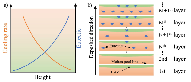
Fig. 14.
(a) Schematic of the evolution of the cooling rate and volume fraction of (γ+ γ′) eutectic and (b) illustration of the distribution of the (γ+ γ′) eutectic with the increase of deposited height.
In the study on the solidification path of SC nickel-base superalloys, Liang et al. [6] note that the solidification process of superalloy can be divided into four steps: (i) L→γ0, (ii) L→γE+MC, (iii) L+MC→(γ+γ'), (iv) L→(γ+γ'). The third step is the peritectic reaction. Whether the C atom and γ′ formers can fully diffuse is the key factor for its reaction. If the cooling rate is high enough, there is no time for C atoms and γ′ formers to spread sufficiently, step (iii) will not happen, and solidification will be finally completed by forming the (γE +MC) eutectic: L→γE+MC. Otherwise, (γ+ γ′) eutectic formed at the end of solidification: L→(γ+γ'). The cooling rate in the first cladding layers was obviously faster, and it was fast enough to discourage the C atoms in solid and γ′ formers in liquid diffusion, resulting in γ+γ' free in the initial layers. Meanwhile, MC carbides mainly exist in the form of fine branching morphology at inter dendrites (Fig. 3(d)). At high cladding layers, the cooling rate was relatively small, thus, a large amount of eutectic was formed after solidification, and the carbide wrapped in the (γ+γ′) eutectic were found caused through the reaction of (iii), similar to Liang et al.’s research [6].
However, due to the high temperature at HAZ in Nth cladding layer caused by N+1th cladding layer, the eutectic at the top of the Nth layer dissolved into the γ channels, resulting in the less (γ+γ′) eutectic at the top of the Nth layer, as shown in Fig. 4(f). It could be found that fine γ′ was distributed at the edge of the eutectic at the top of the Nth layer, as shown inFig. 4 b, which proved that the change of the (γ+γ′) eutectic in the Nth layer was the same as that at the HAZ in the joint area. The distribution of eutectic with increasing height can be described as shown in Fig. 14.
Although the rapid cooling rate in the first layer can avoid (γ+γ′) eutectic formation, the cooling rate of the molten pool in the subsequent forming processing is significantly reduced due to continuous laser heating, resulting in (γ+γ′) eutectic formation. The external cold source can increase the cooling rate, but a high cooling rate will increase the accumulation of residual thermal stresses [33] which is easy to cause the crack. This is not desirable. In order to reduce (γ+γ′) eutectic, the thickness or deposited height can be reduced appropriately, so that the heat affected zone will cover the whole layer. In addition, Liang et al.’s research [34] shows that reducing the deposited height can be achieved by reducing heat input or reducing the amount of powder feeding rate, and the cooling rate will rise as less laser energy is applied. This will provide ideas for controlling the (γ+γ′) eutectic of the repaired SC superalloy.
4.2. Tensile properties of the repaired SC
The samples tested from 660 to 760 °C fractured at the substrate area, however, the ones tested at temperatures from 900 to 1100 °C fractured at the deposited area. The mechanism of fracture is shown in Fig. 15.
Fig. 15.
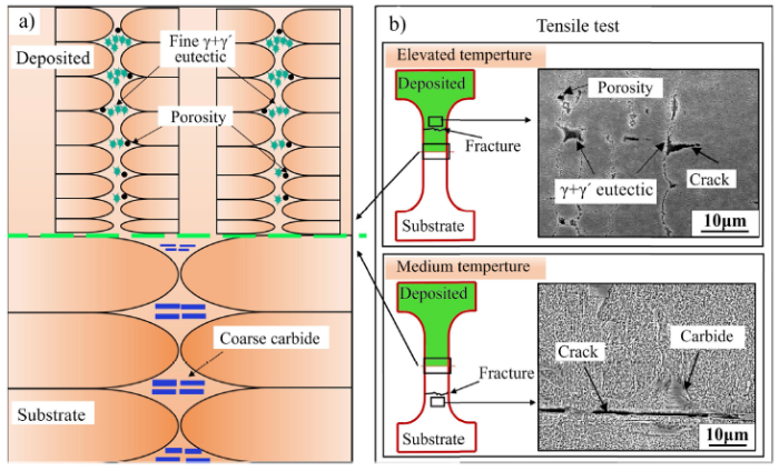
Fig. 15.
Illustration of the fracture mechanism at different temperatures.
It is known that the carbides are a brittle phase, and at moderate temperature tensile test, the coarse MC carbide fragments in the substrate area, inducing the formation of crack. Besides they also provide the crack-propagation path, as shown in Fig. 9(b2). Thus, most of the fracture happens along with them. Therefore, the strength of the substrate will be greatly reduced, and the substrate area is broken preferentially at 660 and 760 °C.
The (γ+γ′) eutectic is a weak phase and seriously deteriorates the elevated-temperature properties, since it tends to break and form microcracks in the interdendritic region at high stress [32]. In addition, the solidification porosity in the deposited area should be taken into account, because the effective cross-sectional area size of the alloy decreases as the increase of porosity. Thus, in the process of the tensile test, the effective stress in the deposited area would be smaller than that in the substrate area. As a result, the tensile properties of the deposited area would be deteriorated by the increase of porosity. Therefore, the deposited area preferentially broke at elevated temperature.
Compared to the substrate area and the deposited area, at the joint area, there are no coarse MC carbides and not so much (γ+γ′) eutectic. In addition, the residual (γ+γ′) eutectic of dendrite in the substrate area dissolves to a great extent and carbides also dissolve partially. So the composition in the joint area is more homogeneous than that in the substrate area, and due to the fast cooling rate during the laser processing, the fine dendritic structure was obtained. Thus, the composition of the joint area at the side of the deposited area is homogeneous, shown in Fig. 13. Therefore, the samples of the repaired SC show good solid solution strengthening in the region of the joint. So the joint area does not fracture at moderate and high temperatures.
5. Conclusions
The crack-free of repaired SC superalloy has been successfully prepared by LMF. The microstructure and tensile property of the repaired SC superalloy samples were characterized to study the microstructural changes during repair and their effects on mechanical properties. The key conclusions can be summarized as below:
(1) The primary dendrite spacing (17.2 μm), secondary arm spacing (3.3 μm), porosity size (3.2 μm) and the γ′ size (39.9 nm in the core dendritic region) in the deposited area were smaller than that in the substrate area (307 μm, 56.8 μm, 15.6 μm and 193 nm, respectively). The volume fraction of porosity in the deposited area (0.19 %) is larger than that in the substrate area (0.11 %);
(2) The cooling rate in the initial cladding layers is fast, and the formation of (γ+γ′) eutectic is inhibited. As the LMF proceeds, the cooling rate decreases gradually at high cladding layers, resulting in an increase of (γ+γ′) eutectic. Due to the existence of the heat affected zone, the (γ+γ′) eutectic dissolves partially, as a result, the (γ+γ′) eutectic at the bottom of the Nth layer is more than that at the top of the N+1th layer;
(3) At moderate temperature, the mechanism of movement of dislocations is mainly a shearing type. At elevated temperature, the main mechanism of movement of dislocations is Orowan bypass. Besides, the irregular dislocation networks can be formed at elevated temperature;
(4) In the moderate temperature tensile test, the fracture mode was cleavage fracture. The coarse carbides, in the substrate area, not only cracked but also provided cracked propagation path, which makes the substrate area break preferentially. In the high-temperature tensile test, the fracture mode was microporous aggregation fracture. The (γ+γ′) eutectic and porosities in the deposited area seriously deteriorated the elevated-temperature properties, thus, the deposited area breaks preferentially. At the joint area, there are no coarse MC carbides like that at the substrate area and not so much (γ+γ′) eutectic as that at the high cladding layers. Thus, the joint area does not fracture at moderate and high temperatures.
Acknowledgments
This work was financially supported by the National Key R&D Program of China (No. 2018YFB1106600), the National Key R&D Program of China (Nos. 2017YFA0700703 and 2018YFB1106000), the National Natural Science Foundation of China (NSFC) (Nos. 51771190, 51671189, U1508213), the National High Technology Research and Development Program (“863”) (No. 2014AA041701) and the Fund of the State Key Laboratory of Solidification Processing in NWPU (No. SKLSP201834).
Reference

AbstractIn order to extend the life cycle of modern single-crystal (SX) high-pressure high-temperature gas turbine blades, repair of cracked or worn parts is of great interest. The success of the repair technique depends critically on a close process control in order to ensure SX repair. Based on solidification theory a process called epitaxial laser metal forming (E-LMF) has been developed. This paper presents the important concepts necessary for any process control for SX repair based on processing maps which relate the expected solidification microstructures and growth morphologies to the processing conditions. These maps are obtained in two steps. Firstly, the relationships between local solidification conditions and the resulting solidification microstructures, i.e. columnar or equiaxed, are formulated. Secondly, the local solidification conditions as a function of the laser processing parameters are calculated with an analytical heat flux model. By a combination of both approaches, processing–microstructure maps are obtained which define processing windows for SX generation and repair by laser deposition.RésuméLa réparation locale d'aubes monocristallines (SX) de turbines à gaz, apportant la possibilité d'augmenter le cycle de vie de ces éléments, est de grand intérêt. Afin de garantir une réparation monocristalline des parties endommagées, un procédé permettant le contrôle des microstructures de solidification est nécessaire. Un tel procédé, epitaxial laser metal forming (E-LMF), a été développé sur la base de théories de solidification. Cet article présente les concepts importants pour le contrôle de la microstructure lors de déposition par laser, et propose des cartes de procédé, reliant la microstructure de solidification et la morphologie de croissance aux paramètres du procédé. Ces cartes sont obtenues en deux étapes. Premièrement, la relation entre les conditions locales de solidification et la microstructure de solidification résultante, i.e. colonnaire ou équiaxe, est établie Deuxièmement, les conditions locales de solidification sont calculées en fonction des paramètres de procédé laser, par un modèle analytique de flux de chaleur. La combinaison des deux approches donne des cartes de microstructure/procédé, permettant l'établissement de fenêtres de procédé pour une réparation monocristalline, par rechargement laser.ZusammenfassungDie Einkristallreparatur von defekten Einkristall-Turbinenschaufeln kann zu einer beträchtlichen Erhöhung der Lebensdauer führen. Der Erfolg der Reparatur hängt kritisch von der Prozesskontrolle ab, durch die das Einkristallgefüge wiederhergestellt wird. Aufgrund von erstarrungstheoretischen Überlegungen wurde ein Prozess entwickelt, der Epitaxiales Laser Metall Formen (E-LMF) genannt wird. Für dieses Verfahren werden Prozesskarten in zwei Stufen ermittelt: (1) Beziehung zwischen den lokalen Erstarrungsbedingungen (G, V) und den Gefügen (gerichtet/globulitisch); (2) Beziehung zwischen lokalen Erstarrungsbedingungen und Laserprozessparametern. Durch Kombination beider Beziehungen konnten Prozess–Gefüge-Karten aufgestellt werden, die es erlauben, eine Einkristallreparatur hoher Qualität zu realisieren.]]>

 WeChat