Influence of particulate morphology on microstructure and tribological properties of cold sprayed A380/Al2O3 composite coatings
Xiang Qiua, b, Naeem ul Haq Tariqc, Lu Qia, b, Jun-Rong Tanga, b, Xin-Yu Cuia, Hao Dua, Ji-Qiang Wanga, *, Tian-Ying Xionga, *
a Institute of Metal Research, Chinese Academy of Sciences, Shenyang 110016, Chinab School of Materials Science and Engineering, University of Science and Technology of China, Shenyang 110016, Chinac Department of Metallurgy and Materials Engineering, Pakistan Institute of Engineering and Applied Sciences, Nilore, Islamabad, Pakistan
Copyright:
2020 Editorial board of Journal of Materials Science & Technology Copyright reserved, Editorial board of Journal of Materials Science & Technology
More
Abstract
In this study, three kinds of A380/Al2O3 composite coatings were prepared by cold spray (CS) using spherical, irregular and spherical + irregular shaped Al2O3 particulates separately mixed in the original A380 alloy powders. The influence of Al2O3 particulates’ morphology on the microstructural characteristics (i.e. retention of Al2O3 content in coatings, coating/matrix interfacial bonding, pore size distribution and morphology etc.) and wear performance of the coatings was investigated by scanning electron microscopy (SEM), X-ray computed tomography (XCT) and 3-D optical profilometry. Results indicated that the spherical Al2O3 shows obvious tamping effect during deposition process. As a result, the interface showed a wavy shape while the matrix and particulates were mechanical interlocked with much improved adhesion. In addition, the porosity of the coating was minimized and the pores exhibited curved spherical structure with reduced dimensions. The irregular Al2O3 particles predominantly displayed the embedding effect together with fragmentation of Al2O3 particulates. Consequently, poor coating/ matrix interfacial bonding, high porosity and the formation of angular-shaped pores were resulted in the coating. Dry sliding wear tests results revealed that the wear resistance of the coating is directly related with the retained content of Al2O3 in the coating. The coating containing irregular Al2O3 particulates displayed superior wear performance with its wear rate one seventh of that of the pure A380 alloy coating. The coating containing both kinds of Al2O3 particulates showed mixed characteristics of above two kinds of Al2O3 composite coatings.
XiangQiu, Naeemul Haq Tariq, LuQi, Jun-RongTang, Xin-YuCui, HaoDu, Ji-QiangWang, Tian-YingXiong. Influence of particulate morphology on microstructure and tribological properties of cold sprayed A380/Al2O3 composite coatings[J]. Journal of Materials Science & Technology, 2020, 44(0): 9-18 https://doi.org/10.1016/j.jmst.2020.01.028
1. Introduction
As an emerging solid-state manufacturing technology, cold spray (CS) has attracted increasing attentions with its unique advantages. During CS process, feedstock particles are mixed with an inert gas stream and are injected to a de Laval type nozzle to form a high velocity jet [[1], [2], [3]]. Subsequently, feedstock particles are supersonically impacted on the substrate and deposition of coating is achieved through severe plastic deformation of the metallic particles [4]. The temperature of the feedstock particles is remained well below their melting point throughout this process [5,6]. As a result, oxidation, phase transformation and other inherent problems of the conventional high-temperature spraying processes could be minimized [7,8]. Therefore, CS is considered as a promising technique to form variety of coatings, additive manufacturing or dimensional damage repairing of engineering components [4,9,10]. It has been reported that CS is technically available to deposit almost all the metallic materials with any thickness (above 50 μm) [4].
In recent years, in order to improve the microstructure of the cold-sprayed metallic coatings and, more importantly, to obtain good specific properties, hard particles such as SiC [11], Al2O3 [[12], [13], [14]], WC [15] and TiN [8] etc. were added in the feedstock powder to fabricate metal matrix composite (MMC) coatings. For example, Spencer et al. [12] deposited Al2O3 reinforced stainless steel matrix composite coatings on AZ91 Mg substrate with 25, 50 and 75 vol.% of Al2O3. The results showed that the largest addition of angular Al2O3 particulates resulted in slightly increased coating hardness and an order of magnitude reduction in the wear rate against a hardened steel counter material. Similar results were reported by Melendez et al. [16] for WC/ nickel composite coatings wherein the wear resistance of the composite coatings was significantly increased with increasing volume fraction of WC in the feedstock. Li et al. [8] fabricated TiN/Al2319 composite coatings by CS and studied the coating characteristics. Quite interestingly, the TiN particles were uniformly dispersed in the coating with even higher volume fraction (~38.7 vol.%) than that in the feedstock (~32.7 vol.%). The in-depth analysis of the coating revealed that the angular TiN particles played a pinning role in the matrix and resulted in reduced level of porosity as well as increased cohesive strength in the composite coating when compared with pure Al2319 alloy coating. Quite recently, a new term “in-situ micro-forging effect” was coined for the CS process wherein large sized (100-200 μm) spherical (hard) particles were added to the metallic feedstock powder to achieve dense deposits of Inconel 718 alloy [17]. The porosity of the coating was gradually reduced while inter-particle bonding was improved due to enhanced in-situ micro-forging effect. Consequently, deposits with much improved mechanical properties could be obtained. The above literatures suggest that CS is a promising process to fabricate variety of MMCs coatings for variety engineering applications. However, more in-depth studies are required to understand the effect of morphology of hard particles in minimizing pores inside the coating. To date, there is no study available in the open literature that is mainly focused in studying the effect of particulates morphology on size, shape and distribution of the pores inside the coating.
The A380 aluminum alloy (Al-Si-Cu alloy) is commonly used in the industry for various engineering applications. It is widely used in the automobile industry to manufacture cylinder heads and engine blocks due to its light weight, high strength and excellent wear resistance [[18], [19], [20], [21]]. In our previous work [22], we successfully achieved a dense coating of A380 aluminum alloy by adding spherical Al2O3 particulates to the original A380 alloy powder and subsequently studied its microstructure and properties. The results revealed that the spherical Al2O3 has a strong tamping effect on the coating characteristics. Addition of 10 wt% spherical Al2O3 particulates to the metallic feedstock powder resulted in reduction of the porosity of the coating to one-quarter while the surface roughness and wear rate were decreased to one-half. However, the deposition efficiency of Al2O3 is very low (~1 vol.%), which limits further improvement of properties of the coating. The above literature further revealed that the Al2O3 particulates with irregular morphology is much easier to be deposited, thus the hardness and wear resistance of the coatings could be further improved. However, it is also reported that irregular hard particulates are more susceptible to fragmentation during deposition process thus resulting in deteriorated microstructure of the coating [23].
Therefore, in order to achieve an A380 alloy coating with excellent properties like high density, high wear resistance and high hardness etc., three kinds of A380/ Al2O3 composite coatings were prepared by adding spherical, irregular and spherical + irregular shaped Al2O3 particulates in the original A380 alloy powder. The influence of different Al2O3 particulates on the microstructure of the coatings was studied in detail by SEM. Moreover, for the first time, corresponding change in pores morphology, size and distribution in the coating was systematically studied by X-ray computed tomography (XCT). Finally, dry friction tests were carried out on different coatings and effect of different Al2O3 particulates on the tribological properties of the coating was studied.
2. Experimental
2.1. Sample preparation
The as-received gas-atomized A380 alloy powders (Al-8.74Si-3.30Cu-0.35Zn- 0.27Fe-0.24 Mn) and Al2O3 powders with different morphology (spherical and irregular) were used as the matrix and the reinforcement materials, respectively. Detailed information on these raw materials powders can be found elsewhere [24]. Three batches of the composite feedstock powder were prepared by mechanically mixing A380 alloy powder with 20 wt% spherical Al2O3 powder, 20 wt% irregular Al2O3 powder, 10 wt% spherical Al2O3 + 10 wt% irregular Al2O3 powder and the corresponding coatings were designated as (S) composite coating, (I) composite coating and (S + I) composite coating, respectively. Each batch of the feedstock powder was mixed with ZrO2 balls (3 mm in diameter) and mechanically blended for 8 h in a jar mill (rotated with a slow speed, i.e. 75 rpm) to achieve uniform blending. After blending, ZrO2 balls were sieved out from the feedstock. Unlike the ball milling or mechanical alloying process, the energy input during this process is very low. Therefore, the blending process did not result in any significant change in the morphology or the size distribution of the starting powders. Commercially available 6061Al alloy substrate was prepared by initially cleaning with acetone and subsequently sandblasting using SiO2 girt to remove the oxide layer.
A high-pressure PCS-1000 cold spray system (Plasma Giken Co., Ltd., Japan) was used for powder deposition. Nitrogen was used as the carrier gas as well as the propelling gas. During spraying process, the temperature and gas pressure were kept at ~500 °C and 4 MPa, respectively. The nozzle traverse speed was set as 100 mm/s and a constant stand-off distance of 30 mm was maintained throughout the deposition process. The powder feed rate was fixed at 25 ± 5 g/min for all experiments. The final thickness of the cold sprayed pure A380 alloy coating and (S), (I), (S + I) composite coatings was about 1.5 mm.
2.2. Microstructural characterization
The microstructure of the coatings was examined using scanning electron microscopy (SEM, Zeiss Merlin Compact, Germany) and optical microscopy (OM, Zeiss Observer, Germany). All specimens were hot mounted followed by grinding and polishing using standard metallographic procedures. In order to estimate the Al2O3 content in the coatings, metallographic image analysis software (Image J) was used. For this purpose, at least 10 cross sectional images (at 500× magnification) were selected and the total measurement area was over 300,000 μm2.
In order to precisely study the size, morphology and distribution of the pores in different coatings, samples were examined by using 3-dimensional X-ray computed tomography (XCT, Xradia Versa XRM-500, Carl Zeiss X-ray Microscopy Inc., USA) equipment. For XCT measurement, cylindrical samples with the dimensions of Φ 0.6 mm × 4 mm were placed on a 360° rotation stage in front of the X-ray source. For all samples, the acceleration voltage was set to 50 kV. In order to analyze pores characteristics, cubic volume of 500 μm × 500 μm × 900 μm was selected from the scanned sample with a voxel size of 1.3 μm × 1.3 μm × 1.3 μm. The three-dimensional volume was reconstructed by the Avizo software (V7.1, Visualization Sciences Group, Bordeaux, France). The volume of residual pores was calculated for all samples, whereas, the equivalent diameter (d) of the pores is estimated by equating a single pore to an equal volume of a sphere, i.e., V (pore)=V (sphere)=πd3/6.
Microhardness measurements were performed using a Vickers microhardness tester (AMH43, Leco, USA) under a load of 300 gf with 15 s holding time. For hardness measurement, ten equally spaced positions in the middle of the cross section of the coating were selected and the values were averaged out.
Adhesion strength of different coatings (with the substrate) was evaluated by performing a series of tensile (pull-off) adhesion tests [25,26] on INSTRON 5848 tensile test machine. All tests were performed according to the ASTM C633 standard. Adhesion test specimens were cut into cylindrical shape with dimensions of Φ20 mm × 3 mm. Both sides of the specimen were ground and glued with the holders using E-7 epoxy glue. The maximum bond strength of E-7 epoxy glue is ~70 MPa. The tensile adhesion test was performed using cross-head speed of 0.5 mm/min. The adhesion strength is defined as; the maximum load (on load-displacement curve) divided by coating/substrate interfacial area. For each coating, three specimens were tested to ensure reproducibility of the results.
2.3. Wear test
Dry sliding wear tests on the coatings were carried out at room temperature using ball-on-disc system. Before wear test, the coatings were ground and polished to the final step by using 0.5 μm diamond suspension in an automatic polisher. The counter material for wear test was an Al2O3 ball with the diameter of 6 mm. The wear tests were conducted under normal load of 3 N. During wear test, coating samples were fixed on the holder and the rotation speed was set to 180 rpm. The wear track was a circle with a diameter of 6 mm. The wear time was kept to 10 min and the corresponding wear length was fixed to 37.7 m. The friction coefficient and the sliding distance were dynamically recorded in the computer program. The wear rate was defined as the worn volume per unit of sliding distance. For each sample, more than 10 different positions of the worn trace were selected to calculate the cross-sectional areas. Wear surface topography were analyzed by SEM and a non-contact optical profilometry (3D Micro XAM, KLA, USA).
3. Results and discussion
Fig. 1 shows cross-sectional SEM image of the coatings at two different magnifications. For pure A380 coating, triangular or narrow pores can be clearly noticed at the boundary of the deformed particles (Fig. 1(b)). These are the typical cold spray defects caused by insufficient deformation of metallic particles. For composite coatings, it can be observed that the coatings generally exhibit dense microstructure with few micro pores. The (S) composite coating shows the lowest porosity value because of intense tamping effect generated by the spherical hard Al2O3 particulates. In contrast, the (I) and the (S + I) composite coatings show relatively high porosity values (less tamping effect) due to the angular morphology of irregular Al2O3 particulates and the fragmentation phenomenon. The Al2O3 particulates are uniformly distributed in the composite coatings. The morphology of Al2O3 has a great influence on its deposition efficiency. The deposition efficiency of Al2O3 with irregular morphology is much higher than that of the spherical Al2O3. The content of Al2O3, as estimated by Image J software, in (S), (I) and (S + I) composite coating is 2.14 % ± 0.69 %, 13.22 % ± 1.34 % and 6.78 % ± 1.54 %, respectively. The results seem quite reasonable. Spherical Al2O3 particles are difficult to penetrate in the coatings. To achieve higher penetration, they must either break into the pieces to obtain necessary angularity or get trapped between incoming A380 particles. In case of irregular Al2O3 particles, the polygonal structure ensures higher probability of embedding over spherical Al2O3 particles and helps to lock the particles in the A380 coatings upon impact. For all composite coatings, the magnified view of a randomly selected A380/Al2O3 interface is provided as the insert in Fig. 1. For the (S) composite coating, sufficiently deformed A380 splats and Al2O3 particles exhibit good bonding at most of the interfacial regions without any crack. In contrast, un-bonded interfacial regions can be clearly identified in the (I) composite coating which is attributed to the lack of sufficient tamping, as shown by the black arrow in Fig. 1(f). Consequently, the properties of the material are deteriorated. The A380/Al2O3 interfaces in the (S + I) composite coating exhibit a combination of above two bonding characteristics.
Fig. 1. Representative cross-sectional SEM micrographs of different samples at different magnifications: (a, b) pure A380 alloy coating; (c, d) (S) composite coating; (e, f) (I) composite coating; (g, h) (S + I) composite coating. The insets show randomly selected A380/Al2O3 interface.
It is worthy to note that the addition of Al2O3 particulates has a significant influence on the coating/substrate interfacial characteristics. The coating/substrate interface of A380 coating exhibits more or less uneven morphology, which suggests that both of them have experienced certain degree of deformation when the particles impact the substrate and the bonding between the coating and the matrix is good. The adhesion strength of the coating was measured to be 33.6 MPa (Table 1). For (S) composite coating, the interface shows a wavy shape while the matrix and particulates are mechanically interlocked to result in much improved adhesion (Fig. 1(d)). This is quite evident in Table 1, wherein (S) composite coating shows the highest adhesion strength among all the coatings. In (S) composite coating, fracture took place from the glue, indicating that the strength of the coating/substrate interfacial bonding is much higher than the measured average value (59.9 MPa). In contrast, the coating/substrate interface of (I) composite coating is relatively flat with some angular Al2O3 particulates penetrated in the substrate. The adhesion strength of (I) coating is higher than that of pure A380 coating (33.6 MPa) but lower than that of (S) composite coating (Table 1). This indicates that irregular Al2O3 particles have a limited tamping effect. For (S + I) composite coating, the interface exhibits similar characteristics like (S) composite coating with reduced penetration of Al2O3 fragments. The adhesion strength of the coating (49.8 MPa) is only lower than that of the (S) composite coating which is attributed to the adequate tamping and load bearing effects induced by both kinds of Al2O3 particles.
Table 1
Table 1 Adhesion strength of the pure A380 alloy and composite coatings.
Fig. 2 shows distribution of interior pores conducted by XCT. Compared with commonly used OM observation, XCT investigation provides three dimensional distributions of the pores as well as their morphology [27]. The pores are color coded according to the distributions of the equivalent diameters. For clarity, we removed the matrix phase as well as the particulate phase from the entire volume. It can be seen that the pores are relatively uniformly distributed in the observation cube. The porosity value was obtained by calculating the volume ratio between the total detected pores and the cube with dimensions of 0.5 mm × 0.5 mm × 0.9 mm.The results of porosity for different samples are compared in Fig. 3(a). Moreover, the distributions of equivalent diameter of the pores within the observation cube are also presented in Fig. 3(b). Pure A380 coating shows the highest porosity value (~1.4 %) among all these four different coatings, indicating insufficient deformation of the A380 alloy particles during deposition. This implies that the pure A380 alloy coating has high defect density at the junction of the particles. The equivalent diameter of the pores is between 5-40 μm and the majority of the pores have an equivalent diameter of 5-15 μm (Fig. 3(b)). Since the addition of spherical Al2O3 can significantly densify the coating, the porosity value is sharply decreased to 0.6 % in (S) composite coating. This is quite consistent with the cross-sectional image shown in Fig. 1. Moreover, the equivalent diameter distribution of the pores in (S) coating is remarkably different from that of A380 alloy coating. The equivalent diameter of some pores is less than 5 μm, indicating better deposition behavior of the particles with higher degree of plastic deformation. As a result, the size of the pores at the splat boundaries is reduced, which further verifies the tamping effect of spherical Al2O3. The porosity and equivalent pore diameter distribution for (I) and (S + I) composite coatings maps are similar to those of the pure A380 coating. This suggests that the addition of irregular Al2O3 has a limited effect in minimizing the pores due to its weak tamping effect and undesired fragmentation process. When two kinds of Al2O3 particulates were simultaneously deposited in the coating, the embedding effect of the irregular Al2O3 particulates significantly weakened the tamping effect (of the spherical Al2O3 particulates) which in turn adversely affected the coating quality.
Fig. 2. 3D-reconstruction of the pores within the different samples: (a) pure A380 alloy coating; (b) (S) composite coating; (c) (I) composite coating; (d) (S + I) composite coating.
Fig. 3. (a) Porosity variation and (b) distribution of equivalent diameter of the pores within different coating samples.
In order to better understand the effect of Al2O3 addition on the morphology of the pores, typical medium-sized pores (represented in yellow and green colors in the map) were selected from the observation cube, as shown in Fig. 4. For A380 alloy coating, the pores exhibit a variety of different morphologies, most of which are dominated by staggered, complex and curved structures. This indicates that the A380 alloy particles are not deformed sufficiently and the coating is composed of large number of different kinds of defects. The pores which exhibit extruded spherical surface features seem to be formed at the boundary of two deformed elliptical or elongated A380 alloy particles. The pores with staggered and complex structures seemingly formed at the intersection of the boundaries of severely deformed splats. For (S) composite coating, the pores mainly exhibit the curved spherical structure while the ratio of the complex-structured pores is decreased significantly when compared with that of the pure A380 alloy coating. This suggests that the tamping effect of spherical Al2O3 is quite remarkable, and most of the A380 particles are elongated strips with sufficient deformation. It is interesting to note that for (I) composite coating, in addition to the above mentioned two kinds of defects, pores with angular shape were also observed (Fig. 4(f)), which is considered to be the outcome of the cracks generated inside the Al2O3 particles during fragmentation. The (S + I) composite coating consists of pores with all three morphologies as shown in Fig. 4(g-h), which indicates that the tamping, embedding and fragmentation of Al2O3 particulates occur simultaneously in the coating during deposition process.
Fig. 4. Typical medium-sized pores in different samples: (a, b) pure A380 alloy coating; (c, d) (S) composite coating; (e, f) (I) composite coating; (g, h) (S + I) composite coating.
Fig. 5 shows the variation of mircohardness values of the coatings and it can be observed that the hardness values demonstrate the similar trend as that of the deposition efficiency of the Al2O3 particulates. Pure A380 alloy coating shows the lowest hardness value (~ 119 HV0.3) due to the absence of tamping effect and high defect density. The (S) composite coating possesses a 10 % higher microhardness than that of the pure A380 coating. Since the amount of Al2O3 in the coating is very low, the significantly reduced porosity of the coating and the increased degree of work hardening, as a result of tamping effect of the spherical Al2O3 particulates, are considered to be the main reasons contributing to the increase in the hardness. For (I) and (S + I) composite coatings, the amount of retained Al2O3 particulates in the coating is relatively higher and the indenter is likely to be pressed against the hard Al2O3 particles during hardness test. Consequently, the coatings possess high load bearing capacity.
Fig. 5. The microhardness values of different coatings.
The effect of addition of Al2O3 particulates (with different morphologies) on the coating microstructures is summarized as follows. Spherical Al2O3 particulates showed more dominant tamping effect by hitting the substrate and the pre-deposited layer at high speed. As a result, the substrate with original flat surface, exhibited rugged shape characteristics due to the severe impact of spherical Al2O3 particulates, which facilitated high interfacial contact area and efficient mechanical interlocking of A380 splats with the substrate. Moreover, according to Getu’s modeling and experimental work [28], the curvature of the spherical particle boundary is almost constant, therefore, the elastic rebound forces perpendicular to the impact direction is high enough to prevent the embedding of the particles. These particles are only embedded if the spherical particle hits to a depth which is much greater than its radius and subsequently it is covered by the in-coming matrix particles [28,29]. Therefore, the amount of Al2O3 particulates retained in the coating is low and most of the spherical particles rebound after transferring part of their energy to the pre-deposited A380 particles. This energy is consumed to instigate secondary plastic deformation of the matrix phase. As a result, the compactness of the deposit and hardening of the impacted surface are enhanced due to the tamping effect of spherical Al2O3 particulates, as evidenced by improved inter splat bonding (curved-structure pores in Fig. 4), reduced porosity (Fig. 3) and increased hardness (Fig. 5) in (S) composite coating.
In contrast, the irregular Al2O3 particles show weaker tamping effect but is dominated by the embedding effect. Based on Getu et al.’s finding [28], the direction of normal and tangential components of elastic rebound forces remain constant because of sharp corners and the flat sides of Al2O3 particles. The particles, with angular morphology, are easy to be embedded rather than rebound as long as the static friction forces between particle and substrate materials remains sufficiently high. Therefore, more irregular Al2O3 particulates retained in the deposit (~13 vol.%), which act as a load bearing phase in the composite coating with much higher hardness (Fig. 5). The embedding phenomenon of the irregular Al2O3 particulates results in secondary plastic deformation in whole A380 matrix. However, it cannot effectively compact the deposits although sharp corners and the flat sides of Al2O3 particles induce a certain tamping effect on the matrix. Therefore, the flat coating/substrate interface, poor adhesion strength, poor A380/Al2O3 interfacial bonding and complex-structured pores are resulted.
The wear rates of pure A380 coating and composite coatings after dry sliding test are shown in Fig. 6 while Fig. 7 presents the 3D morphologies of the wear track of the corresponding coatings. It can be observed that increased Al2O3 content results in improved wear resistance of the coatings. Pure A380 coating shows the highest wear rate among all the coatings. Correspondingly, the depth and width of the wear track (more than 20 μm and 1200 μm, respectively) are the largest among all the coatings, as shown in Fig. 7(a). Moreover, the addition of both types of Al2O3 particulates can alter the wear resistance of the coatings viz. the wear resistance of coatings increases with the increase of Al2O3 content in coatings. The wear rate of the (S) composite coating is about 6.5 × 10⁻³ mm3/m, which is more than 30 % lower than that of the pure A380 coating. The (I) composite coating shows the best wear resistance with its wear rate (1.4 × 10⁻³ mm3/m) only one seventh of that of pure A380 coating. It can also be observed in Fig. 7(c) that the depth and the width of the wear track are significantly reduced to less than 10 μm and 800 μm, respectively. The wear rate of the (S + I) composite coating is about 4.2 × 10⁻³ mm3/m, which is higher than that of the (I) composite coating, but much lower than that of the (S) composite coating.
Fig. 7. 3D morphologies of wear tracks of different coatings: (a) pure A380 alloy coating; (b) (S) composite coating; (c) (I) composite coating; (d) (S + I) composite coating.
The wear performance of different cold sprayed composite coatings is resulted through the combined effect of various factors, i.e. (i) retained content (volume fraction) of Al2O3 in the coatings, (ii) porosity, and (iii) cohesion between A380/A380 splats and A380/Al2O3 interface. As the content of the hard phase increases, wear loss of the composite samples decreases [30]. Moreover, it results in intense tamping action which in turn reduces porosity and improves A380/A380 & A380/Al2O3 interfacial bonding. Hard Al2O3 particles (with good interfacial bonding with the matrix) provide a great amount of resistance to the micro-cutting action of the rubbing abrasive. Consequently, the rate, at which surface material is removed, is significantly reduced. Further, Al2O3 particulates (with good interfacial bonding with the matrix) act as load bearing phase and limit the tendency of forming mixed mechanical layer (MML) on the composite surface [31]. In short, the wear performance of the composite coating is highly depended upon its porosity level and volume fraction of well bonded/locked hard phase. The phenomenon of increase in wear resistance of the coatings with increasing Al2O3 content can be explained by the inverse rule of mixtures or equal wear theory which is typically used to predict the lower bound for the wear rate of a composite material. This theory suggests that the hard particles completely reinforce the composite and each entity of it will wear at a rate as if it were a homogeneous material [16]. The equation of this theory is presented as follows:
where W and V are the wear rate and volume fraction respectively and the subscripts c, m and r correspond to the composite, matrix and reinforcement, respectively. This formula was modified by using a contribution coefficient parameter (C) and taking the fact into account that cracks at the reinforcement/ matrix interface would significantly affect the wear rate of the composite as provided as follows [32]:
It is hard to accurately measure the wear rate of the composite by above equation as no study has been conducted to evaluate the wear rate of the cold sprayed Al2O3 (Wr). However, this formula can be used to obtain the relationship between wear resistance of composites and Al2O3 contents. Assuming that the cold sprayed composite is dense with negligibly low porosity value and “Vm” can be replaced by “1- Vr”, then Eq. (2) can be rewritten as follows:
From Eq. (3) we can clearly notice that the wear rates of the composite and hard phase volume fraction are inversely proportional. The wear rate of the composite can be minimized by increasing the content of the hard particulates, which is consistent with the experimental result presented in Fig. 6.
Fig. 8 shows representative worn surfaces of all four coatings. For pure A380 alloy coatings, the flaked off (loose) lamellar debris and some huge grooves can be found on the wear track, indicating that the coating was worn plastically because of the repeated loading. It is widely accepted that for ductile materials, plastic deformation is the main approach for material removal during wear process [16]. This is also consistent with the 3-D wear track profile shown in Fig. 7(a) displaying plowing and extrusion features of the worn material outside the wear track. The above results indicate that the wear mechanism in pure A380 alloy coating is adhesive wear. Further evidence of adhesive wear was revealed by examining the worn Al2O3 counter material. The A380 alloy debris was found to stick to the Al2O3 ball which appears to be intact. This suggests that material transfer has taken place from the softer coating to the harder counter material, which is the typical characteristic of adhesive wear.
Fig. 8. SEM morphologies of wear tracks of different coatings: (a) pure A380 alloy coating; (b) (S) composite coating; (c) (I) composite coating; (d) (S + I) composite coating.
The worn surface of (S) composite coating also shows some evidence of adhesive wear, which is characterized by the smeared surface with layered structure. This can also be proved by the 3-D wear track profile wherein the trace of smearing is obvious as shown in Fig. 7(b). Compared with pure A380 coating, debris of the (S) composite coating seems denser and smoother with almost no debris flaked off the contact surface. This is attributed to the dense coating structure resulted from intense tamping effect of spherical Al2O3. Moreover, the brim-like shapes (marked by blue arrow) are observed on the worn surface which was assumed to be formed by the higher degree of deformation of the coating surface (parallel to the sliding direction) than that of the subsurface [8]. This also suggests that the adhesion between the coating material and the Al2O3 counter ball is a dominant factor for the wear behavior of the (S) composite coating.
The worn surface of (I) composite coating shows signs of smearing and adhesive wear as observed in (S) composite coatings, however, there is also some evidence of abrasive wear. Some micro-grooves are formed due to micro-cutting effect, as shown in Fig. 8(c). Moreover, debris distributed on the worn surface with irregular morphology, which also suggests that the surface layer involved in the wear process underwent a decreased parallel deformation due to the embedding effect of the irregular Al2O3 particulates [8]. The Al2O3 and Al2O3 fragments retained in the coating are easy to be pulled out and these particles may contribute to a third-body abrasion during the sliding process.
The wear track of the (S + I) composite coating shows a combined surface characteristic of adhesive wear and abrasive wear. Smeared surface with layered structure and the brim-like shapes can also be observed but the worn surface appeared to be denser and smoother than those observed in other coatings. During repeated plastic deformation, the degree of hardening of the debris increases and some lamellar debris are peeled off, leaving the original pits on the worn surface, as marked by yellow arrow in Fig. 8(d). This may attribute to the higher wear rate of the (S + I) coating compared with (I) composite coating. Moreover, some debris may act as a third body during sliding process which result in scratching process, as evident in Fig. 8(d).
Fig. 9 shows the variation of coefficients of friction (COF) with sliding cycles for pure A380 alloy and composite coatings. It can be seen that all the samples experience a fluctuation at the early stage of the friction process with the increase in COF to a peak value and then stabilization is reached after the sliding cycles of 400. Pure A380 alloy coating exhibits the higher COF against the counter ball compared with the composite samples because of the higher contact area between the ball and the wear track (as evident in Fig. 7(a)) and resulted higher frictional force. As analyzed from the wear track shown in Fig. 8, (S) and (S + I) composite coatings show similar frictional behavior and their COF against the counter ball are almost the same. (I) composite coating shows superior wear resistance featured by the lowest wear rate and COF values. Due to the highest Al2O3 content in the coating, abrasive wear and three-body wear occur during friction. The contact area between the counter ball and the coating is minimized by the Al2O3 fragments remained in the wear track and the debris produced by three-body wear process. This is also consistent with the 3-D wear track analysis presented in Fig. 7(c) wherein the wear track of (I) composite coating is the shallowest and the narrowest among all the coatings.
Fig. 9. Friction coefficient vs. number of sliding cycles.
4. Conclusions
(1) The (S) composite coating exhibits the lowest porosity and best substrate/ coating interfacial bonding among all the coatings due to intense tamping effect of the spherical Al2O3 particles. For (I) composite coating, the Al2O3 particulates were easily deposited but also fragmented, which resulted in poor interfacial bonding and relatively high porosity. The structure of (S + I) coating is characterized by the combination of (S) and (I) coatings with moderate Al2O3 content and interfacial bonding.
(2) Based upon XCT results, the equivalent diameter of the pores in (S) composite coating is smaller than that of A380, (I) and (S + I) coatings due to efficient tamping effect. The pores mainly exhibit staggered and the curved spherical structure in A380 alloy coating and (S) composite coating, respectively. For (I) composite coating, in addition to the above mentioned two kinds of defects, pores with angular shape were also observed because of the fragmentation of Al2O3 particulates. The (S + I) composite coating consists of pores with all three kinds of morphologies.
(3) Dry sliding wear test results revealed that the increased Al2O3 content in the coating results in improved wear resistance. The (I) composite coating shows the best wear resistance with its wear rate (1.4 × 10⁻³ mm3/m) only one seventh of that of pure A380 alloy coating. Smeared surface was noticed on worn surface of all the coatings, indicating the adhesive wear mechanism. The (I) and (S + I) composite coatings show a combined surface structure characteristic of adhesive wear and abrasive wear with sporadic events of micro-grooves.
Acknowledgment
This work was financially supported by the National Natural Science Foundation of China (Nos. 51671205 and 51801217).
AbstractCold gas spraying is a relatively new coating process by which coatings can be produced without significant heating of the sprayed powder. In contrast to the well-known thermal spray processes such as flame, arc, and plasma spraying, in cold spraying there is no melting of particles prior to impact on the substrate. The adhesion of particles in this process is due solely to their kinetic energy upon impact. Experimental investigations show that successful bonding is achieved only above a critical particle velocity, whose value depends on the temperature and the thermomechanical properties of the sprayed material. This paper supplies a hypothesis for the bonding of particles in cold gas spraying, by making use of numerical modelling of the deformation during particle impact. The results of modelling are assessed with respect to the experimentally evaluated critical velocities, impact morphologies and strengths of coatings. The analysis demonstrates that bonding can be attributed to adiabatic shear instabilities which occur at the particle surface at or beyond the critical velocity. On the basis of this criterion, critical velocities can be predicted and used to optimise process parameters for various materials.]]>
[6]
R.Jenkins, S.Yin, B.Aldwell, M.Meyer, R.Lupoi, J. Mater. Sci. Technol.35(2019) 427-431.
SiC particle reinforced A15056 composite coatings were prepared by cold spraying using initial powders containing 15, 30, 45 and 60 vol.% SiC. Effects of SiC content in the coating on microstructure, mechanical property and wear behavior of the coatings were studied. Experimental results show that the SiC particles in the coating improve the deformation of A15056 particles and also increase the hardness of the coating. The cohesion strength of the composite coatings firstly increases and then decreases with the increase of SiC content in the coatings as a result of comprehensive effects of the SiC particles on improving the deformation of A15056 particles and on reducing the effective contact area between the A15056 particles. Finally, tribological tests show that the SiC particle and its content in the coatings would greatly influence the tribological behavior of the coatings. The worn tracks suggest that the delaminating wear is the wear mechanism of the A15056 and A15056/SiCp coatings at the present tribological condition. (C) 2013 Elsevier B.V.
... As an emerging solid-state manufacturing technology, cold spray (CS) has attracted increasing attentions with its unique advantages. During CS process, feedstock particles are mixed with an inert gas stream and are injected to a de Laval type nozzle to form a high velocity jet [[1], [2], [3]]. Subsequently, feedstock particles are supersonically impacted on the substrate and deposition of coating is achieved through severe plastic deformation of the metallic particles [4]. The temperature of the feedstock particles is remained well below their melting point throughout this process [5,6]. As a result, oxidation, phase transformation and other inherent problems of the conventional high-temperature spraying processes could be minimized [7,8]. Therefore, CS is considered as a promising technique to form variety of coatings, additive manufacturing or dimensional damage repairing of engineering components [4,9,10]. It has been reported that CS is technically available to deposit almost all the metallic materials with any thickness (above 50 μm) [4]. ...
1
2019
... As an emerging solid-state manufacturing technology, cold spray (CS) has attracted increasing attentions with its unique advantages. During CS process, feedstock particles are mixed with an inert gas stream and are injected to a de Laval type nozzle to form a high velocity jet [[1], [2], [3]]. Subsequently, feedstock particles are supersonically impacted on the substrate and deposition of coating is achieved through severe plastic deformation of the metallic particles [4]. The temperature of the feedstock particles is remained well below their melting point throughout this process [5,6]. As a result, oxidation, phase transformation and other inherent problems of the conventional high-temperature spraying processes could be minimized [7,8]. Therefore, CS is considered as a promising technique to form variety of coatings, additive manufacturing or dimensional damage repairing of engineering components [4,9,10]. It has been reported that CS is technically available to deposit almost all the metallic materials with any thickness (above 50 μm) [4]. ...
1
2018
... As an emerging solid-state manufacturing technology, cold spray (CS) has attracted increasing attentions with its unique advantages. During CS process, feedstock particles are mixed with an inert gas stream and are injected to a de Laval type nozzle to form a high velocity jet [[1], [2], [3]]. Subsequently, feedstock particles are supersonically impacted on the substrate and deposition of coating is achieved through severe plastic deformation of the metallic particles [4]. The temperature of the feedstock particles is remained well below their melting point throughout this process [5,6]. As a result, oxidation, phase transformation and other inherent problems of the conventional high-temperature spraying processes could be minimized [7,8]. Therefore, CS is considered as a promising technique to form variety of coatings, additive manufacturing or dimensional damage repairing of engineering components [4,9,10]. It has been reported that CS is technically available to deposit almost all the metallic materials with any thickness (above 50 μm) [4]. ...
3
2016
... As an emerging solid-state manufacturing technology, cold spray (CS) has attracted increasing attentions with its unique advantages. During CS process, feedstock particles are mixed with an inert gas stream and are injected to a de Laval type nozzle to form a high velocity jet [[1], [2], [3]]. Subsequently, feedstock particles are supersonically impacted on the substrate and deposition of coating is achieved through severe plastic deformation of the metallic particles [4]. The temperature of the feedstock particles is remained well below their melting point throughout this process [5,6]. As a result, oxidation, phase transformation and other inherent problems of the conventional high-temperature spraying processes could be minimized [7,8]. Therefore, CS is considered as a promising technique to form variety of coatings, additive manufacturing or dimensional damage repairing of engineering components [4,9,10]. It has been reported that CS is technically available to deposit almost all the metallic materials with any thickness (above 50 μm) [4]. ...
... ]. Therefore, CS is considered as a promising technique to form variety of coatings, additive manufacturing or dimensional damage repairing of engineering components [4,9,10]. It has been reported that CS is technically available to deposit almost all the metallic materials with any thickness (above 50 μm) [4]. ...
... ]. It has been reported that CS is technically available to deposit almost all the metallic materials with any thickness (above 50 μm) [4]. ...
1
2003
... As an emerging solid-state manufacturing technology, cold spray (CS) has attracted increasing attentions with its unique advantages. During CS process, feedstock particles are mixed with an inert gas stream and are injected to a de Laval type nozzle to form a high velocity jet [[1], [2], [3]]. Subsequently, feedstock particles are supersonically impacted on the substrate and deposition of coating is achieved through severe plastic deformation of the metallic particles [4]. The temperature of the feedstock particles is remained well below their melting point throughout this process [5,6]. As a result, oxidation, phase transformation and other inherent problems of the conventional high-temperature spraying processes could be minimized [7,8]. Therefore, CS is considered as a promising technique to form variety of coatings, additive manufacturing or dimensional damage repairing of engineering components [4,9,10]. It has been reported that CS is technically available to deposit almost all the metallic materials with any thickness (above 50 μm) [4]. ...
1
2019
... As an emerging solid-state manufacturing technology, cold spray (CS) has attracted increasing attentions with its unique advantages. During CS process, feedstock particles are mixed with an inert gas stream and are injected to a de Laval type nozzle to form a high velocity jet [[1], [2], [3]]. Subsequently, feedstock particles are supersonically impacted on the substrate and deposition of coating is achieved through severe plastic deformation of the metallic particles [4]. The temperature of the feedstock particles is remained well below their melting point throughout this process [5,6]. As a result, oxidation, phase transformation and other inherent problems of the conventional high-temperature spraying processes could be minimized [7,8]. Therefore, CS is considered as a promising technique to form variety of coatings, additive manufacturing or dimensional damage repairing of engineering components [4,9,10]. It has been reported that CS is technically available to deposit almost all the metallic materials with any thickness (above 50 μm) [4]. ...
1
2018
... As an emerging solid-state manufacturing technology, cold spray (CS) has attracted increasing attentions with its unique advantages. During CS process, feedstock particles are mixed with an inert gas stream and are injected to a de Laval type nozzle to form a high velocity jet [[1], [2], [3]]. Subsequently, feedstock particles are supersonically impacted on the substrate and deposition of coating is achieved through severe plastic deformation of the metallic particles [4]. The temperature of the feedstock particles is remained well below their melting point throughout this process [5,6]. As a result, oxidation, phase transformation and other inherent problems of the conventional high-temperature spraying processes could be minimized [7,8]. Therefore, CS is considered as a promising technique to form variety of coatings, additive manufacturing or dimensional damage repairing of engineering components [4,9,10]. It has been reported that CS is technically available to deposit almost all the metallic materials with any thickness (above 50 μm) [4]. ...
5
2008
... As an emerging solid-state manufacturing technology, cold spray (CS) has attracted increasing attentions with its unique advantages. During CS process, feedstock particles are mixed with an inert gas stream and are injected to a de Laval type nozzle to form a high velocity jet [[1], [2], [3]]. Subsequently, feedstock particles are supersonically impacted on the substrate and deposition of coating is achieved through severe plastic deformation of the metallic particles [4]. The temperature of the feedstock particles is remained well below their melting point throughout this process [5,6]. As a result, oxidation, phase transformation and other inherent problems of the conventional high-temperature spraying processes could be minimized [7,8]. Therefore, CS is considered as a promising technique to form variety of coatings, additive manufacturing or dimensional damage repairing of engineering components [4,9,10]. It has been reported that CS is technically available to deposit almost all the metallic materials with any thickness (above 50 μm) [4]. ...
... In recent years, in order to improve the microstructure of the cold-sprayed metallic coatings and, more importantly, to obtain good specific properties, hard particles such as SiC [11], Al2O3 [[12], [13], [14]], WC [15] and TiN [8] etc. were added in the feedstock powder to fabricate metal matrix composite (MMC) coatings. For example, Spencer et al. [12] deposited Al2O3 reinforced stainless steel matrix composite coatings on AZ91 Mg substrate with 25, 50 and 75 vol.% of Al2O3. The results showed that the largest addition of angular Al2O3 particulates resulted in slightly increased coating hardness and an order of magnitude reduction in the wear rate against a hardened steel counter material. Similar results were reported by Melendez et al. [16] for WC/ nickel composite coatings wherein the wear resistance of the composite coatings was significantly increased with increasing volume fraction of WC in the feedstock. Li et al. [8] fabricated TiN/Al2319 composite coatings by CS and studied the coating characteristics. Quite interestingly, the TiN particles were uniformly dispersed in the coating with even higher volume fraction (~38.7 vol.%) than that in the feedstock (~32.7 vol.%). The in-depth analysis of the coating revealed that the angular TiN particles played a pinning role in the matrix and resulted in reduced level of porosity as well as increased cohesive strength in the composite coating when compared with pure Al2319 alloy coating. Quite recently, a new term “in-situ micro-forging effect” was coined for the CS process wherein large sized (100-200 μm) spherical (hard) particles were added to the metallic feedstock powder to achieve dense deposits of Inconel 718 alloy [17]. The porosity of the coating was gradually reduced while inter-particle bonding was improved due to enhanced in-situ micro-forging effect. Consequently, deposits with much improved mechanical properties could be obtained. The above literatures suggest that CS is a promising process to fabricate variety of MMCs coatings for variety engineering applications. However, more in-depth studies are required to understand the effect of morphology of hard particles in minimizing pores inside the coating. To date, there is no study available in the open literature that is mainly focused in studying the effect of particulates morphology on size, shape and distribution of the pores inside the coating. ...
... ] for WC/ nickel composite coatings wherein the wear resistance of the composite coatings was significantly increased with increasing volume fraction of WC in the feedstock. Li et al. [8] fabricated TiN/Al2319 composite coatings by CS and studied the coating characteristics. Quite interestingly, the TiN particles were uniformly dispersed in the coating with even higher volume fraction (~38.7 vol.%) than that in the feedstock (~32.7 vol.%). The in-depth analysis of the coating revealed that the angular TiN particles played a pinning role in the matrix and resulted in reduced level of porosity as well as increased cohesive strength in the composite coating when compared with pure Al2319 alloy coating. Quite recently, a new term “in-situ micro-forging effect” was coined for the CS process wherein large sized (100-200 μm) spherical (hard) particles were added to the metallic feedstock powder to achieve dense deposits of Inconel 718 alloy [17]. The porosity of the coating was gradually reduced while inter-particle bonding was improved due to enhanced in-situ micro-forging effect. Consequently, deposits with much improved mechanical properties could be obtained. The above literatures suggest that CS is a promising process to fabricate variety of MMCs coatings for variety engineering applications. However, more in-depth studies are required to understand the effect of morphology of hard particles in minimizing pores inside the coating. To date, there is no study available in the open literature that is mainly focused in studying the effect of particulates morphology on size, shape and distribution of the pores inside the coating. ...
... The worn surface of (S) composite coating also shows some evidence of adhesive wear, which is characterized by the smeared surface with layered structure. This can also be proved by the 3-D wear track profile wherein the trace of smearing is obvious as shown in Fig. 7(b). Compared with pure A380 coating, debris of the (S) composite coating seems denser and smoother with almost no debris flaked off the contact surface. This is attributed to the dense coating structure resulted from intense tamping effect of spherical Al2O3. Moreover, the brim-like shapes (marked by blue arrow) are observed on the worn surface which was assumed to be formed by the higher degree of deformation of the coating surface (parallel to the sliding direction) than that of the subsurface [8]. This also suggests that the adhesion between the coating material and the Al2O3 counter ball is a dominant factor for the wear behavior of the (S) composite coating. ...
... The worn surface of (I) composite coating shows signs of smearing and adhesive wear as observed in (S) composite coatings, however, there is also some evidence of abrasive wear. Some micro-grooves are formed due to micro-cutting effect, as shown in Fig. 8(c). Moreover, debris distributed on the worn surface with irregular morphology, which also suggests that the surface layer involved in the wear process underwent a decreased parallel deformation due to the embedding effect of the irregular Al2O3 particulates [8]. The Al2O3 and Al2O3 fragments retained in the coating are easy to be pulled out and these particles may contribute to a third-body abrasion during the sliding process. ...
1
2018
... As an emerging solid-state manufacturing technology, cold spray (CS) has attracted increasing attentions with its unique advantages. During CS process, feedstock particles are mixed with an inert gas stream and are injected to a de Laval type nozzle to form a high velocity jet [[1], [2], [3]]. Subsequently, feedstock particles are supersonically impacted on the substrate and deposition of coating is achieved through severe plastic deformation of the metallic particles [4]. The temperature of the feedstock particles is remained well below their melting point throughout this process [5,6]. As a result, oxidation, phase transformation and other inherent problems of the conventional high-temperature spraying processes could be minimized [7,8]. Therefore, CS is considered as a promising technique to form variety of coatings, additive manufacturing or dimensional damage repairing of engineering components [4,9,10]. It has been reported that CS is technically available to deposit almost all the metallic materials with any thickness (above 50 μm) [4]. ...
1
2014
... In recent years, in order to improve the microstructure of the cold-sprayed metallic coatings and, more importantly, to obtain good specific properties, hard particles such as SiC [11], Al2O3 [[12], [13], [14]], WC [15] and TiN [8] etc. were added in the feedstock powder to fabricate metal matrix composite (MMC) coatings. For example, Spencer et al. [12] deposited Al2O3 reinforced stainless steel matrix composite coatings on AZ91 Mg substrate with 25, 50 and 75 vol.% of Al2O3. The results showed that the largest addition of angular Al2O3 particulates resulted in slightly increased coating hardness and an order of magnitude reduction in the wear rate against a hardened steel counter material. Similar results were reported by Melendez et al. [16] for WC/ nickel composite coatings wherein the wear resistance of the composite coatings was significantly increased with increasing volume fraction of WC in the feedstock. Li et al. [8] fabricated TiN/Al2319 composite coatings by CS and studied the coating characteristics. Quite interestingly, the TiN particles were uniformly dispersed in the coating with even higher volume fraction (~38.7 vol.%) than that in the feedstock (~32.7 vol.%). The in-depth analysis of the coating revealed that the angular TiN particles played a pinning role in the matrix and resulted in reduced level of porosity as well as increased cohesive strength in the composite coating when compared with pure Al2319 alloy coating. Quite recently, a new term “in-situ micro-forging effect” was coined for the CS process wherein large sized (100-200 μm) spherical (hard) particles were added to the metallic feedstock powder to achieve dense deposits of Inconel 718 alloy [17]. The porosity of the coating was gradually reduced while inter-particle bonding was improved due to enhanced in-situ micro-forging effect. Consequently, deposits with much improved mechanical properties could be obtained. The above literatures suggest that CS is a promising process to fabricate variety of MMCs coatings for variety engineering applications. However, more in-depth studies are required to understand the effect of morphology of hard particles in minimizing pores inside the coating. To date, there is no study available in the open literature that is mainly focused in studying the effect of particulates morphology on size, shape and distribution of the pores inside the coating. ...
2
2012
... In recent years, in order to improve the microstructure of the cold-sprayed metallic coatings and, more importantly, to obtain good specific properties, hard particles such as SiC [11], Al2O3 [[12], [13], [14]], WC [15] and TiN [8] etc. were added in the feedstock powder to fabricate metal matrix composite (MMC) coatings. For example, Spencer et al. [12] deposited Al2O3 reinforced stainless steel matrix composite coatings on AZ91 Mg substrate with 25, 50 and 75 vol.% of Al2O3. The results showed that the largest addition of angular Al2O3 particulates resulted in slightly increased coating hardness and an order of magnitude reduction in the wear rate against a hardened steel counter material. Similar results were reported by Melendez et al. [16] for WC/ nickel composite coatings wherein the wear resistance of the composite coatings was significantly increased with increasing volume fraction of WC in the feedstock. Li et al. [8] fabricated TiN/Al2319 composite coatings by CS and studied the coating characteristics. Quite interestingly, the TiN particles were uniformly dispersed in the coating with even higher volume fraction (~38.7 vol.%) than that in the feedstock (~32.7 vol.%). The in-depth analysis of the coating revealed that the angular TiN particles played a pinning role in the matrix and resulted in reduced level of porosity as well as increased cohesive strength in the composite coating when compared with pure Al2319 alloy coating. Quite recently, a new term “in-situ micro-forging effect” was coined for the CS process wherein large sized (100-200 μm) spherical (hard) particles were added to the metallic feedstock powder to achieve dense deposits of Inconel 718 alloy [17]. The porosity of the coating was gradually reduced while inter-particle bonding was improved due to enhanced in-situ micro-forging effect. Consequently, deposits with much improved mechanical properties could be obtained. The above literatures suggest that CS is a promising process to fabricate variety of MMCs coatings for variety engineering applications. However, more in-depth studies are required to understand the effect of morphology of hard particles in minimizing pores inside the coating. To date, there is no study available in the open literature that is mainly focused in studying the effect of particulates morphology on size, shape and distribution of the pores inside the coating. ...
... ] etc. were added in the feedstock powder to fabricate metal matrix composite (MMC) coatings. For example, Spencer et al. [12] deposited Al2O3 reinforced stainless steel matrix composite coatings on AZ91 Mg substrate with 25, 50 and 75 vol.% of Al2O3. The results showed that the largest addition of angular Al2O3 particulates resulted in slightly increased coating hardness and an order of magnitude reduction in the wear rate against a hardened steel counter material. Similar results were reported by Melendez et al. [16] for WC/ nickel composite coatings wherein the wear resistance of the composite coatings was significantly increased with increasing volume fraction of WC in the feedstock. Li et al. [8] fabricated TiN/Al2319 composite coatings by CS and studied the coating characteristics. Quite interestingly, the TiN particles were uniformly dispersed in the coating with even higher volume fraction (~38.7 vol.%) than that in the feedstock (~32.7 vol.%). The in-depth analysis of the coating revealed that the angular TiN particles played a pinning role in the matrix and resulted in reduced level of porosity as well as increased cohesive strength in the composite coating when compared with pure Al2319 alloy coating. Quite recently, a new term “in-situ micro-forging effect” was coined for the CS process wherein large sized (100-200 μm) spherical (hard) particles were added to the metallic feedstock powder to achieve dense deposits of Inconel 718 alloy [17]. The porosity of the coating was gradually reduced while inter-particle bonding was improved due to enhanced in-situ micro-forging effect. Consequently, deposits with much improved mechanical properties could be obtained. The above literatures suggest that CS is a promising process to fabricate variety of MMCs coatings for variety engineering applications. However, more in-depth studies are required to understand the effect of morphology of hard particles in minimizing pores inside the coating. To date, there is no study available in the open literature that is mainly focused in studying the effect of particulates morphology on size, shape and distribution of the pores inside the coating. ...
1
2009
... In recent years, in order to improve the microstructure of the cold-sprayed metallic coatings and, more importantly, to obtain good specific properties, hard particles such as SiC [11], Al2O3 [[12], [13], [14]], WC [15] and TiN [8] etc. were added in the feedstock powder to fabricate metal matrix composite (MMC) coatings. For example, Spencer et al. [12] deposited Al2O3 reinforced stainless steel matrix composite coatings on AZ91 Mg substrate with 25, 50 and 75 vol.% of Al2O3. The results showed that the largest addition of angular Al2O3 particulates resulted in slightly increased coating hardness and an order of magnitude reduction in the wear rate against a hardened steel counter material. Similar results were reported by Melendez et al. [16] for WC/ nickel composite coatings wherein the wear resistance of the composite coatings was significantly increased with increasing volume fraction of WC in the feedstock. Li et al. [8] fabricated TiN/Al2319 composite coatings by CS and studied the coating characteristics. Quite interestingly, the TiN particles were uniformly dispersed in the coating with even higher volume fraction (~38.7 vol.%) than that in the feedstock (~32.7 vol.%). The in-depth analysis of the coating revealed that the angular TiN particles played a pinning role in the matrix and resulted in reduced level of porosity as well as increased cohesive strength in the composite coating when compared with pure Al2319 alloy coating. Quite recently, a new term “in-situ micro-forging effect” was coined for the CS process wherein large sized (100-200 μm) spherical (hard) particles were added to the metallic feedstock powder to achieve dense deposits of Inconel 718 alloy [17]. The porosity of the coating was gradually reduced while inter-particle bonding was improved due to enhanced in-situ micro-forging effect. Consequently, deposits with much improved mechanical properties could be obtained. The above literatures suggest that CS is a promising process to fabricate variety of MMCs coatings for variety engineering applications. However, more in-depth studies are required to understand the effect of morphology of hard particles in minimizing pores inside the coating. To date, there is no study available in the open literature that is mainly focused in studying the effect of particulates morphology on size, shape and distribution of the pores inside the coating. ...
1
2010
... In recent years, in order to improve the microstructure of the cold-sprayed metallic coatings and, more importantly, to obtain good specific properties, hard particles such as SiC [11], Al2O3 [[12], [13], [14]], WC [15] and TiN [8] etc. were added in the feedstock powder to fabricate metal matrix composite (MMC) coatings. For example, Spencer et al. [12] deposited Al2O3 reinforced stainless steel matrix composite coatings on AZ91 Mg substrate with 25, 50 and 75 vol.% of Al2O3. The results showed that the largest addition of angular Al2O3 particulates resulted in slightly increased coating hardness and an order of magnitude reduction in the wear rate against a hardened steel counter material. Similar results were reported by Melendez et al. [16] for WC/ nickel composite coatings wherein the wear resistance of the composite coatings was significantly increased with increasing volume fraction of WC in the feedstock. Li et al. [8] fabricated TiN/Al2319 composite coatings by CS and studied the coating characteristics. Quite interestingly, the TiN particles were uniformly dispersed in the coating with even higher volume fraction (~38.7 vol.%) than that in the feedstock (~32.7 vol.%). The in-depth analysis of the coating revealed that the angular TiN particles played a pinning role in the matrix and resulted in reduced level of porosity as well as increased cohesive strength in the composite coating when compared with pure Al2319 alloy coating. Quite recently, a new term “in-situ micro-forging effect” was coined for the CS process wherein large sized (100-200 μm) spherical (hard) particles were added to the metallic feedstock powder to achieve dense deposits of Inconel 718 alloy [17]. The porosity of the coating was gradually reduced while inter-particle bonding was improved due to enhanced in-situ micro-forging effect. Consequently, deposits with much improved mechanical properties could be obtained. The above literatures suggest that CS is a promising process to fabricate variety of MMCs coatings for variety engineering applications. However, more in-depth studies are required to understand the effect of morphology of hard particles in minimizing pores inside the coating. To date, there is no study available in the open literature that is mainly focused in studying the effect of particulates morphology on size, shape and distribution of the pores inside the coating. ...
1
2019
... In recent years, in order to improve the microstructure of the cold-sprayed metallic coatings and, more importantly, to obtain good specific properties, hard particles such as SiC [11], Al2O3 [[12], [13], [14]], WC [15] and TiN [8] etc. were added in the feedstock powder to fabricate metal matrix composite (MMC) coatings. For example, Spencer et al. [12] deposited Al2O3 reinforced stainless steel matrix composite coatings on AZ91 Mg substrate with 25, 50 and 75 vol.% of Al2O3. The results showed that the largest addition of angular Al2O3 particulates resulted in slightly increased coating hardness and an order of magnitude reduction in the wear rate against a hardened steel counter material. Similar results were reported by Melendez et al. [16] for WC/ nickel composite coatings wherein the wear resistance of the composite coatings was significantly increased with increasing volume fraction of WC in the feedstock. Li et al. [8] fabricated TiN/Al2319 composite coatings by CS and studied the coating characteristics. Quite interestingly, the TiN particles were uniformly dispersed in the coating with even higher volume fraction (~38.7 vol.%) than that in the feedstock (~32.7 vol.%). The in-depth analysis of the coating revealed that the angular TiN particles played a pinning role in the matrix and resulted in reduced level of porosity as well as increased cohesive strength in the composite coating when compared with pure Al2319 alloy coating. Quite recently, a new term “in-situ micro-forging effect” was coined for the CS process wherein large sized (100-200 μm) spherical (hard) particles were added to the metallic feedstock powder to achieve dense deposits of Inconel 718 alloy [17]. The porosity of the coating was gradually reduced while inter-particle bonding was improved due to enhanced in-situ micro-forging effect. Consequently, deposits with much improved mechanical properties could be obtained. The above literatures suggest that CS is a promising process to fabricate variety of MMCs coatings for variety engineering applications. However, more in-depth studies are required to understand the effect of morphology of hard particles in minimizing pores inside the coating. To date, there is no study available in the open literature that is mainly focused in studying the effect of particulates morphology on size, shape and distribution of the pores inside the coating. ...
3
2013
... In recent years, in order to improve the microstructure of the cold-sprayed metallic coatings and, more importantly, to obtain good specific properties, hard particles such as SiC [11], Al2O3 [[12], [13], [14]], WC [15] and TiN [8] etc. were added in the feedstock powder to fabricate metal matrix composite (MMC) coatings. For example, Spencer et al. [12] deposited Al2O3 reinforced stainless steel matrix composite coatings on AZ91 Mg substrate with 25, 50 and 75 vol.% of Al2O3. The results showed that the largest addition of angular Al2O3 particulates resulted in slightly increased coating hardness and an order of magnitude reduction in the wear rate against a hardened steel counter material. Similar results were reported by Melendez et al. [16] for WC/ nickel composite coatings wherein the wear resistance of the composite coatings was significantly increased with increasing volume fraction of WC in the feedstock. Li et al. [8] fabricated TiN/Al2319 composite coatings by CS and studied the coating characteristics. Quite interestingly, the TiN particles were uniformly dispersed in the coating with even higher volume fraction (~38.7 vol.%) than that in the feedstock (~32.7 vol.%). The in-depth analysis of the coating revealed that the angular TiN particles played a pinning role in the matrix and resulted in reduced level of porosity as well as increased cohesive strength in the composite coating when compared with pure Al2319 alloy coating. Quite recently, a new term “in-situ micro-forging effect” was coined for the CS process wherein large sized (100-200 μm) spherical (hard) particles were added to the metallic feedstock powder to achieve dense deposits of Inconel 718 alloy [17]. The porosity of the coating was gradually reduced while inter-particle bonding was improved due to enhanced in-situ micro-forging effect. Consequently, deposits with much improved mechanical properties could be obtained. The above literatures suggest that CS is a promising process to fabricate variety of MMCs coatings for variety engineering applications. However, more in-depth studies are required to understand the effect of morphology of hard particles in minimizing pores inside the coating. To date, there is no study available in the open literature that is mainly focused in studying the effect of particulates morphology on size, shape and distribution of the pores inside the coating. ...
... The wear performance of different cold sprayed composite coatings is resulted through the combined effect of various factors, i.e. (i) retained content (volume fraction) of Al2O3 in the coatings, (ii) porosity, and (iii) cohesion between A380/A380 splats and A380/Al2O3 interface. As the content of the hard phase increases, wear loss of the composite samples decreases [30]. Moreover, it results in intense tamping action which in turn reduces porosity and improves A380/A380 & A380/Al2O3 interfacial bonding. Hard Al2O3 particles (with good interfacial bonding with the matrix) provide a great amount of resistance to the micro-cutting action of the rubbing abrasive. Consequently, the rate, at which surface material is removed, is significantly reduced. Further, Al2O3 particulates (with good interfacial bonding with the matrix) act as load bearing phase and limit the tendency of forming mixed mechanical layer (MML) on the composite surface [31]. In short, the wear performance of the composite coating is highly depended upon its porosity level and volume fraction of well bonded/locked hard phase. The phenomenon of increase in wear resistance of the coatings with increasing Al2O3 content can be explained by the inverse rule of mixtures or equal wear theory which is typically used to predict the lower bound for the wear rate of a composite material. This theory suggests that the hard particles completely reinforce the composite and each entity of it will wear at a rate as if it were a homogeneous material [16]. The equation of this theory is presented as follows: ...
... Fig. 8 shows representative worn surfaces of all four coatings. For pure A380 alloy coatings, the flaked off (loose) lamellar debris and some huge grooves can be found on the wear track, indicating that the coating was worn plastically because of the repeated loading. It is widely accepted that for ductile materials, plastic deformation is the main approach for material removal during wear process [16]. This is also consistent with the 3-D wear track profile shown in Fig. 7(a) displaying plowing and extrusion features of the worn material outside the wear track. The above results indicate that the wear mechanism in pure A380 alloy coating is adhesive wear. Further evidence of adhesive wear was revealed by examining the worn Al2O3 counter material. The A380 alloy debris was found to stick to the Al2O3 ball which appears to be intact. This suggests that material transfer has taken place from the softer coating to the harder counter material, which is the typical characteristic of adhesive wear. ...
1
2018
... In recent years, in order to improve the microstructure of the cold-sprayed metallic coatings and, more importantly, to obtain good specific properties, hard particles such as SiC [11], Al2O3 [[12], [13], [14]], WC [15] and TiN [8] etc. were added in the feedstock powder to fabricate metal matrix composite (MMC) coatings. For example, Spencer et al. [12] deposited Al2O3 reinforced stainless steel matrix composite coatings on AZ91 Mg substrate with 25, 50 and 75 vol.% of Al2O3. The results showed that the largest addition of angular Al2O3 particulates resulted in slightly increased coating hardness and an order of magnitude reduction in the wear rate against a hardened steel counter material. Similar results were reported by Melendez et al. [16] for WC/ nickel composite coatings wherein the wear resistance of the composite coatings was significantly increased with increasing volume fraction of WC in the feedstock. Li et al. [8] fabricated TiN/Al2319 composite coatings by CS and studied the coating characteristics. Quite interestingly, the TiN particles were uniformly dispersed in the coating with even higher volume fraction (~38.7 vol.%) than that in the feedstock (~32.7 vol.%). The in-depth analysis of the coating revealed that the angular TiN particles played a pinning role in the matrix and resulted in reduced level of porosity as well as increased cohesive strength in the composite coating when compared with pure Al2319 alloy coating. Quite recently, a new term “in-situ micro-forging effect” was coined for the CS process wherein large sized (100-200 μm) spherical (hard) particles were added to the metallic feedstock powder to achieve dense deposits of Inconel 718 alloy [17]. The porosity of the coating was gradually reduced while inter-particle bonding was improved due to enhanced in-situ micro-forging effect. Consequently, deposits with much improved mechanical properties could be obtained. The above literatures suggest that CS is a promising process to fabricate variety of MMCs coatings for variety engineering applications. However, more in-depth studies are required to understand the effect of morphology of hard particles in minimizing pores inside the coating. To date, there is no study available in the open literature that is mainly focused in studying the effect of particulates morphology on size, shape and distribution of the pores inside the coating. ...
1
2012
... The A380 aluminum alloy (Al-Si-Cu alloy) is commonly used in the industry for various engineering applications. It is widely used in the automobile industry to manufacture cylinder heads and engine blocks due to its light weight, high strength and excellent wear resistance [[18], [19], [20], [21]]. In our previous work [22], we successfully achieved a dense coating of A380 aluminum alloy by adding spherical Al2O3 particulates to the original A380 alloy powder and subsequently studied its microstructure and properties. The results revealed that the spherical Al2O3 has a strong tamping effect on the coating characteristics. Addition of 10 wt% spherical Al2O3 particulates to the metallic feedstock powder resulted in reduction of the porosity of the coating to one-quarter while the surface roughness and wear rate were decreased to one-half. However, the deposition efficiency of Al2O3 is very low (~1 vol.%), which limits further improvement of properties of the coating. The above literature further revealed that the Al2O3 particulates with irregular morphology is much easier to be deposited, thus the hardness and wear resistance of the coatings could be further improved. However, it is also reported that irregular hard particulates are more susceptible to fragmentation during deposition process thus resulting in deteriorated microstructure of the coating [23]. ...
1
2017
... The A380 aluminum alloy (Al-Si-Cu alloy) is commonly used in the industry for various engineering applications. It is widely used in the automobile industry to manufacture cylinder heads and engine blocks due to its light weight, high strength and excellent wear resistance [[18], [19], [20], [21]]. In our previous work [22], we successfully achieved a dense coating of A380 aluminum alloy by adding spherical Al2O3 particulates to the original A380 alloy powder and subsequently studied its microstructure and properties. The results revealed that the spherical Al2O3 has a strong tamping effect on the coating characteristics. Addition of 10 wt% spherical Al2O3 particulates to the metallic feedstock powder resulted in reduction of the porosity of the coating to one-quarter while the surface roughness and wear rate were decreased to one-half. However, the deposition efficiency of Al2O3 is very low (~1 vol.%), which limits further improvement of properties of the coating. The above literature further revealed that the Al2O3 particulates with irregular morphology is much easier to be deposited, thus the hardness and wear resistance of the coatings could be further improved. However, it is also reported that irregular hard particulates are more susceptible to fragmentation during deposition process thus resulting in deteriorated microstructure of the coating [23]. ...
1
2012
... The A380 aluminum alloy (Al-Si-Cu alloy) is commonly used in the industry for various engineering applications. It is widely used in the automobile industry to manufacture cylinder heads and engine blocks due to its light weight, high strength and excellent wear resistance [[18], [19], [20], [21]]. In our previous work [22], we successfully achieved a dense coating of A380 aluminum alloy by adding spherical Al2O3 particulates to the original A380 alloy powder and subsequently studied its microstructure and properties. The results revealed that the spherical Al2O3 has a strong tamping effect on the coating characteristics. Addition of 10 wt% spherical Al2O3 particulates to the metallic feedstock powder resulted in reduction of the porosity of the coating to one-quarter while the surface roughness and wear rate were decreased to one-half. However, the deposition efficiency of Al2O3 is very low (~1 vol.%), which limits further improvement of properties of the coating. The above literature further revealed that the Al2O3 particulates with irregular morphology is much easier to be deposited, thus the hardness and wear resistance of the coatings could be further improved. However, it is also reported that irregular hard particulates are more susceptible to fragmentation during deposition process thus resulting in deteriorated microstructure of the coating [23]. ...
1
2018
... The A380 aluminum alloy (Al-Si-Cu alloy) is commonly used in the industry for various engineering applications. It is widely used in the automobile industry to manufacture cylinder heads and engine blocks due to its light weight, high strength and excellent wear resistance [[18], [19], [20], [21]]. In our previous work [22], we successfully achieved a dense coating of A380 aluminum alloy by adding spherical Al2O3 particulates to the original A380 alloy powder and subsequently studied its microstructure and properties. The results revealed that the spherical Al2O3 has a strong tamping effect on the coating characteristics. Addition of 10 wt% spherical Al2O3 particulates to the metallic feedstock powder resulted in reduction of the porosity of the coating to one-quarter while the surface roughness and wear rate were decreased to one-half. However, the deposition efficiency of Al2O3 is very low (~1 vol.%), which limits further improvement of properties of the coating. The above literature further revealed that the Al2O3 particulates with irregular morphology is much easier to be deposited, thus the hardness and wear resistance of the coatings could be further improved. However, it is also reported that irregular hard particulates are more susceptible to fragmentation during deposition process thus resulting in deteriorated microstructure of the coating [23]. ...
1
2017
... The A380 aluminum alloy (Al-Si-Cu alloy) is commonly used in the industry for various engineering applications. It is widely used in the automobile industry to manufacture cylinder heads and engine blocks due to its light weight, high strength and excellent wear resistance [[18], [19], [20], [21]]. In our previous work [22], we successfully achieved a dense coating of A380 aluminum alloy by adding spherical Al2O3 particulates to the original A380 alloy powder and subsequently studied its microstructure and properties. The results revealed that the spherical Al2O3 has a strong tamping effect on the coating characteristics. Addition of 10 wt% spherical Al2O3 particulates to the metallic feedstock powder resulted in reduction of the porosity of the coating to one-quarter while the surface roughness and wear rate were decreased to one-half. However, the deposition efficiency of Al2O3 is very low (~1 vol.%), which limits further improvement of properties of the coating. The above literature further revealed that the Al2O3 particulates with irregular morphology is much easier to be deposited, thus the hardness and wear resistance of the coatings could be further improved. However, it is also reported that irregular hard particulates are more susceptible to fragmentation during deposition process thus resulting in deteriorated microstructure of the coating [23]. ...
1
2019
... The as-received gas-atomized A380 alloy powders (Al-8.74Si-3.30Cu-0.35Zn- 0.27Fe-0.24 Mn) and Al2O3 powders with different morphology (spherical and irregular) were used as the matrix and the reinforcement materials, respectively. Detailed information on these raw materials powders can be found elsewhere [24]. Three batches of the composite feedstock powder were prepared by mechanically mixing A380 alloy powder with 20 wt% spherical Al2O3 powder, 20 wt% irregular Al2O3 powder, 10 wt% spherical Al2O3 + 10 wt% irregular Al2O3 powder and the corresponding coatings were designated as (S) composite coating, (I) composite coating and (S + I) composite coating, respectively. Each batch of the feedstock powder was mixed with ZrO2 balls (3 mm in diameter) and mechanically blended for 8 h in a jar mill (rotated with a slow speed, i.e. 75 rpm) to achieve uniform blending. After blending, ZrO2 balls were sieved out from the feedstock. Unlike the ball milling or mechanical alloying process, the energy input during this process is very low. Therefore, the blending process did not result in any significant change in the morphology or the size distribution of the starting powders. Commercially available 6061Al alloy substrate was prepared by initially cleaning with acetone and subsequently sandblasting using SiO2 girt to remove the oxide layer. ...
1
2019
... Adhesion strength of different coatings (with the substrate) was evaluated by performing a series of tensile (pull-off) adhesion tests [25,26] on INSTRON 5848 tensile test machine. All tests were performed according to the ASTM C633 standard. Adhesion test specimens were cut into cylindrical shape with dimensions of Φ20 mm × 3 mm. Both sides of the specimen were ground and glued with the holders using E-7 epoxy glue. The maximum bond strength of E-7 epoxy glue is ~70 MPa. The tensile adhesion test was performed using cross-head speed of 0.5 mm/min. The adhesion strength is defined as; the maximum load (on load-displacement curve) divided by coating/substrate interfacial area. For each coating, three specimens were tested to ensure reproducibility of the results. ...
1
2015
... Adhesion strength of different coatings (with the substrate) was evaluated by performing a series of tensile (pull-off) adhesion tests [25,26] on INSTRON 5848 tensile test machine. All tests were performed according to the ASTM C633 standard. Adhesion test specimens were cut into cylindrical shape with dimensions of Φ20 mm × 3 mm. Both sides of the specimen were ground and glued with the holders using E-7 epoxy glue. The maximum bond strength of E-7 epoxy glue is ~70 MPa. The tensile adhesion test was performed using cross-head speed of 0.5 mm/min. The adhesion strength is defined as; the maximum load (on load-displacement curve) divided by coating/substrate interfacial area. For each coating, three specimens were tested to ensure reproducibility of the results. ...
1
2018
... Fig. 2 shows distribution of interior pores conducted by XCT. Compared with commonly used OM observation, XCT investigation provides three dimensional distributions of the pores as well as their morphology [27]. The pores are color coded according to the distributions of the equivalent diameters. For clarity, we removed the matrix phase as well as the particulate phase from the entire volume. It can be seen that the pores are relatively uniformly distributed in the observation cube. The porosity value was obtained by calculating the volume ratio between the total detected pores and the cube with dimensions of 0.5 mm × 0.5 mm × 0.9 mm.The results of porosity for different samples are compared in Fig. 3(a). Moreover, the distributions of equivalent diameter of the pores within the observation cube are also presented in Fig. 3(b). Pure A380 coating shows the highest porosity value (~1.4 %) among all these four different coatings, indicating insufficient deformation of the A380 alloy particles during deposition. This implies that the pure A380 alloy coating has high defect density at the junction of the particles. The equivalent diameter of the pores is between 5-40 μm and the majority of the pores have an equivalent diameter of 5-15 μm (Fig. 3(b)). Since the addition of spherical Al2O3 can significantly densify the coating, the porosity value is sharply decreased to 0.6 % in (S) composite coating. This is quite consistent with the cross-sectional image shown in Fig. 1. Moreover, the equivalent diameter distribution of the pores in (S) coating is remarkably different from that of A380 alloy coating. The equivalent diameter of some pores is less than 5 μm, indicating better deposition behavior of the particles with higher degree of plastic deformation. As a result, the size of the pores at the splat boundaries is reduced, which further verifies the tamping effect of spherical Al2O3. The porosity and equivalent pore diameter distribution for (I) and (S + I) composite coatings maps are similar to those of the pure A380 coating. This suggests that the addition of irregular Al2O3 has a limited effect in minimizing the pores due to its weak tamping effect and undesired fragmentation process. When two kinds of Al2O3 particulates were simultaneously deposited in the coating, the embedding effect of the irregular Al2O3 particulates significantly weakened the tamping effect (of the spherical Al2O3 particulates) which in turn adversely affected the coating quality. ...
3
2012
... The effect of addition of Al2O3 particulates (with different morphologies) on the coating microstructures is summarized as follows. Spherical Al2O3 particulates showed more dominant tamping effect by hitting the substrate and the pre-deposited layer at high speed. As a result, the substrate with original flat surface, exhibited rugged shape characteristics due to the severe impact of spherical Al2O3 particulates, which facilitated high interfacial contact area and efficient mechanical interlocking of A380 splats with the substrate. Moreover, according to Getu’s modeling and experimental work [28], the curvature of the spherical particle boundary is almost constant, therefore, the elastic rebound forces perpendicular to the impact direction is high enough to prevent the embedding of the particles. These particles are only embedded if the spherical particle hits to a depth which is much greater than its radius and subsequently it is covered by the in-coming matrix particles [28,29]. Therefore, the amount of Al2O3 particulates retained in the coating is low and most of the spherical particles rebound after transferring part of their energy to the pre-deposited A380 particles. This energy is consumed to instigate secondary plastic deformation of the matrix phase. As a result, the compactness of the deposit and hardening of the impacted surface are enhanced due to the tamping effect of spherical Al2O3 particulates, as evidenced by improved inter splat bonding (curved-structure pores in Fig. 4), reduced porosity (Fig. 3) and increased hardness (Fig. 5) in (S) composite coating. ...
... ], the curvature of the spherical particle boundary is almost constant, therefore, the elastic rebound forces perpendicular to the impact direction is high enough to prevent the embedding of the particles. These particles are only embedded if the spherical particle hits to a depth which is much greater than its radius and subsequently it is covered by the in-coming matrix particles [28,29]. Therefore, the amount of Al2O3 particulates retained in the coating is low and most of the spherical particles rebound after transferring part of their energy to the pre-deposited A380 particles. This energy is consumed to instigate secondary plastic deformation of the matrix phase. As a result, the compactness of the deposit and hardening of the impacted surface are enhanced due to the tamping effect of spherical Al2O3 particulates, as evidenced by improved inter splat bonding (curved-structure pores in Fig. 4), reduced porosity (Fig. 3) and increased hardness (Fig. 5) in (S) composite coating. ...
... In contrast, the irregular Al2O3 particles show weaker tamping effect but is dominated by the embedding effect. Based on Getu et al.’s finding [28], the direction of normal and tangential components of elastic rebound forces remain constant because of sharp corners and the flat sides of Al2O3 particles. The particles, with angular morphology, are easy to be embedded rather than rebound as long as the static friction forces between particle and substrate materials remains sufficiently high. Therefore, more irregular Al2O3 particulates retained in the deposit (~13 vol.%), which act as a load bearing phase in the composite coating with much higher hardness (Fig. 5). The embedding phenomenon of the irregular Al2O3 particulates results in secondary plastic deformation in whole A380 matrix. However, it cannot effectively compact the deposits although sharp corners and the flat sides of Al2O3 particles induce a certain tamping effect on the matrix. Therefore, the flat coating/substrate interface, poor adhesion strength, poor A380/Al2O3 interfacial bonding and complex-structured pores are resulted. ...
1
2017
... The effect of addition of Al2O3 particulates (with different morphologies) on the coating microstructures is summarized as follows. Spherical Al2O3 particulates showed more dominant tamping effect by hitting the substrate and the pre-deposited layer at high speed. As a result, the substrate with original flat surface, exhibited rugged shape characteristics due to the severe impact of spherical Al2O3 particulates, which facilitated high interfacial contact area and efficient mechanical interlocking of A380 splats with the substrate. Moreover, according to Getu’s modeling and experimental work [28], the curvature of the spherical particle boundary is almost constant, therefore, the elastic rebound forces perpendicular to the impact direction is high enough to prevent the embedding of the particles. These particles are only embedded if the spherical particle hits to a depth which is much greater than its radius and subsequently it is covered by the in-coming matrix particles [28,29]. Therefore, the amount of Al2O3 particulates retained in the coating is low and most of the spherical particles rebound after transferring part of their energy to the pre-deposited A380 particles. This energy is consumed to instigate secondary plastic deformation of the matrix phase. As a result, the compactness of the deposit and hardening of the impacted surface are enhanced due to the tamping effect of spherical Al2O3 particulates, as evidenced by improved inter splat bonding (curved-structure pores in Fig. 4), reduced porosity (Fig. 3) and increased hardness (Fig. 5) in (S) composite coating. ...
1
2018
... The wear performance of different cold sprayed composite coatings is resulted through the combined effect of various factors, i.e. (i) retained content (volume fraction) of Al2O3 in the coatings, (ii) porosity, and (iii) cohesion between A380/A380 splats and A380/Al2O3 interface. As the content of the hard phase increases, wear loss of the composite samples decreases [30]. Moreover, it results in intense tamping action which in turn reduces porosity and improves A380/A380 & A380/Al2O3 interfacial bonding. Hard Al2O3 particles (with good interfacial bonding with the matrix) provide a great amount of resistance to the micro-cutting action of the rubbing abrasive. Consequently, the rate, at which surface material is removed, is significantly reduced. Further, Al2O3 particulates (with good interfacial bonding with the matrix) act as load bearing phase and limit the tendency of forming mixed mechanical layer (MML) on the composite surface [31]. In short, the wear performance of the composite coating is highly depended upon its porosity level and volume fraction of well bonded/locked hard phase. The phenomenon of increase in wear resistance of the coatings with increasing Al2O3 content can be explained by the inverse rule of mixtures or equal wear theory which is typically used to predict the lower bound for the wear rate of a composite material. This theory suggests that the hard particles completely reinforce the composite and each entity of it will wear at a rate as if it were a homogeneous material [16]. The equation of this theory is presented as follows: ...
1
2019
... The wear performance of different cold sprayed composite coatings is resulted through the combined effect of various factors, i.e. (i) retained content (volume fraction) of Al2O3 in the coatings, (ii) porosity, and (iii) cohesion between A380/A380 splats and A380/Al2O3 interface. As the content of the hard phase increases, wear loss of the composite samples decreases [30]. Moreover, it results in intense tamping action which in turn reduces porosity and improves A380/A380 & A380/Al2O3 interfacial bonding. Hard Al2O3 particles (with good interfacial bonding with the matrix) provide a great amount of resistance to the micro-cutting action of the rubbing abrasive. Consequently, the rate, at which surface material is removed, is significantly reduced. Further, Al2O3 particulates (with good interfacial bonding with the matrix) act as load bearing phase and limit the tendency of forming mixed mechanical layer (MML) on the composite surface [31]. In short, the wear performance of the composite coating is highly depended upon its porosity level and volume fraction of well bonded/locked hard phase. The phenomenon of increase in wear resistance of the coatings with increasing Al2O3 content can be explained by the inverse rule of mixtures or equal wear theory which is typically used to predict the lower bound for the wear rate of a composite material. This theory suggests that the hard particles completely reinforce the composite and each entity of it will wear at a rate as if it were a homogeneous material [16]. The equation of this theory is presented as follows: ...
1
2002
... where W and V are the wear rate and volume fraction respectively and the subscripts c, m and r correspond to the composite, matrix and reinforcement, respectively. This formula was modified by using a contribution coefficient parameter (C) and taking the fact into account that cracks at the reinforcement/ matrix interface would significantly affect the wear rate of the composite as provided as follows [32]: ...
 , Tian-Ying Xiong
 WeChat
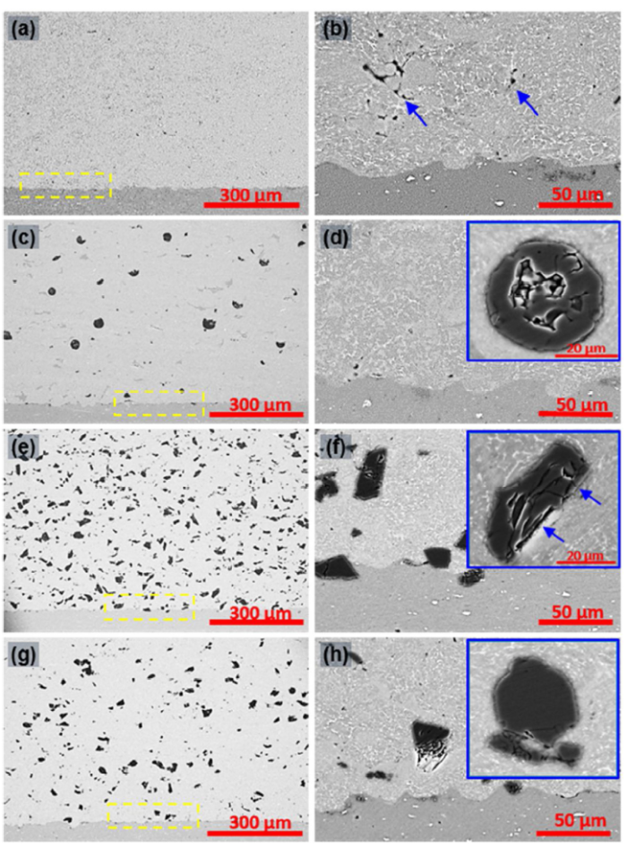
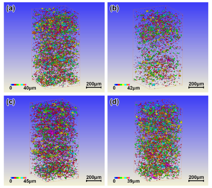
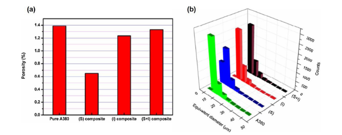
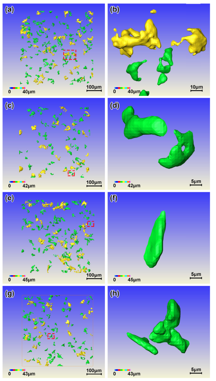
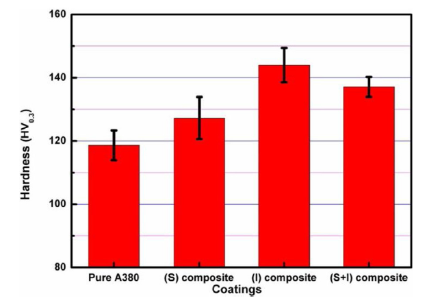
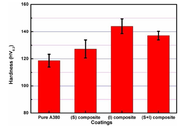
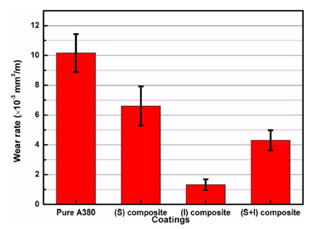
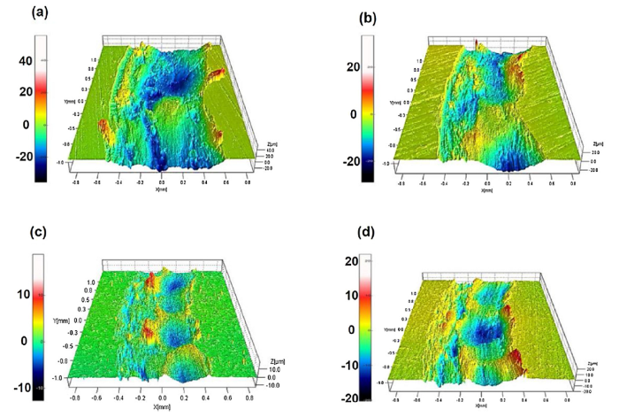
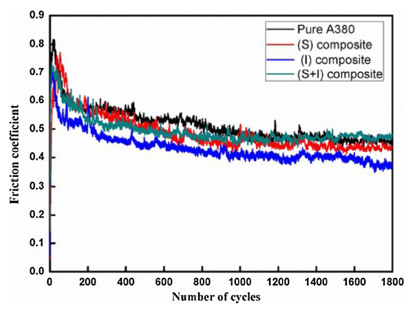