Search for articles:
Qian Yan, Bo Song , Yusheng Shi
Corresponding authors:
Received: 2019-04-28
Revised: 2019-08-4
Accepted: 2019-08-14
Online: 2020-03-15
Copyright: 2020 Editorial board of Journal of Materials Science & Technology Copyright reserved, Editorial board of Journal of Materials Science & Technology
More
Abstract
The influence of the microstructure on mechanical properties of AlSi10Mg fabricated by casting and selective laser melting (SLM) were investigated and contrasted in this work, with an emphasis on understanding the forming mechanism. The microstructure, phase structure and mechanical properties were characterized by scanning electron microscopy/field-emission Transmission Electron Microscopy (SEM/TEM), X-Ray Diffraction (XRD), tensile and fatigue tests. The results indicated that the SLM AlSi10Mg exhibited a supersaturated Si network structure precipitated along α-Al cell. Brittle β-Al5FeSi and π-Al8FeMg3Si6 phases were found in the as-cast and SLM AlSi10Mg respectively due to different thermal histories during processing. The SLM AlSi10Mg showed higher tensile strength but lower elongation than the casting, as the result of grain refinement and tortuous crack path. The fatigue results revealed that unmelted powder, oxide inclusion and pores can considerably degrade the fatigue properties for the SLM AlSi10Mg. The SLM process offered a new method for material processing that would avoid harmful Fe-bearing intermetallic compounds and refine the microstructures for enhancing strength.
Keywords:
Aluminum alloys are prevalent in various manufacturing methods for their attractive properties, such as low density, high specific strength, high thermal and electrical conductivity, excellent oxidation and corrosion resistance [[1], [2], [3]]. Among all the aluminum alloys, the Si-rich Aluminum alloys, mainly AlSi7Mg [4], AlSi10Mg [5,6] and Al-12Si [7,8] with a large volume fraction of Al-Si eutectic, exhibit good flowability and a crack-free tendency during solidification. They are originally developed for casting, and provide a variety application fields in the aerospace and automotive industries. The mechanical properties of Si-rich aluminum alloys are mainly characterized by the morphology of brittle Si particles in eutectic microstructure [9]. Recently, additive manufacturing techniques attract great attention in the aerospace community because they can process metal parts with complex shapes and fine structures, such as thin walled structures and internal cavities, with great freedom of design [[10], [11], [12]]. The high utilization of raw materials and short process cycle extensively can also expand their application [13]. In addition, the strength of the additive manufactured alloys can even be increased by in-situ forming amorphous, nanocrystalline or ultrafine grained structures compared to traditional methods [14]. Selective laser melting (SLM), as a widely used metal additive manufacturing technique, opens new opportunities in the highly customized and high-strength alloys [15].
Specially, the Si-rich aluminum alloys have been widely used in SLM process due to their favorable castability and flowability, satisfactory weldability, reduced shrinkage, and low melt point. In addition to the own characteristic of eutectic aluminum alloy, many researchers have found the SLM process could effectively suppress the continuous growth of the Al grains and form substantially ultrafine-grained particles to improve mechanical properties due to the extremely the high heating and cooling rate reaching 107 K/s during solidification [[16], [17], [18]]. Yu et al. [19] confirmed that using re-melting strategies could improve surface quality and release porosity by allowing pores to escape from the melting pools. Meanwhile, different scanning strategies could change anisotropy of matrix microstructure and inhomogeneity in particle distribution [20]. For example, re-melting could also lead to grain refinement and higher microhardness for SLM AlSi10Mg. Marola et al. [21] have established the correlation between the microstructure, phase constitution and the thermal behavior of AlSi10Mg samples produced by various rapid solidification techniques. The higher is the cooling rate, the broader and lower are the reflections pointing to the increased supersaturation and the reduced crystallite size. Thijs et al. [22] have found the face centered cubic aluminum cells are decorated by a diamond-like silicon phase in the SLM AlSi10Mg, growing towards the center of melt pool. The very fine submicron cells microstructure leads to a higher hardness during SLM process than that during casting. In order to illustrate the underlying reason of unique cellular structure and mechanical properties, Chen et al. [23] have reported the strain-hardening behavior and the strengthening mechanism of SLM AlSi10Mg. A large amount of dislocations could be sustainably produced when dislocation loops repetitively produced in Al crystals around eutectic Si in different cell microstructures, which will simultaneously contribute to a strong strain-hardening effect and high strengths (300 MPa in YS and 455 MPa in UTS).
Al-Si12 is also a typical Si-rich aluminum alloy. Kang et al. [24] have systematically studied the microstructure and strength of in-situ SLM Al-Si12. The distribution and morphology of nano Si particles are significantly influenced by processing parameters, leading to the changes in tensile strength and elongation. However, when increasing the laser power, SLM Al-Si12 possesses larger Si particles as a result of an extended solidification time, showing a poor wear resistance [25]. To improve the properties of Al-Si alloys, Prashanth et al. [26] also used SLM technology to fabricate Al-12Si-TNM composites, and discovered that the composites showed better compressive strengths and wear properties than SLM Al-Si12. Tailoring the precipitation and coalescence of the Si particles can be used to solve the problem of low ductility. Li et al. [27] further revealed that SLM Al-Si12 alloy exhibits significantly better tensile strength and approximately 25% ductility than traditionally prepared parts by changing the solution heat treatment time. In fact, the above-mentioned studies focused on the traditional aluminum alloys designed for casting, which is equilibrium solidification during process. However, SLM process experiences the high heating and cooling rate during solidification, and the melt pool endures continuous thermal cycling and complex physical/chemical reactions [28]. The inhomogeneous heat distribution generally leads to high residual stress levels and a very low ductility for SLM parts [29]. Therefore, it is doubtful whether traditional casting aluminum alloys are suitable for SLM process. Therefore, a comprehensive forming mechanism analysis between the microstructure and mechanical properties of the as-cast and SLM AlSi10Mg is necessary, which can guide the new alloys design for SLM process.
In this work, the casting and SLM process were employed to prepare the AlSi10Mg alloy with significantly different microstructures and properties. The inconsistency of tensile and fatigue behavior between the as-cast and SLM AlSi10Mg has been investigated. Various characterization methods were also performed to explain the effect of two processing methods on performance differences and the forming mechanism.
By the way of vacuum induction atomization, the AlSi10Mg prealloyed powder (FalconTech Co., Ltd., China) used in the SLM process has a nearly spherical morphology, while some small satellite particles were combined with large particles (Fig. 1(a)). Fig. 1(b) shows the size distribution of AlSi10Mg powder used in SLM process, which has an average particle size of 26.9 μm. The AlSi10Mg castings were supplied by Baoji ZhiYi Titanium Manufacturing Co., Ltd., Shanxi, China. The chemical compositions of raw powder and SLM samples were tested by Electron probe micro-analyzer (EPMA-8050 G, SHIMADZU, Japan), and were listed in Table 1.
Fig. 1. SEM morphology (a) and size distribution (b) of AlSi10Mg powder.
Table 1 Chemical composition of raw powder and SLM samples (wt.%).
| Mg | Si | Fe | Ca | Al |
|---|---|---|---|---|
| 0.345 | 9.617 | 0.130 | 0.049 | Balance |
| 0.338 | 9.544 | 0.137 | 0.012 | Balance |
The SLM AlSi10Mg samples were fabricated on EOS M280, which is equipped with a 400 W Yb-fibre laser. After previous process optimization, SLM process was conducted using a laser power of 300 W and a scan speed of 1200 mm/s under the protective atmosphere of Ar. The layer thickness was 30 μm and the hatch spacing was 140 μm. The substrate was pre-heated to 100 °C to reduce internal stress and deformation during rapid cooling process. In order to study the effect of the building direction on the microstructure and tensile property of SLM AlSi10Mg, the cylindrical samples were both fabricated along XY and YZ direction (Fig. 2). The density of SLM AlSi10Mg measured by using the Archimedes method reaches up to 2.64 g/cm3 (2.78 g/cm3 for as-cast AlSi10Mg).
Fig. 2. Schematic representation of building directions of cylindrical SLM AlSi10Mg samples.
The phase composition varied from 20° to 90° of AlSi10Mg samples was conducted using X-Ray Diffraction (XRD-7000S, Shimadzu, Japan) operating with a Cu anticathode (λ = 1.5406 Å) at 35 kV and 40 mA, using a continuous scan mode of 10°/min. After mechanically polished and chemically etched with Keller reagent (1% HF, 2.5% HNO3, 1.5% HCl and 95% H2O) for 10-20 s, the microstructure, tensile and fatigue facture of AlSi10Mg samples were characterized using metallographic microscope (Axiovert 200MAT, Carl Zeiss, Germany) and scanning electron microscopy (SEM, JSM-7600 F, JEOL, Japan), which is also equipped with an energy dispersive spectroscopy (EDS) system for further analyzing element distribution. The further analysis of microstructure was carried out by field-emission transmission Electron Microscopy (FTEM, Tecnai G2 F30, FEI, Holland, 200 kV) using high-resolution transmission electron microscopy (HRTEM) and selected area electron diffraction (SAED) pattern. According to ASTM E8/E8M standard, the tensile behavior was tested at a constant strain rate of 2 mm/min using high-precision electronic universal testing machine (AG-100KN, Shimadzu, Japan) under room temperature (25 °C) and high temperature (230 °C). Fatigue tests (ASTM E466 standard) were performed using the fatigue testing machine (INSTRON 8801, Instron, America) at room temperature with the frequency of 50 Hz and the stress ratio R = 0.1.
Fig. 3 shows the XRD patterns of the as-cast and SLM AlSi10Mg. In Fig. 3(a), typical α-Al phase and eutectic Si were detected in SLM AlSi10 M. It’s concluded that Si is supersaturated and precipitates in Al matrix because of the rapid cooling during SLM process. In addition, the Al (200) peak of SLM AlSi10Mg along the YZ direction (longitudinal section) has stronger intensity than SLM AlSi10Mg along the XY direction (cross section). For cubic AlSi10Mg, the <100> crystal orientation is parallel to the long axis of the columnar grains, and is the preferential crystal growth direction due to its least atomic packing density [7,30]. The different textures of SLM AlSi10Mg along XY and YZ directions indicates that the YZ direction is the primary heat flow direction, and columnar α-Al grains grow along (200) crystal facet, as a result of the preferential solidification along the <100> crystal orientation. For as-cast AlSi10Mg, a few β-Al5FeSi phases are formed (Fig. 3(b)) and the intensity of the Si peaks is rather weak, indicating subtotal Si solved into Al matrix. The harmful Fe-bearing intermetallic compound [31] is prone to generate during equilibrium solidification at lower cooling rates.
Fig. 3. (a) XRD patterns of AlSi10Mg powder, casting and SLM samples; (b) magnified area of AlSi10Mg casting in dotted box in (a).
The metallurgical structure and pore distribution of the SLM AlSi10Mg are shown in Fig. 4. Pores are generally a result of entrapped inactive gas and unfilled gap between stacking layers. The porosities of the SLM samples were calculated using the Image-Pro Plus software to characterize subsurface defects. Compared with the as-cast AlSi10Mg with nearly full densification, there are 0.5% pores with the mean diameter of 3.07 μm in SLM AlSi10Mg along the XY direction (Fig. 4(a)), and 0.8% pores with the mean diameter of 3.15 μm along the YZ direction (Fig. 4(b)).
Fig. 4. Optical micrographs and pore size distribution of SLM AlSi10Mg built along (a) XY and (b) YZ direction.
The surface morphologies of the melt pool along XY and YZ directions are presented in Fig. 5. The XY direction of SLM AlSi10Mg, i.e. cross section, shows interlaced melt pool boundary (Fig. 5(a, b)), while the YZ direction exhibits ordered fish-scale feature towards the building direction (Fig. 5(c, d)). Meanwhile, the overlapping melt pools along XY and YZ directions both consist of three zones: fine grain zone (FGZ) growing towards the center of melt pool, coarse grain zone (CGZ), and heat affected zone (HAZ) at the boundary. Gray network structure with different average size in FGZ and CGZ, and broken particles in HAZ, are caused by different diffusion rates of the precipitated Si element under gradient cooling rates of melt pool. Therefore, the ultrafine Al cells are even coarser near the melt pool boundary (CGZ) than the surface (FGZ) due to the lower cooling rate. Besides, most of Al cells surrounded by Si particles are equiaxed in the SLM AlSi10Mg along the XY direction, while Al cells in the YZ direction are elongated along the building direction. Because of the columnar crystal growing perpendicularly to the direction of powder deposition, the Al cells use dendrites in FGZ as a substrate to grow epitaxially into CGZ. Therefore, the FGZ in the overlapped the molten pool disappears in the SLM AlSi10Mg along the YZ direction.
Fig. 5. SEM images showing melt pool morphologies of SLM AlSi10Mg built along (a, b) XY and (c, d) YZ direction.
EDX analysis was also conducted to characterize the distribution of Al, Si and Mg elements in the as-cast and SLM AlSi10Mg (Fig. 6). Granular precipitated phases existed in the as-cast AlSi10Mg, while only melt pool could be observed in the SLM AlSi10Mg at a lower magnification. Combined with XRD results of the as-cast AlSi10Mg, Si and Mg elements are solved and evenly distributed in Al matrix, which verifies no serious Si precipitation phase in the as-cast AlSi10Mg (Fig. 6(a-c)). Plenty of precipitated Si network structure in the SLM AlSi10Mg indicates that the liquid of approximately eutectic composition solidifies to form eutectic Si along Al cell boundaries, typically on the scale of about 500-1500 nm (Fig. 6(d-f)).
Fig. 6. EDS analysis on microstructure of (a-c) the as-cast and (d-f) SLM AlSi10Mg.
Detailed microstructure and precipitated phases of the as-cast and SLM AlSi10Mg are further observed via TEM as shown in Fig. 7, Fig. 8. The TEM micrograph in Fig. 7(a) and (d) exhibits that lamellar precipitated phase on scale of about 100 nm is evenly distributed across all Al matrix. Quantitative EDS analysis of the precipitated phase shows that the composition of the as-cast AlSi10Mg is approximately 73.86 at.% Al, 14.66 at.% Si, 1.09 at.% Mg, and 10.39 at.% Fe, which is similar to that of β-Al5FeSi phase [32]. A representative HRTEM micrograph with the corresponding fast-Fourier transformation for the Fe-bearing precipitate is presented in Fig. 7(e), indicating that the [1 $\bar{1}$ 0] crystal orientation of the lamellar precipitate matches the monoclinic crystal structure of β-Al5SiFe phase. Fig. 8(a) presents TEM micrograph of the SLM AlSi10Mg, clearly demonstrating the enrichment of eutectic Si along the α-Al cell boundaries. According to EDS mapping in Fig. 8(b) and (c), in addition to Si network structure, Fe and Mg were only segregated along the interlaced edge of cell boundaries. The chemical composition of the Fe-bearing precipitate in the SLM AlSi10Mg was approximately Al59.40Si23.46Mg12.00Fe5.14, similar to that of π-Al8Si6Mg3Fe phase. HAADF micrograph in Fig. 8(d) shows that the cell boundary is composed of overlapped nanometer-sized particles. A SADP pattern from the cell boundary is presented in Fig. 8(e), which corresponds to a Si ring pattern and several discrete Al diffraction spots along the [200] crystal orientation. HRTEM micrograph and the corresponding FFT in Fig. 8(f) further confirms that, besides tiny Si particles, a few hexagonal π-Al8FeMg3Si6 precipitate phases are aligned along the [0 1 $\bar{1}$ 1] crystal orientation in Al matrix.
Fig. 7. TEM observations of as-cast AlSi10Mg: (a, d) TEM micrograph of precipitated phase; (b) EDS elemental mapping and (c) elemental distribution of Al, Si, Mg and Fe within the square marked in (a); (e) HRTEM micrograph and the corresponding FFT of lamellar precipitated phase.
Fig. 8. TEM observations of SLM AlSi10Mg: (a) HAADF TEM micrograph of network structure; (b) EDS elemental mapping and (c) elemental distribution of Al, Si, Mg and Fe within the square marked in (a); (d) HAADF TEM micrograph of and (e) the corresponding SAED pattern of Al cell boundary; (f) HRTEM micrograph and the corresponding FFT of overlapped boundary.
The different microstructures and distribution of participations in the as-cast and SLM AlSi10Mg are caused by two thermal histories of metal liquid solidification. For Si-rich Al alloys, the solubility of Si is affected by melt temperature, and it significantly reduces with the increasing temperature. Therefore, partial Si element solved into Al matrix for as-cast AlSi10Mg, while most Si existed as the precipitated network structure round ultrafine Al cells in SLM AlSi10Mg due to instantaneous ultra-temperature. Different Fe-bearing precipitates are formed in the as-cast and SLM AlSi10Mg due to diverse cooling rates during process [33]. In addition, intricate Fe-bearing intermetallic compounds with low solubility tends to form with other elements in aluminum alloy, which will undergo isomeric transformation of α-β-γ under different solidification temperatures [34,35]. For the as-cast AlSi10Mg, lamellar β-Al5SiFe phase is prone to nucleate in γ-Al matrix as a result of equilibrium solidification at lower cooling rates during casting process. Because of the rapid cooling rates during SLM process, γ-Al phase will transform into the α-Al phase, which can effectively reduce the nucleation sites of Fe-bearing phases [31]. On the other hand, abundant eutectic Si participates decrease the formation of other Si-bearing phases. Therefore, π-Al8Si6Mg3Fe phase rarely exists on the edge of interlaced network structure in SLM AlSi10Mg (Fig. 9).
Fig. 9. Mechanical properties of common Al-Si alloys prepared by SLM or casting. And our results compared with them [7,23,[
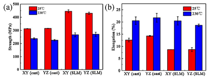
The aircraft is developing promptly in the direction of high-speed and high-pressure. When the speed of aircraft reaches 2.7 times more than that of sound, the surface temperature of aircraft reaches 230 °C. Therefore, it is necessary to study the high temperature tensile properties of AlSi10Mg alloy used in the aerospace industry. Compared to other research about AlSi10Mg, the as-cast and SLM AlSi10Mg in this experiment show a slightly lower strength but a higher elongation. Fig. 10 and Table 2 show the tensile results for the as-cast and SLM AlSi10Mg testing at 25 °C and 230 °C. Apparently, the strength and elongation of the as-cast and SLM AlSi10Mg built along different directions are not identical. The SLM AlSi10Mg possesses a higher tensile strength than the castings at 25 °C and 230 °C, even obtains a similar elongation to the castings at 230 °C. At 25 °C, the SLM AlSi10Mg without apparent yield stage has a relatively higher tensile strength (445 ± 11 MPa along the XY direction and 430 ± 9 MPa along the YZ direction) compared to the as-cast AlSi10Mg (313 ± 1 MPa along the XY direction and 315 ± 1 MPa along the YZ direction) at the expense of elongation. Among the four types of AlSi10Mg, the SLM AlSi10Mg along the XY direction exhibits the highest strength, even have a slightly higher elongation than that along the YZ direction. When testing at 230 °C, the plasticity of the as-cast and SLM AlSi10Mg both improves greatly, due to the elevated atomic activity and reduced internal defects at high temperature. Meanwhile, the gap of the tensile strength and elongation between the as-cast and SLM AlSi10Mg has narrowed. The tensile strength of the SLM AlSi10Mg (267 ± 15 MPa along the XY direction and 270 ± 17 MPa along the YZ direction) is ∼30 MPa higher than that of the as-cast AlSi10Mg, while the elongation of the SLM AlSi10Mg dramatically increases from 8% to 20%.
Fig. 10. Tensile strength (a) and elongation (b) of as-cast and SLM AlSi10Mg.
Table 2 Tensile results of as-cast and SLM AlSi10Mg.
| Processing methods | Direction | Temperature | Tensile strength (MPa) | Elongation (%) |
|---|---|---|---|---|
| Casting | XY | 25 °C | 312.65 ± 1.34 | 12.60 ± 0.77 |
| YZ | 315.13 ± 1.33 | 14.29 ± 0.19 | ||
| SLM | XY | 445.34 ± 11.36 | 8.68 ± 0.02 | |
| YZ | 430.04 ± 8.88 | 8.70 ± 0.82 | ||
| Casting | XY | 230 °C | 237.16 ± 6.13 | 20.47 ± 1.70 |
| YZ | 225.31 ± 5.46 | 18.67 ± 0.49 | ||
| SLM | XY | 266.59 ± 15.25 | 20.53 ± 1.55 | |
| YZ | 270.19 ± 15.86 | 21.73 ± 1.80 |
Considering anisotropy in tensile properties due to different types of processing methods, fracture analysis is necessary for understanding the tensile properties of the as-cast and SLM AlSi10Mg. Fig. 11 displays the fracture surface images of the as-cast and SLM AlSi10Mg built along different directions. Dimples accumulation exists in the micro-fracture surface of the as-cast AlSi10Mg built along the XY direction, while obvious necking phenomenon (Fig. 11(c)) and abundant dimples (Fig. 11(d)) of the as-cast AlSi10Mg built along the YZ direction also confirm ductile fracture, leading to the largest deformation and elongation among four types of AlSi10Mg. The brittle fracture of the SLM AlSi10Mg propagates through Si network structure, leaving abundant cavities because of Si particles escaping from Al matrix. Furthermore, larger holes in the fracture surface result from unmelted powders, oxide inclusions or internal pores. Considering the overlapped laser tracks, the fracture of the SLM AlSi10Mg along the XY direction (Fig. 11(e)) shows a disorder propagation path, while the crack path along the YZ direction (Fig. 11(g)) is more regular and flatter, corresponding to the shape of laser tracks. The more torturous crack propagation mode of the SLM AlSi10Mg built along the XY direction leads to the improved strength and elongation than along the YZ direction, which is in line with tensile results.
Fig. 11. SEM images of fracture surface images for (a, b, c, d) the as-cast and (e, f, g, h) SLM AlSi10Mg built along (a, b, e, f) XY and (c, d, g, h) YZ direction.
Since the morphology of brittle Si particles greatly affects the mechanical properties of AlSi10Mg. The as-cast AlSi10Mg shows improved elongation for the mostly solved Si element and nanometer-sized Fe-Si precipitates, while the Si element exists as coarser interconnected particles in the SLM AlSi10Mg. Meanwhile, network structure in the SLM AlSi10Mg also prevents the plastic deformation of Al matrix when stretching, and the SLM AlSi10Mg possesses ultrafine Al cells, leading to higher tensile strength than the castings. However, tensile force parallel to the building direction is prone to cause brittle fracture due to the defects of overlapped and not tightly connected laser tracks during SLM process. There are both Fe-bearing intermetallic compounds poorly soluble in Al matrix of the as-cast and SLM AlSi10Mg. Stress concentration will form around the brittle phases to generate microcracks preferentially in plastic deformation [[42], [43], [44]]. Therefore, the evenly dispersed β-Al5SiFe phase in the as-cast AlSi10Mg severely separates the Al matrix, resulting in more crack sources than SLM AlSi10Mg and the reduced tensile strength. However, the brittle β-Al5SiFe and Al8Si6Mg3Fe phases with high melting points and hardness are able to strengthen the Al matrix and resist deformation at high temperature [[31], [32], [33]]. The uniformly distributed β-Al5SiFe phase improved tensile performance of the as-cast AlSi10Mg under high temperature. Consequently, the as-cast and SLM AlSi10Mg possess closer tensile properties when testing at 230 °C.
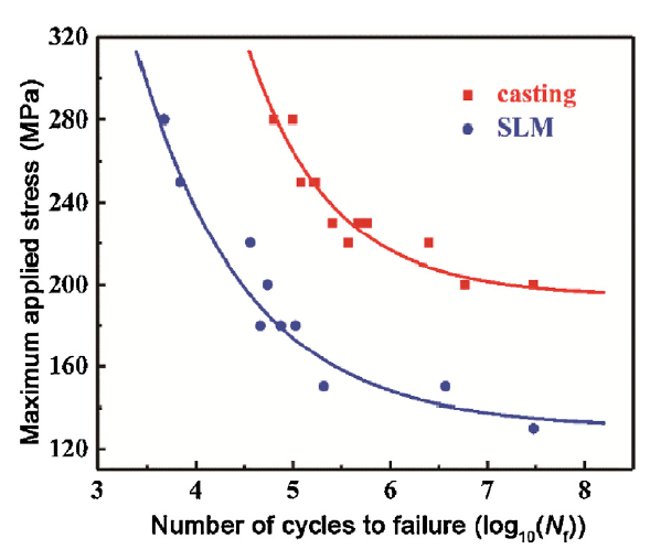
Considering the worse tensile properties, the fatigue limits of the as-cast and SLM AlSi10Mg built along the YZ direction were only discussed instead of AlSi10Mg built along the XY direction. The S-N curves of the as-cast and SLM AlSi10Mg built along the YZ direction are shown in Fig. 12. The fatigue limit of the SLM AlSi10Mg (Sf = 130 MPa, Nf=107 cycles) is lower than that of castings (Sf = 200 MPa, Nf=107 cycles). The locations with stress concentration of the mechanically polished as-cast and SLM AlSi10Mg lead to the decrease of fatigue resistance.
Fig. 12. S-N curves of the as-cast and SLM AlSi10Mg built along YZ direction.
Fracture morphology of the as-cast and SLM AlSi10Mg was then characterized to find the crack origin and propagation modes. Under tension-compression cyclic loading, the dislocation density raises with the increase of cycle times, and the aggregation of dislocation leads to microcracks at internal defects, such as pores and solidification defects. Once bearing tensile stress, new surface forms when plastic deformation occurs at the microcrack tips, then the new surface is closed to further form a new microcrack when bearing compression stress. Consequently, microcracks extend to the entire surface of fatigue samples, generating final fracture [[45], [46], [47]]. SEM images in Fig. 13, are composed of fatigue source, fatigue crack propagation and final fracture, exhibiting typical fatigue fracture. For fatigue samples breaking under approximate fatigue limit, a single fatigue crack started on the periphery of samples, at locations with stress concentration, such as solidification defects for the as-cast AlSi10Mg under 200 MPa (Fig. 13(a)), and unmelted powder or oxide inclusion for the SLM AlSi10Mg under 150 MPa (Fig. 13(b)). Except the oxidized vapor or spatter, oxide inclusion is also associated with the native oxide film of the powder particles during SLM process [39]. More internal defects are inclined to form in the SLM parts than in the castings.
Fig. 13. SEM images of fatigue fracture surfaces for (a) the as-cast and (b) SLM AlSi10Mg under approximate fatigue limit.
Fig. 14 presents the effect of fatigue stress on fatigue crack propagation of the as-cast and SLM AlSi10Mg. All the fatigue sources are located in the periphery of samples bearing different stresses. Compared with the as-cast AlSi10Mg with a single fatigue source, the SLM AlSi10Mg generates multiple fatigue sources under high stresses. Furthermore, the fatigue crack propagation zone expands as the fatigue stress increases both for the as-cast and SLM AlSi10Mg. When bearing higher stress, the fatigue source is easier to generate with less microcrack opening-closing process, resulting in rougher fracture surface. On the contrary, the crack of SLM AlSi10Mg rapidly propagates, resulting in more flat fracture surface with lower cycle times.
Fig. 14. Development of fatigue fracture surface at different stress levels for (a, b, c) the as-cast and (d, e, f) SLM AlSi10Mg.
Typical regions of the end of fatigue crack propagation zones, and final facture zones of the as-cast and SLM AlSi10Mg are displayed in Fig. 15. Significant differences are observed when testing at 250 MPa. For the as-cast AlSi10Mg with rougher surface, flat face consists of multiple wavy regions as a result of microcrack opening-closing process. Parallel fine striations in the crack paths of crack propagation zone (Fig. 15(a)) indicate good plasticity. Ductile fracture surface with large dimples on the scale of about of 5 μm and some secondary particles are also observed in final facture zone. As for the SLM AlSi10Mg, cavities caused by inclusions and pores distribute in the whole fracture. River pattern appears in fatigue propagation zone, and propagation direction is identified as black arrow. In addition, the final fracture morphology (Fig. 15(d)) is similar to tensile fracture, showing tearing microcracks and shallow dimples caused by the eutectic Si particles. Therefore, the SLM AlSi10Mg is relatively one type of brittle materials than the as-cast AlSi10Mg.
Fig. 15. SEM images of fracture surface for (a, b) the as-cast and (c, d) SLM AlSi10Mg in (a, c) crack propagation and (b, d) final fracture condition under 250 MPa.
There are more internal defects such as abundant cavities, pores, unmelted powders and oxide inclusions, and heterogeneous structure formed in SLM process, causing more microcracks and worse fatigue resistance than the castings. Besides, typical fracture morphologies of the crack propagation zone and final fracture zone correspond to the microstructure of AlSi10Mg. Intergranular failure of the as-cast AlSi10Mg generates along Al grain boundaries, leading to coarse dimples in the final fracture zone. For SLM AlSi10Mg with smaller dimples, the microcracks propagate along the boundary of ultrafine Al cells, which are surrounded by eutectic Si particles.
This study systematically investigated the microstructure, mechanical performance and the corresponding forming mechanism of the as-cast and SLM AlSi10Mg, including the phase, internal defect, surface morphology, anisotropy of tensile performance, and fatigue life. The main conclusions drawn from this work are as follows:
(1) The microstructure of the SLM AlSi10Mg is distinct from the casting. Lamellar β-Al5SiFe was uniformly distributed in casting, while π-Al8Si6Mg3Fe existed in the overlapped edge of Si network structure for the SLM AlSi10Mg.
(2) The SLM AlSi10Mg showed anisotropy. Preferential solidification of Al grains along <100> led to stronger intensity (200) of the YZ direction. The disorder propagation path perpendicular to the overlapped laser tracks improved tensile strength in the XY direction.
(3) Great performance differences appeared between the as-cast and SLM AlSi10Mg. The SLM AlSi10Mg possessed higher tensile strength due to grain refinement and different precipitated phases. More serious internal defects and coarser precipitates decreased fatigue limit of the brittle SLM AlSi10Mg.
(4) The thermal behavior had much influence on the grain size, solid solubility and Fe-bearing phases during casting or SLM process. Ultrafine Al cells and diverse precipitates changed the type of crack initiation and propagation, and the interaction between powder and laser caused more internal defects for the SLM AlSi10Mg.
This work was financially supported by the Boeing Company/HuaZhong University of Science and Technology Project “Compressor wheel production by laser additive manufacturing using Ti and Al alloy powders” (No. 2016-495), the Hubei Science Fund for Distinguished Young Scholars (No. 0216110085), the Wuhan Morning Light Plan of Youth Science and Technology (No. 0216110066), the Academic Frontier Youth Team (Nos. 2017QYTD06 and 2018QYTD04) at Huazhong University of Science and Technology (HUST). The authors thank the Analytical and Testing Center of HUST for SEM examination and the State Key Laboratory of Materials Processing and Die & Mould Technology for tensile tests.

 WeChat
/
| 〈 |
|
〉 |


