Search for articles:
S.J. Tsianikas , Y. Chen, Z. Xie
Corresponding authors:
Received: 2019-05-9
Revised: 2019-06-26
Accepted: 2019-07-27
Online: 2020-02-15
Copyright: 2020 Editorial board of Journal of Materials Science & Technology Copyright reserved, Editorial board of Journal of Materials Science & Technology
More
Abstract
Hierarchical CrCoNi medium entropy alloy (MEA) thin films with a duaerarchical CrCoNi medium entropy alloy (MEA) thin films with a dual-phase face-centred cubic (FCC) and hexagonal closed-packed (HCP) nanostructure were prepared on M2 steel substrates by closed field unbalanced magnetron sputtering. Nanoindentation tests show an ultra-high hardness of 9.5 GPa, attributable to large amounts of innate planar defects (i.e., growth twins and stacking faults) impeding dislocation motion in the coatings. A deep analysis of undeformed and post-mortem samples reveals grain refinement as the dominant deformation mechanism in FCC dominated regions, while phase transformation and shear banding played major roles in regions occupied by HCP phase. The grain refinement was facilitated by twin/matrix lamellae, with dislocations piling up and arranging into interconnecting grain boundaries. The shear banding was accelerated by innate planar defects in the HCP phase due to a lack of slip systems. Of particular interest is the observation of HCP → FCC phase transformation, which was catalysed by deformation-induced grain reorientation with innate stacking faults acting as embryos to grow the FCC phase. The results of this work suggest that multiple deformation pathways could be activated in CrCoNi coatings with assistance of growth defects, thereby imparting these technically important coatings appreciable ductility.
Keywords:
Following the discovery of high entropy alloys (HEAs), ternary alloy systems termed medium entropy alloys (MEAs) have emerged and are promising for more impact. This stems from the work of Gali and George [1], who demonstrated that increasing the number of alloying elements from four to five does not always improve the degree of solid solution strengthening. In addition, Wu et al. [2] reported no correlation between mechanical properties and number of principal elements, and, provided examples of alloys with the same configurational entropy but different strengths. The results of these studies and others prove that the nature of elements used is the crucial factor in the creation and development of high-performing alloys, rather than simply the number of principal elements used [3]. A prominent MEA that has been investigated in recent years is the ternary alloy CrCoNi [[3], [4], [5], [6], [7]]. Fabricated in a bulk form, its mechanical properties are superior to that of widely reported quinary alloy CrMnFeCoNi despite having lower configurational entropy [4]. Specifically, its reported tensile strength and ductility are ~1 GPa and ~70%, respectively [3], attributable to interactions between dislocations and 3D twin architectures [7]. More recently, a high hardness (~10 GPa) has been reported in sputter-deposited CrCoNi coatings [8], supposedly attributed to its unique microstructural features including twin boundaries [9], stacking faults, a dual-phase structure, and textured columnar grains [8].
Most HEAs and MEAs are prepared in a bulk form through arc melting and casting, which incurs very high material and energy costs and, therefore, research into HEA and MEA thin-film and coating deposition onto low-cost metal substrates is receiving increased attention [10]. Aside from lowering the costs to a great extent, these films and coatings also exhibit excellent mechanical properties [8,[10], [11], [12], [13], [14], [15]], when compared to their bulk counterparts [8,15].
The efficacy of CrCoNi as a protective coating has been examined by Cao et al. [16,17] and Chen et al. [8]. The incorporation of the Ti wetting layer increases coating adhesion [18] and, more importantly, can cause the grains to change from an elongated shape to much finer equiaxed morphology; induced grain refinement can change from 50 nm to 20 nm [16]. The work of Cao et al. [16,17] looked into the differences between coatings with and without interlayers and rationalised mechanical properties by evaluating the phase composition, grain diameter and defects (innate & post-mortem). Chen et al. [8] examined a monolithic CrCoNi coating via high angle annular dark field (HAADF) scanning transmission electron microscopy (STEM), and shed light on its exceptional mechanical properties by unpacking the hierarchical nanostructure of the as-deposited coating. However, their work and analysis is limited to microstructural characterization, and consequently, the deformation mechanisms of the CrCoNi alloy coating remain unexplored.
In this study, we employed nanoindentation and HAADF STEM techniques to investigate the deformation mechanisms of the CrCoNi coatings with particular focus on structural characterization of both undeformed and post-mortem thin film samples. The CrCoNi coatings synthesised via magnetron sputtering demonstrate an ultra-high hardness, and possess a high density of planar defects, a mixture of FCC & HCP phases, and textured columnar nanograins. This study adds critical insights to previous studies of CrCoNi coating by revealing its deformation mechanisms, featuring (1) HCP → FCC phase transformation, (2) grain refinement and (3) shear banding.
The CrCoNi/Ti coatings were deposited at a rate of ~72 nm/min by closed field unbalanced magnetron sputtering ion plating (CFUMSIP) onto AISI M2 high speed steel substrates, using a UDP650 magnetron sputtering system (Teer Coatings Ltd, UK). The steel substrates were hardened to HRC 60, finely polished to Ra ~0.03 μm, degreased, ultrasonically cleaned, and subsequently blown dry in flowing nitrogen gas. One CrCoNi alloy target (China Material Technology Co. Ltd) with composition of 1:1:1 at%, purity of 99.5% and dimensions of 345 mm × 145 mm × 5 mm was used for the deposition. The substrates were stationary during deposition, and the target-to-substrate distance was fixed at 170 mm. The substrate holder was biased with pulsed DC at a frequency of 250 kHz. The vacuum chamber was pumped down to a background pressure of < 2 × 10⁻⁶ Torr by controlling the flow rate of Ar (50 sccm). The DC current applied to the CrCoNi target was fixed at 4.0 A (sputtering power 1.5 kW). The deposition process of the coatings comprises three major steps: plasma ion cleaning (-450 V bias, 30 min), Ti interlayer deposition (-60 V bias, 200 nm thickness), and CrCoNi deposition (-60 V bias, 14 min). Ion etching of the steel substrates at the first stage was used to remove the oxide layer and contaminants on the substrate surface. The CrCoNi target current (DC) was maintained at 4.0 A (sputtering power ~1.5 kW), corresponding to a nominal deposition rate of ~72 nm/min. The titanium target current (DC) was set at 4.0 A (sputtering power ~ 1 kW), corresponding a nominal deposition rate of 10 nm/min. No external heating was used during coating deposition.
Focussed ion beam milling (FIB) (FEI Helios Nanolab 600, The Netherlands) was used to prepare and extract thin sections to a thickness of ~50 nm for analysis via scanning transmission electron microscopy (STEM) and energy dispersive X-ray spectroscopy (EDX) (Titan Themis 80-200, The Netherlands). The microstructure was studied with a field emission transmission electron microscope (TEM) (Phillips CM200, Netherlands).
A nanoindentation system (Fischer-Cripps Laboratories IBIS Nanoindenter, Australia) equipped with a Berkovich indenter was used to measure mechanical properties, viz. hardness (H) and modulus of elasticity (E). Calibration of this instrument was routinely performed with a standard fused quartz specimen (Er ~ 69 GPa). The load function consisted of a loading up to 50 mN, and then an unloading. The penetration depth corresponded to about 10% of the total film thickness to minimise the effect of the substrates, and the hardness and modulus were calculated using the Oliver-Pharr method [19]. The values reported are an average of fifteen indentations, and the standard deviation was also calculated and provided. In order to prepare deformed samples for TEM analysis, a spherical indenter (radius = 5 μm) was used at loads of 200 mN and 400 mN.
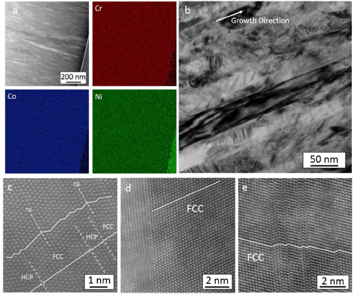
Fig. 1(a) shows EDX mapping for the undeformed sample, revealing a homogenous distribution of Co, Cr and Ni atoms (and therefore no locally enriched regions). The microstructure obtained via TEM (Fig. 1(b)) shows a columnar grain structure, with grain widths of approximately 20-30 nm. It consists distinctive regions of; perfect FCC, FCC with stacking faults, FCC with twinning, and alternating FCC & HCP phases within a single column (Fig. 1(c-e), respectively). Extensive STEM investigations reveal that these unique regions are randomly distributed within each columnar grain. A close examination indicates that regions of mixed FCC and HCP are predominantly FCC, with the HCP volume fraction varying between 25% and 40%. The volume fraction of HCP was calculated by dividing the thickness of HCP lamellae by the total thickness (i.e. HCP + FCC) examined in five columnar grains observed in STEM images, and was found to be larger close to the substrate and smaller near the surface.
Fig. 1. As-deposited CrCoNi sample; (a) EDX mapping of a selected region of the sample shown in the top-left pane. A small segment of platinum is included in the bottom-right for reference, (b) nanocolumnar structure, (c) alternating HCP and FCC phases, with twinning present, (d) perfect FCC crystal and grain boundary, and (e) FCC region with stacking faults.
The results of the nanoindentation testing are shown in Table 1. The wear parameters H/E and H3/H2 values are also tabulated, which represent the material’s elastic strain to failure, and resistance to plastic deformation, respectively [20]. The values of hardness (H) and modulus of elasticity (E) measured are similar to those obtained by Cao et al. [16,17] and Chen et al. [8]. Compared to other HEAs, the CrCoNi samples have a relatively high hardness and wear parameters. Its values are near those of AlCoCrCuFeNi, which represents the highest values ever reported.
Table 1 Nanoindentation Values obtained from this project, and values obtained from literature, with H/E and H3/E2 values.
| Sample | Hardness (GPa) | Young’s Modulus (GPa) | Wear Parameter H/E | H3/E2 |
|---|---|---|---|---|
| CrCoNi/Ti (Present Study) | 9.5 ± 0.1 | 238 ± 4 | 0.0399 | 0.0151 |
| CrCoNi (1 μm and 3 μm) [16] | ~10 | ~250 | 0.0400 | 0.016 |
| CrCoNi/Ti (1 μm and 3 μm) [16] | ~9.2 | ~230 | 0.0400 | 0.014 |
| CrCoNi/Ti (multilayered) [17] | 7.6 ± 0.43 | 233 ± 13 | 0.033 | 0.0081 |
| CrCoNi [8] | 10 | 267 | 0.0375 | 0.014 |
| Co19Cr19.2Fe 19.2Ni 19.1Cu23.5 [38] | 3.72 | 188.5 | 0.0197 | 0.0014 |
| Co13Cr12.2Fe12.4Ni13.2Cu17.7Al31.5 [38] | 2.62 | 174.3 | 0.0150 | 0.00059 |
| Al0.3CoCrFeNi [39] | 3.33 | 216 | 0.0154 | 0.00079 |
| AlCoCrFeNi [39] | 10.1 | 251 | 0.0402 | 0.016 |
| AlCoCrCuFeNi [40] | 8.13 | 172 | 0.0473 | 0.018 |
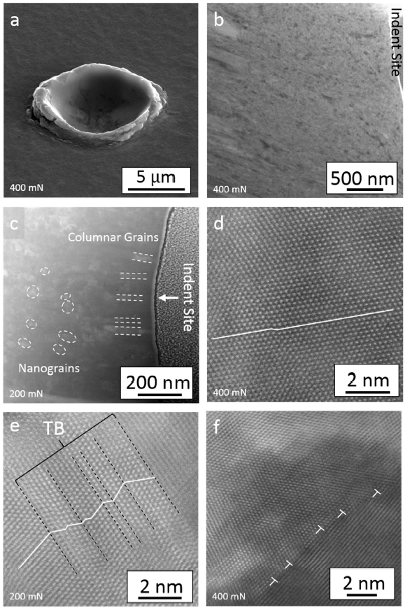
The STEM images of the TEM sample deformed under a load of 400 mN reveal that there are no cracks in the coating, nor can any delamination between coating and substrate be observed. This is an extraordinary response for such an ultra-hard coating, suggesting a possibility to overcome the long-standing hardness-toughness trade-off [7]. There is a pile-up of material at the edge of the indent (Fig. 2(a)), manifesting a metal-like ductile behaviour. Post-mortem TEM shows a high extent of grain refinement under the indent site (Fig. 2(b and c)); grain diameters range between 10 nm and 60 nm, with some columnar grains remaining intact at the indent site at 200 mN (Fig. 2(c)). The microstructure when subject to a load of 200 mN (Fig. 2(e)) consists of twinned FCC region and some stacking faults, whereas at 400 mN (Fig. 2(d)), this twinning is not present, and the number of stacking faults has decreased. The absence of HCP in the nanograins indicates that HCP → FCC phase transformation has most likely occurred. The dislocations at one of the grain boundaries are annotated in Fig. 2(f). Under a load of 200 mN, the columnar grains above the grain refinement region exhibit an FCC structure at the surface, and further down grain refinement precursors are visible, in addition to a structure rich in defects.
Fig. 2. Samples after deformation; (a) indent site showing pile-up; (b and c) microstructures after deformation of 400 mN (b) and 200 mN (c); (d & e) STEM image of nanograins obtained ~1 μm below the sample surface showing an equiaxed grain for 400 mN (d) and twin/matrix lamellae for 200 mN (e), and; (f) dislocations (marked by white ⊥ symbols) at the grain boundary of a nanograin.
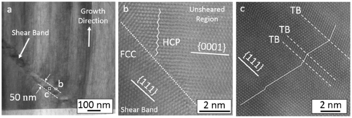
At a load of 400 mN, a shear band is visible near the bottom of the coating towards the Ti wetting layer (Fig. 3(a)); the sharp edges distinguish it from the surrounding intact columnar grains, with a thickness of approximately 50 nm. The shear band is not observed at a load of 200 mN. On close examination of the newly formed nanograins and shear band regions, the phases are entirely FCC (Fig. 3(b and c)), whereas the adjacent un-sheared region (Fig. 3(b)) has an HCP crystal structure, indicating that HCP → FCC phase transformation has taken place within the shear band. In addition, the crystal structure within the shear band has a different orientation to the original structure, suggesting that crystallographic rotation has occurred.
Fig. 3. (a) Shear band region, visible by its very distinguishable edges. STEM images (b) depict the edge of the shear band region and (c) reveal the structure inside the shear band as FCC, with twin/matrix lamellae.
The adhesion of the coatings is not consistent with results reported by Cao et al. [16], who asserted that thicker coatings would experience accumulated stress at the coating/substrate interface during deformation, causing adhesion failure. The non-delamination is further corroborated by observations from the TEM samples which were subject to out-of-plane bending during ion milling; damage would have been evident at the interface if delamination did occur.
In bulk samples prepared via high temperature processes such as casting, the FCC phase is typically formed as it is more thermodynamically favoured than HCP at high temperatures [3,4,7,21]. Upon cooling, the FCC to HCP phase transformation is kinetically hindered due to a high energy barrier between FCC and HCP phase despite HCP having a lower Gibbs free energy at room temperature [8]. The HCP phase is observed in magnetron sputtered coatings [8,16] because it is a low temperature process, allowing for the formation of HCP phase. In addition, it has been suggested that innate planar defects could facilitate a phase transformation from FCC to HCP, via the formation of stacking faults on every second {111} plane [8]. Meanwhile, the variation in relative fraction of HCP from the substrate to the surface can be explained by the temperature gradient which results during deposition. Cao et al. [16] confirmed the presence of both FCC and HCP phases in the CoCrNi coatings with XRD data, however they asserted that the HCP phases are cobalt-only. While STEM images do confirm the presence of HCP and FCC phases, EDX mapping (Fig. 1(b)) indicates all three elements Cr, Co and Ni are homogenously distributed. Given that Cr, Co, and Ni all have similar atomic radii of 0.125 nm (to three significant figures [22]), and the fact that atomic spacings are used to index peaks, it is likely that a peak indexed as cobalt-only in fact has all three elements present.
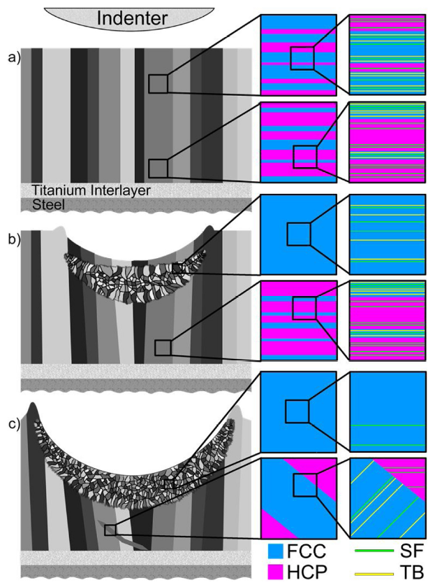
As mentioned in Section 3.3, STEM images of the as-deposited samples possess regions of predominantly FCC single crystal and HCP/FCC lamellae, with multiple stacking faults and twinning (Fig. 4(a)) considered as growth planar defects of a sputtered film [23]. The high hardness of CrCoNi (~9.5 GPa) is attributable to the presence of these planar defects, dual-phase FCC/HCP regions, and nanocolumnar grain boundaries, all of which are known to serve as barriers to dislocation motion [24] thereby bringing about strengthening effects [25]. In addition, HCP has less slip systems present than FCC, therefore its incorporation in the coatings also leads to a higher hardness [8]. The combination of these distinctive structural elements results in a much higher hardness than that obtained for the purely FCC CrCoNi bulk sample [21].
Fig. 4. Generalised deformation mechanism of the CrCoNi coating: (a) pristine columnar structure, HCP/FCC regions and presence of stacking faults and twin boundaries; (b) partial deformation caused by 200 mN showing grain refinement onset beneath the indent site with phase transformation and elimination of some planar defects in nanograins, and; (c) heavy deformation induced by 400 mN, showing further elimination of planar defects in nanograins, and shear band formation.
Prior to the work of Tao et al. [26], it was understood that strain-induced grain refinement occurs solely via dislocation activity. Since the grain refinement mechanism is sensitive to crystal structure (FCC preferred) and the deformation conditions, the plastic deformation of FCC structured materials under certain conditions could lead to multiple deformation twinning and the formation of twin/matrix lamellae [27]. Upon further straining, twin/matrix lamellae are refined into equiaxed nanosized grains with dislocations accumulated into interconnecting bands, which eventually form grain boundaries [27]. Thus, the innate twin/matrix lamellae (Fig. 1(c)) in the as-deposited coatings with FCC as dominant phase provide a conducive environment for grain refinement to take place under applied stress. In addition to the elimination of twin boundaries via grain refinement, nanograins in the heavily deformed sample have a much lower concentration of twin boundaries (Fig. 4(c)). Therefore, detwinning within the FCC phase is another deformation mechanism present in this sample, likely achieved via glide of twin dislocations [28]. As the grains become further refined, detwinning occurs more readily than twinning, eventually leading to the annihilation of twins [29]. Lastly, the preservation of columnar nanograins under a load of 200 mN (Fig. 4(b)) might be due to the fact that the initial structure is nanofibre-like making it very strong, and is therefore prone to buckling when the indentation load was applied [30]. The crystal structure within these columns (described in Section 3.3) also changed under the compressive stress, producing perfect FCC crystal via HCP → FCC phase transformation (discussed below). Upon increased loading, this buckling zone expanded to meet the sample surface, which is why these columnar grains are no longer present at a force of 400 mN.
The extent of phase transformation in the shear band, observable only at a load of 400 mN, is evident, wherein the crystal structure comprises exclusively FCC phase (Fig. 3(b)). Shear band formation requires obstacles to dislocation motion [31], which would preferentially form in HCP phase rather than FCC (as there are less slip systems in HCP structure) and also have a tendency to form in materials with a highly twinned structure [32]. In the present study, the grain refinement is dominant during the early stages of deformation, since the deformed region is primarily composed of FCC phase. Only when subjected to a heavy load (400 mN), HCP phase dominated regions (still well-preserved and rich in planar defects) near the substrate (Fig. 3(b)) experienced deformation, leading to shear band formation under high strain localisation (Fig. 4(c)).
Phase transformation is another deformation mechanism evident in the sample, a mechanism known to strongly affect the deformation capability of materials [33]. One example of this is the increase in ductility afforded by the HCP → FCC phase transformation, due to the increase in number of slip systems [34]. In one study of high-pressure torsion of cobalt in the form of powders [35], an FCC → HCP phase transformation dominated until the average grain size reached the sub-micrometre level, upon which the reverse HCP → FCC phase transformation occurred. The deformation at the later stage was controlled by partial dislocation slips, which resulted in an accumulation of stacking faults; the continuous accumulation of these staking faults led to the growth of FCC lamellae [35]. In another study, deformation-induced HCP → FCC phase transformation in a CoNi alloy was not attributed to the growth of individual stacking faults. Rather, innate stacking faults formed during the sample synthesis acted as embryos to grow the FCC phase [36]. Hence, the innate stacking faults formed during sputter deposition in the CrCoNi coatings are believed to act as precursors to enable the observed HCP → FCC phase transformation. The phase transformation is also facilitated by the rotation of crystals inside the refined region and within the shear band. Due to the strong texture of the as-deposited samples, the applied load was along the [111] direction in the FCC phase and along the [0001] direction in the HCP phase. According to Schmid’s law [37], dislocation slip could occur on the {111} planes of the FCC phase, but plastic deformation was difficult to activate in the HCP phase due to the lack of resolved shear stress on the (0001) slip plane. Under the influence of grain refinement and subsequent crystal rotation, however, the resolved shear stress on the (0001) plane in the rotated HCP regions could cause phase transformation presumably via Shockley partial dislocations [36]. The work is under way, assisted by in-situ micropillar compression and first-principle calculations, to elucidate the mechanism underlying the HCP to FCC transformation in this type of coating.
Under closed field unbalanced magnetron sputtering, a large number of growth defects, such as stacking faults and twin boundaries, were developed in the CrCoNi coatings, which consist primarily of FCC phase coexisting with small fractions of HCP phase and FCC/HCP lamellae. Under indentation, multiple deformation mechanisms were activated in a systematic manner, which were regulated by innate planar defects. The following conclusions can be drawn:
(1) Where FCC phase is dominant, the deformation process was governed by grain refinement, producing equiaxed nanoscale grains as a result of dislocation activities.
(2) In regions where a high fraction of HCP phase exists, high strain localisation was developed due to the lack of slip systems. As such, shear banding took place, facilitated by the presence of high density planar defects.
(3) Innate stacking faults, acting as embryos, are responsible for HCP → FCC phase transformation under mechanical loading. However, this phase transformation only proceeds after a change in orientation, via grain refinement or shear banding, both of which result in the realignment of the {111} planes.
Therefore, the marked plastic response of these ultra-hard coatings is due to the different deformation pathways incorporated over multiple length scales under indentation loading.
This research was financially supported by the Australian Research Council Discovery Projects Grant (DP160104632), and by an Australian Government Research Training Program (RTP) Scholarship. The authors acknowledge the facilities and the scientific and technical assistance of the Australian Microscopy and Microanalysis Research Facility (ammrf.org.au) node at the University of Adelaide: Adelaide Microscopy. In particular, the authors would like to thank Dr Animesh Basak and Dr Ashley Slattery of Adelaide Microscopy for their support and expertise. The authors also acknowledge Dr Zhifeng Zhou of City University of Hong Kong who prepared the coatings.
Supplementary material related to this article can be found, in the online version, at doi:https://doi.org/10.1016/j.jmst.2019.07.047.

 WeChat
/
| 〈 |
|
〉 |