Search for articles:
Piao Gao , Xiaoyan Zeng
Corresponding authors:
Received: 2019-06-18
Revised: 2019-07-29
Accepted: 2019-08-12
Online: 2020-02-15
Copyright: 2020 Editorial board of Journal of Materials Science & Technology Copyright reserved, Editorial board of Journal of Materials Science & Technology
More
Abstract
A β-solidifying Ti-40Al-9V-0.5Y (at.%) alloy with a high cracking sensitivity has been successfully fabricated by selective laser melting (SLM) in this study. The influence factors for cracking sensitivity, cracking behavior and crack inhibition mechanism were investigated. The results show that the effects of process parameters on cracking sensitivity strongly depend on the cooling rate in molten pool with different heat transfer modes. The conduction mode with higher cooling rates exhibits a higher cracking sensitivity in comparison to the keyhole mode. Microstructure characteristics and phase transformations controlled by cooling rate determine the inherent ductility of β-solidifying γ-TiAl alloys during SLM. On this basis, the formation and inhibition mechanism of solidification and cold cracking are proposed. Finally, the crack-free Ti-40Al-9V-0.5Y sample with fine equiaxed microstructures and favorable mechanical properties (microhardness of 542 ± 19 HV, yield strength of 1871 ± 12 MPa, ultimate strength of 2106 ± 13 MPa and ultimate compressive strain of 10.89 ± 0.57%) can be produced by SLM. The strengthening mechanism can be attributed to grain refinement and precipitation strengthening.
Keywords:
Intermetallic γ-TiAl based alloys are promising to be used extensively in aerospace and automotive industries due to their attractive properties of low density, high specific yield strength and stiffness, good oxidation resistance, excellent creep properties up to high temperatures [1]. They are considered to be the prime candidates for replacing the heavy nickel-based superalloys in turbine engines. Now, the 3rd generation β-solidifying γ-TiAl alloys were developed with improved strengths and deformation properties by adding β-stabilizing elements (V, Nb, Mo, etc.) and grain refinement elements (Y, B, C, etc.) [2].
The manufacturing of γ-TiAl alloys is always a big challenge due to their inherent low room-temperature ductility. Some special processing technologies such as precision casting [3], ingot-metallurgy (IM) [4], and powder-metallurgy (PM) [5] have been used to fabricate γ-TiAl alloys successfully with basic satisfying properties. However, some typical defects such as micro-segregation, coarse-lamellar and heterogeneous microstructures still exist [6]. Processing at high temperatures results in extremely high investment in expensive equipments. The limited structural complexity of γ-TiAl alloy parts is also a big concern for these conventional routes [7]. As a potential additive manufacturing technology, selective laser melting (SLM) is capable of fabricating near-fully dense metal components with freeform geometries direct from computer-aided design (CAD) models [8]. Up to now, SLM has been used to fabricate a wide range of alloys including titanium alloy [6], aluminum alloy [9], superalloy [10], stainless steel [8] and even some alloys sensitive to solidification cracking and hot tearing such as 7075 or 6061 aluminum alloy [11]. Hence, SLM technology shows the great potential to produce γ-TiAl parts.
Recently, some preliminary investigations have been conducted to find the SLM process window for γ-TiAl alloys. Unfortunately, γ-TiAl alloys are easy to crack under multiple heating and cooling cycles during SLM. As Loeber et al. [12] and Shi et al. [13] have reported, cracks occurred both in single track and bulk samples for SLM-processed Ti-(46-48) Al-2Cr-2Nb (at.%) alloy during fast cooling, thus leading to a poor compression property. Therefore, it is urgent to find methods of eliminating cracks for γ-TiAl alloys by SLM.
Generally, the primary approach to inhibit cracks is preheating the substrate sufficiently. Thomas et al. [14] indicated that some cracks still existed in the SLM-processed Ti-47Al-2Cr-2Nb (at.%) alloy when preheated to 200 ℃. Gussone et al. [15] reported that the crack-free Ti-44.8Al-6Nb-1Mo-0.1B (at.%) samples could be obtained by preheating the substrate up to 800 ℃ and 1000 ℃. However, occasional cracks might be formed independent of process parameters. More challenging, it is not economically feasible for SLM machines to realize such high preheating temperatures.
Except for the substrate preheating, parameter optimization could be favorable to prevent cracking [16]. Vilaro et al. [17] pointed out that the rate of cracking would decrease with special combination of process parameters for SLM-processed Ti-47Al-2Cr-2Nb (at.%) alloy. Meanwhile, Löber et al. [18] demonstrated that crack-free Ti-43.5Al-4Nb-1Mo-0.1B (at-%) samples could be manufactured by SLM via choosing high line energy inputs. But the mechanical properties were inferior to cast material with the same composition due to coarser and anisotropic microstructures. Besides, the SLM process window for eliminating cracks was very narrow.
Despite there have some reports about the relationship between SLM parameters and cracking sensitivity, no researches focus on the heat transfer mode during SLM processing γ-TiAl alloys. After all, the heat transfer mode of molten pool has a direct impact on cooling rate [6]. Additionally, how cracks form during cooling remains unknown. Is there a relationship between crack and microstructure as well as phase evolution? More importantly, the crack inhibition mechanism is unclear.
As promising structural materials, TiAl-based alloys containing V and Y elements have been proven to possess better strength and plasticity as well as deformability at room and elevated temperatures in casting and ingot-metallurgy [[19], [20], [21]]. However, no reports on the SLM-processed TiAl-based alloys containing elements of V and Y are available up to now. In the present work, SLM is used to fabricate a β-solidifying Ti-40Al-9V-0.5Y (at.%) alloy under different process parameters. Influence factors for cracking sensitivity of Ti-40Al-9V-0.5Y alloy are firstly studied to make clear the cracking behavior and control methods of cracks. Then the formation and inhibition mechanism for cracking are explored by taking microstructures and phase evolution into account. Finally, the crack-free Ti-40Al-9V-0.5Y alloy with fine equiaxed microstructures and favorable mechanical properties can be obtained by SLM.
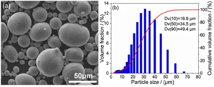
Spherical gas atomized Ti-40Al-9V-0.5Y (at.%) alloy powders with an average particle size of 34.5 μm were used as the starting material in SLM experiments, whose morphology and particle size distribution are presented in Fig. 1. The chemical composition (molar fraction, %) is: Ti 50.63%, Al 39.49%, V 9.38%, Y 0.5%.
Fig. 1. Ti-40Al-9V-0.5Y powders: (a) particle morphology, (b) particle size distribution.
The SLM experiments were carried out on a self-developed machine (LSNF-I), whose details can be acquired in our previous publication [10]. A series of single track with a length of 6 mm and cylinder samples with the size of Φ8 mm × 28 mm were deposited using the parameters listed in Table 1. Since scanning velocity plays a predominant role in solidification and cooling during SLM [14,16,17], it was chosen as the major variable while other parameters were kept constant in this work. All the SLM samples were built on pure Ti substrate in a high purity argon atmosphere (99.9%) to avoid the pick-up of reactive oxygen.
Table 1 Processing parameters applied in experiments.
| Parameters | Value |
|---|---|
| Laser power P (W) | 200 |
| Scanning velocity V (mm/s) | 100-1000, with a step of 100 |
| Hatch spacing S (mm) | 0.08 |
| Layer thickness δ (μm) | 50 |
| Phase angle (degree) | 90 |
During building, the cooling process of cylinder samples was recorded by a Phantom V2012 high-speed camera with Cavitar Cavilux HF illumination, whose frame rate and exposure time were 55000 fps and 1 μs, respectively. The solidification time of liquid-state molten pool (ts) was obtained by analyzing the video taken from a high-speed camera using a CV 3.1 software. Besides, the measure methods taking the scanning velocity of 200 mm/s as an example were exhibited in Fig. 2(a-d). In Fig. 2(a), the beginning time is designated as t0 when the laser melts powders at point A. At t0+14.71 ms in Fig. 2(b), point A is still in liquid state as the laser moves to point B. In Fig. 2(c), point A just solidifies at t0+22.79 ms. As time passes (at t0+26.94 ms in Fig. 2(d)), the solidified state of point A does not change. Therefore, the time in Fig. 2(c) (22.79 ms) can be defined as the solidification time (ts). For each condition, at least ten points are measured and averaged. The average ts under different scanning velocities are displayed in Table 2.
Fig. 2. Measure methods to determine the solidification time of liquid-state molten pools. (a) The laser melts powders at point A (t0); (b) point A is still in liquid state as the laser moves to point B at t0+14.71 ms; (c) point A just solidifies at t0+22.79 ms; (d) the solidified state of point A remains unchanged at t0+26.94 ms.
Table 2 The average ts under different scanning velocities.
| V (mm/s) | 100 | 200 | 300 | 400 | 500 | 600 | 700 | 800 | 900 | 1000 |
|---|---|---|---|---|---|---|---|---|---|---|
| ts (ms) | 39.75± 1.29 | 22.79 ± 5.35 | 3.53 ± 0.25 | 2.92± 0.13 | 2.49 ± 0.09 | 2.14 ± 0.07 | 1.26 ± 0.04 | 1.03 ± 0.06 | 0.70 ± 0.02 | 0.57 ± 0.05 |
Based on an image-analyzing ipwin32 software, the crack density defined as the length of crack in per square millimeter and the porosity defined as the ratio of the area of pores to the total area were evaluated by measuring six random optical micrographs. Metallurgical samples on vertical section were first ground, polished and etched with a modified Kroll’s solution (90 ml H2O, 2 ml HF and 8 ml HNO3), and then were observed by a Nikon Epiphot-300 optical microscope (OM) and an FEI Nova Nano 450 scanning electron microscope (SEM). The dimension of molten pool was determined by measuring six molten pools using an Image-Pro Plus 6.0 software. The distribution of elements was analyzed by an electron probe microanalyzer (EPMA-8050 G, Shimadzu). Phase identification was performed by X'Pert PRO X-ray diffraction (XRD) using a CuKα radiation with a step size of 0.02° and a dwell time of 1 s. Based on a Zeiss Gemini 300 SEM instrument equipped with a TSL/EDAX system, details on microstructure and phase characteristics were obtained by electron-backscatter-diffraction (EBSD) analysis. Samples for EBSD tests were electrolytic-polished in a mixture of perchloric acid and methanol (1:9, volume ratio) at -30 ℃ and 12 V. In addition, microhardness tests were carried out with a DHV-1000Z tester at a load of 500 g and a holding time of 20 s. Compression tests were performed for cylindrical samples (Φ6 mm × 9 mm) by the Shimadzu AG-100kN tester with a constant strain rate of 1 × 10⁻³ s-1 at room temperature. After compression, fracture morphologies were observed by SEM.
3.1.1. Process parameters
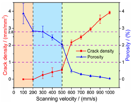
Fig. 3 displays the surface morphologies recorded by high-speed camera after completing a layer deposition and the micrographs on vertical section under different scanning velocities. Obviously, laser scanning velocity acts an important role in cracks and porosity of the SLM-processed Ti-40Al-9V-0.5Y alloy. The corresponding crack density and porosity are counted and shown in Fig. 4. An upward trend in crack density and a downtrend in porosity can be found with increasing scanning velocity from 100 to 1000 mm/s. Combining Fig. 3(a-f) with Fig. 4, the influence of scanning velocity on cracking sensitivity and porosity can be classified into three intervals based on different characteristics. When the scanning velocity ranges from 500 to 1000 mm/s (Fig. 3(c and f)), a large number of straight cracks appear nearly along the building direction (crack density >2 mm/mm2 in Fig. 4), accompanied with few pores (porosity<1% in Fig. 4). With the decrease of the scanning velocity (200 mm/s<V≤500 mm/s in Fig. 3(b and e)), the length and count of cracks decrease (crack density<1 mm/mm2), while the number of pores increases (2%< porosity≤2.8%). In contrast, when 100 mm/s≤V≤200 mm/s (Fig. 3(a and d)), no obvious cracks are found while the number of pores further increases (porosity>2.8%). Therefore, cracks can be reduced or even eliminated by decreasing scanning velocity when other parameters are fixed, but the porosity increases instead.
Fig. 3. Surface morphologies, metallographic photographs and molten pool characteristics of the cylinder samples deposited at different scanning velocities. (a, d, g) 100 mm/s≤V≤200 mm/s; (b, e, h) 200 mm/s<V≤500 mm/s; (c, f, i) 500 mm/s<V≤1000 mm/s. (Note that red dotted line represents the boundary of molten pool.).
Fig. 4. Crack density and porosity of SLM-processed samples deposited at different scanning velocities.
Fig. 3(g-i) show morphologies of the corresponding molten pools on vertical section at three intervals, respectively. Clearly, cracks propagate mainly along the center of molten pools (Fig. 3(h and i)), whereas spherical pores with diameters of 5-25 μm mainly distribute at the bottom of molten pools according to Fig. 3(g and h). Unexpectedly, pores are not the source of cracks, as displayed in Fig. 3(h).
3.1.2. Heat transfer mode of molten pool
Obviously, the morphology of molten pool has a significant impact on cracking sensitivity and porosity, as displayed in Fig. 3(g-i). That is, the morphology of molten pool experiences a transition from U-shape to V-shape with the decrease of the scanning velocity, which is advantageous to prevent cracking while easy to form pores. Further, the aspect ratios (depth-to-width ratios) of molten pools at different scanning velocities are given in Fig. 5. It can be seen that the aspect ratio gradually decreases with the increase of the scanning velocity from 100 to 1000 mm/s. As stated by Wei et al. [22], the varied characteristics of molten pools can be ascribed to the transformation of heat transfer mode during the formation of tracks. If energy input is high enough to produce severe metal evaporation and plasma, cavities can be generated in the molten pool due to the recoil plasma and vapor pressure, which induces a large aspect ratio and thus constitutes a keyhole mode. In contrast, the formation of molten pool mainly depends on heat conduction when the energy input weakens, thereby causing a relatively small aspect ratio and forming the conduction mode. In this work, for the given process parameters, the energy input declines with the increase of the scanning velocity, leading to a transition from keyhole to conduction mode.
Fig. 5. Aspect ratios of molten pools deposited at different scanning velocities (the insert displays the corresponding depth and width of molten pools).
King et al. [23] have proposed an empirical criteria that keyhole mode generates when the aspect ratio of molten pool attains to 0.5, which can be used to distinguish different heat transfer modes. From Fig. 5, the critical scanning velocity VK-C of SLM-processed Ti-40Al-9V-0.5Y alloy from keyhole to conduction mode is about 210 mm/s.
To further determine the critical value, a mathematical criterion to decide the threshold of keyhole mode was amended by Yang et al. [6], as shown in Eq. (1):
$\frac{P}{\sqrt{VD^{3}}}\ge \frac{KT_{b}\sqrt{\pi^{3}}}{A\sqrt{\alpha}}$ (1)
where K is the thermal conductivity of molten material, and α is the thermal diffusivity. The relationship between these two parameters is given by Eq. (2):
$\alpha=\frac{K}{\rho C}$ (2)
where ρ is the density, C is the specific heat capacity. Thus, Eq. (1) can be rewritten as follows:
$\sqrt{V}\le \frac{PA}{T_{b}\sqrt{K\rho C(\pi D)^{3}}}$ (3)
where A is the laser absorption coefficient of material, Tb is the boiling point, D is the laser spot size (100 μm), P and V are the laser power and scanning velocity, respectively. According to the thermo-physical properties of γ-TiAl alloy provided in Table 3, the threshold of scanning velocity is calculated to be about 201 mm/s, which is very close to the experimental result of VK-C.
Table 3 Thermal-physical properties of γ-TiAl alloy.
| Thermo-physical parameters | Value | Ref. |
|---|---|---|
| Density ρ (kg/m3) | 3800 | [24] |
| Thermal conductivity K (W·m-1·K-1) | 14.9 | [24] |
| Specific heat capacity C (J·kg-1·K-1) | 650 | [24] |
| Boiling point Tb (K) | 3315 | [6] |
| Laser absorption coefficient A | 0.25 | [25] |
As discussed above, it can be reasonably concluded that the molten pool belongs to keyhole mode when V≤200 mm/s, while belongs to conduction mode when V≥300 mm/s in this work. On one hand, due to the fact that more gases are captured in molten pools with large aspect ratios and cannot escape in time, the spherical pores are inclined to be formed. On the other hand, it is known that the molten pool with keyhole mode is often accompanied by “keyhole collapse” due to the competition among plasma, recoil vapor pressure, gravity and surface tension [22], and thus leading to the residual pores. Hence, the porosity of samples further increases at V≤200 mm/s compared with V>200 mm/s, as shown in Fig. 4.
In addition, by comparing the crack characteristics under two modes displayed in Fig. 3(g-i), we can draw a preliminary conclusion that the cracking sensitivity under "conduction mode" (V≥300 mm/s) is higher than "keyhole mode" (V≤200 mm/s) during SLM processing Ti-40Al-9V-0.5Y alloy. Meanwhile, it was verified that different heat transfer modes will determine the distinct cooling rate in molten pools [6]. Therefore, to further explore the relationship between heat transfer mode and cracking sensitivity, the cooling rate in molten pools under two modes is investigated.
3.1.3. Cooling rate in molten pools
In the laser processing, an analytical and approximate method to evaluate cooling rate $\dot{T}$ x,t) in the molten pool during rapid solidification and cooling has been conceived based on the Eq. (4) [26]:
$\dot{T}(x,t)=\partial T/\partial t=\frac{q_{0}}{K}\left[\sqrt{\frac{\alpha}{\pi t}}e^{-(\frac{x}{\sqrt{4\alpha t}})^{2}}-\sqrt{\frac{\alpha}{\pi t_{S}}}e^{-(\frac{x}{\sqrt{4\alpha t_{S}}})^{2}}\right]$ (4)
where ∂T/∂t is the first-order partial derivative of the temperature T versus time t, K is the thermal conductivity, α is the thermal diffusivity, and x is the depth beneath the surface (μm). For simplicity, only the cooling rate on the surface of powder bed (x = 0) is considered in this work. So Eq. (4) can be simplified to:
$\dot{T}(t)=\frac{q_{0}}{K}\left[\sqrt{\frac{\alpha}{\pi t}}-\sqrt{\frac{\alpha}{\pi t_{S}}}\right]$ (5)
where ts is the solidification time of liquid-state molten pool summarized in Table 2. t is the total time (t=ti+ts). ti is the interaction time between laser and powders (heating time), which can be given as follows [6]:
$t_{i}=\frac{D}{V}$ (6)
where D is the laser spot size, and V is the scanning velocity. Moreover, q0 is the energy density flux of laser beam with surface absorption (W/μm2), which obeys the Gaussian distribution and can be expressed as Eq. (7) [27]:
$q_{0}=\frac{2AP}{\pi R^{2}}\exp(\frac{-2r^{2}}{R^{2}})$ (7)
where A is the laser absorption coefficient, P is the laser power, R is the radius of laser beam (50 μm), and r is the radial distance from a point on the powder bed surface to the center of laser beam (μm). Combining Eqs. (5), (6), (7), the cooling rate during SLM can be remodeled as follows:
$\dot{T}=\frac{2AP}{\pi R^{2}K}\left[\sqrt{\frac{\alpha}{\pi (\frac{D}{V}+t_{S})}}-\sqrt{\frac{\alpha}{\pi t_{S}}}\right]\exp(\frac{-2r^{2}}{R^{2}})$ (8)
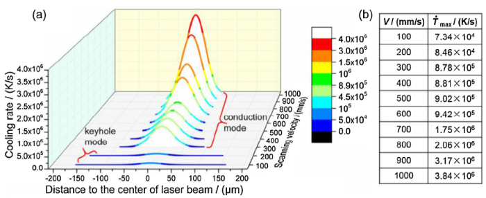
From the thermal-physical properties of γ-TiAl alloy listed in Table 3, the cooling rates in molten pools are calculated based on Eq. (8) and presented in Fig. 6. It is clear that the cooling rate in molten pool at each scanning velocity is approximately "Normal Distribution", which reaches to the maximum in the center of molten pool and then gradually decreases from center to boundary, as similarly reported by Li et al [7]. Additionally, the cooling rate at the same distance to the center of molten pool increases as the scanning velocity increasing from 100 to 1000 mm/s. Meanwhile, it is found from Fig. 6(b) that the cooling rate in the center of molten pool ($\dot{T}_{max}$) is smaller than or equal to 8.46 × 10⁴ K/s when V≤200 mm/s while is higher than or equal to 8.78 × 10⁵ K/s when V≥300 mm/s. Evidently, the calculated cooling rates under conduction mode (V≥300 mm/s) are at least one order of magnitude larger than those of keyhole mode (V≤200 mm/s), which is likely to induce cracks for the low ductility Ti-40Al-9V-0.5Y alloy.
Fig. 6. Cooling rates in molten pools under different scanning velocities. ($\dot{T}_{max}$: the cooling rate in the center of molten pool.).
According to the above results and analysis, it is easy to declare that the effects of process parameters on cracking sensitivity are highly dependent on the cooling rate in molten pool with different heat transfer modes. The keyhole mode with slower cooling rates has a lower cracking sensitivity in comparison to the conduction mode.
As is well known, the cooling rate has a direct impact on microstructure formation and phase transformation [6,28], which is favorable to explore the cracking behavior and crack inhibition mechanism. Hence, microstructure characteristics and phase transformations for the cracking sample at 300 mm/s and crack-free sample at 200 mm/s were compared in detail.
3.2.1. Microstructure characteristics
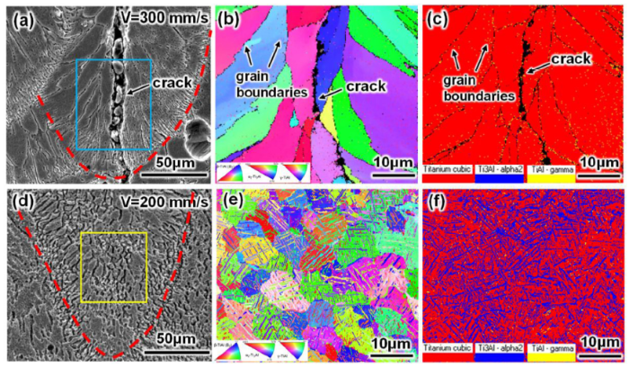
Fig. 7 shows the microstructure and phase characteristics of the cracking and crack-free samples. Clearly, the substantial differences for microstructure can be observed. In Fig. 7(a and b), for the cracking sample, the coarse columnar grains (with length≥40 μm and width≥10 μm) grow epitaxially from the boundary to center in the molten pool under conduction mode. It can be easily found that cracks prefer to form along grain boundaries in the center of molten pool. In contrast, as displayed in Fig. 7(d and e), fine equiaxed microstructures (3-10 μm in width) of the crack-free sample are produced in the center of molten pool under keyhole mode.
Fig. 7. Microstructures and phase characteristics of molten pools for cracking and crack-free samples. (a, d) SEM images (red dotted line represents the boundary of molten pool); (b, e) Inverse pole figures (IPFs) for zones marked by the blue and yellow rectangles, respectively; (c, f) phase maps corresponding to b and e, respectively. (Note that red, blue, and yellow represents the B2, α2 and γ phases, respectively.).
3.2.2. Phase composition
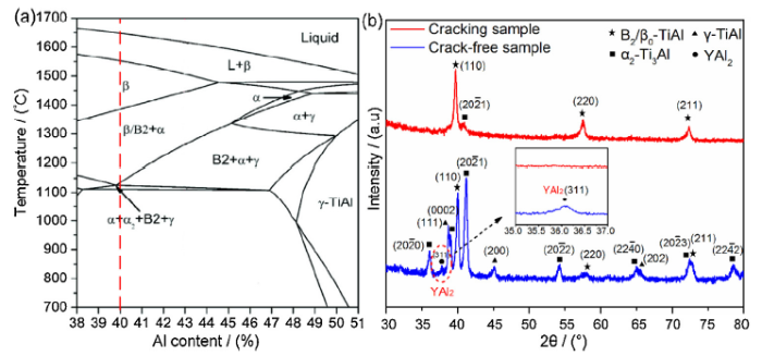
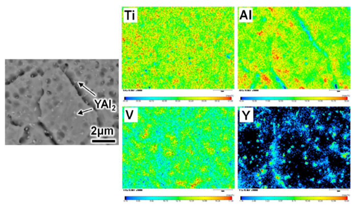
Fig. 8a displays the Ti-Al binary phase diagram [29], and the red dotted line shows the solidification path of Ti-40Al. Evidently, the phase transformation of Ti-40Al alloy includes a decomposition reaction β→α, two eutectoid reactions α→α2-Ti3Al+γ-TiAl and α2→α2+γ, two ordering reactions α→α2 and β→B2 (β0-TiAl) [30]. Moreover, the reaction Y+2Al→YAl2 will occur for TiAl-based alloys containing the element of Y [31]. Fig. 8(b) shows XRD analysis results of the cracking and crack-free samples. From Figs. 7(c) and 8(b), it is found that B2 phase (> 99%) tends to dominate in the cracking sample. While other phases including α2, γ and YAl2 are hardly detected due to much lower fractions. On the contrary, from Figs. 7(f) and 8(b), the content of B2 phase (22.2-34.5%) greatly decreases, while those of α2 phase (62.9-70.3%), γ phase (3.34-7.53%) and YAl2 phase (2.58-3.52%) increase for the crack-free sample. Besides, from the element distribution maps of fine equiaxed microstructures shown in Fig. 9, the Y-rich YAl2 phase with small ellipsoid structure (50-300 nm) forms along the grain boundaries and within grains. It should be mentioned that YAl2 phase is too small to be detected by EBSD. Moreover, acicular and platelet α2 phases uniformly distribute inside the equiaxed grains (B2 matrix) (Fig. 7(e and f)).
Fig. 8. (a) Section of Ti-Al binary phase diagram (the red dotted line shows the solidification path of Ti-40Al); (b) XRD spectra of the crack-free and cracking cylinder samples.
Fig. 9. EPMA maps of element distribution for the crack-free sample.
3.2.3. Cracking behavior
3.2.3.1. Solidification cracking
During liquid-state solidification, the center of molten pool is the final stage of solidification due to heat flux flows from boundary to center [7]. Besides, the cooling rate in the center of molten pool is the maximum and attains to 8.78 × 10⁵ K/s at 300 mm/s. Thus, solidification shrinkage in volume and thermal contraction results in large residual tensile stresses in the center as temperature and liquid volume fraction decrease. Meanwhile, lack of liquid feeding in the center leads to the formation of fragile thin films at columnar grain boundaries. In this case, the fragile thin films will be easily torn by residual tensile stresses to form solidification cracks. Similar finding was reported by Martin et al. [11]. Cracks mainly propagate along boundaries of coarse columnar grains in the center of molten pool under conduction mode, and thus spanning multiple columnar grains (Fig. 7(a and b)). As a consequence, the coarse columnar grain is the primary factor for solidification cracking at the final stage of solidification during SLM processing Ti-40Al-9V-0.5Y alloys.
3.2.3.2. Cold cracking
Subsequent to the solidification, solid-state transformation will take place. Due to the higher cooling rate ($\dot{T}_{max}$ =8.78 × 10⁵ K/s) at 300 mm/s, the diffusion-controlled phase transformations of β→α, α→α2+γ and α2→α2+γ are restricted, which is similar to the report by Mayer et al. [32]. Besides, since the strong β-stabilizing element of V is concentrated in prior-β phase and is hard to diffuse under higher cooling rate, the prior-β phase cannot be decomposed until the disorder-order transformation β→B2 is triggered. Consequently, the ordered B2 phase is retained at room temperature and dominates in samples. Notably, B2 phase was proved to be much harder and more brittle than α2 and γ phases at low temperatures (B2 > α2 > γ) [7,30], which greatly reduces the ductility of this alloy. Therefore, cold cracks are easy to form under the combination of dominant brittle B2 phase and large residual stresses during solid-state cooling. Similar finding was reported in the electron beam welding of forged Ti-43Al-9V-0.3Y plates [33]. As mentioned above, the residual tensile stress in the center of molten pool is the maximum due to the highest cooling rate. Hence, cold cracks further propagate along grain boundaries in the center of molten pool where solidification cracks have occurred, and eventually penetrate multiple molten pools nearly along the building direction (Fig. 3(e-f and h-i)).
3.2.4. Crack inhibition mechanism
3.2.4.1. Inhibition of solidification cracking
As illustrated by Gu et al. [28], the dynamic viscosity μ of liquid within molten pool depends on temperature T and can be assessed by Eq. (9):
$\mu=\frac{16}{15}\sqrt{\frac{m}{k_{B}T}}\lambda$ (9)
where m is the atomic mass, λ is the surface tension of liquid, and kB is the Boltzmann constant. The slower cooling rate ($\dot{T}_{max}$=8.46 × 10⁴ K/s) at 200 mm/s leads to a longer laser irradiation time on powders and a higher heat input into the molten pool, thereby enhancing the operative temperature T. Meanwhile, the dynamic viscosity μ accordingly decreases based on Eq. (9). The combined effect of a long liquid lifetime and a low dynamic viscosity is beneficial to promote melt flow and reduces solidification shrinkage tension [34]. In this case, enough liquid can assure liquid reflux and backfill in the center. Moreover, the temperature gradient in molten pool can be reduced markedly, which was also reported by Gu et al. [28]. Thus, compared with conduction mode, an energetically favorable condition for nucleation of equiaxed grains can be generated in the center of molten pool under keyhole mode.
Additionally, the slower cooling rate is favorable to the diffusion of atoms and provides more time to eject Y atoms into the liquid from the growing solid, the YAl2 particles will form along the solidification front where large numbers of Al atoms are present during solidification [35]. As clarified by Chen et al. [31], there is a strong binding force between Y and Al atoms to form YAl2 phase. The fine and dispersed YAl2 particles may act as ideal low-energy-barrier heterogeneous nuclei in solidification front and result in grain refinement. Similar finding has been reported in as-cast Ti-43Al-9V-0.2Y (at.%) [35] and Ti-47Al-(0.1-1)Y (at.%) [36] alloys. Besides, these heterogeneous nucleation sites will reduce the critical amount of undercooling required to induce the growth of equiaxed grains [11].
Based on a favorable condition and additional heterogeneous nuclei, the fine equiaxed microstructures tend to be developed in the center of molten pool. It is generally known that fine equiaxed structures in semi-solid allow easier grain rotation and deformation [11], providing a means to accommodate thermal contraction strain and thus preventing the initiation of solidification cracks. Moreover, since the fine equiaxed grains can greatly increase the number of grain boundaries, the growth of cracks is hindered by the grain boundaries even if cracks have formed [37,38].
3.2.4.2. Inhibition of cold cracking
During subsequent solid-state transformations, atoms can diffuse in short-range under the reduced cooling rate ($\dot{T}_{max}$ =8.46 × 10⁴ K/s) at 200 mm/s. The displacive martensitic transformation β→α2 will occur, which was also found in as-cast Ti-(38-42) Al-(5-10) V (at.%) and Ti-44.58Al-3.23Mo-0.12B (at.%) alloys after water quenching from single β-phase field [32,39,40]. Besides, partial eutectoid reaction α2→α2+γ and disorder-order transformation β→B2 will occur, as declared in Refs. [15,30]. To further explain above phase transformations for the crack-free sample, the pole figures (PFs) of B2, α2 and γ phases corresponding to the zones marked by the yellow rectangle in Fig. 7(d) are given in Fig. 10. There are coincident points (points 1 and 2) in pole figures 110B2 and 0001α2, and coincident points (points 3 and 4) in 111B2 and 11$\bar{2}$0α2 (Fig. 10(a and b)). Also, some marked points in pole figures belonging to 0001α2 (points 1 and 5) and 11$\bar{2}$0α2 (points 3 and 6) overlap with points in 111γ and 110γ, respectively (Fig. 10(b and c)). Therefore, classic Burgers orientation relationship (OR) from β/B2 to α2 phase, i.e. 110B2// 0001α2 and 111B2// 11$\bar{2}$0α2 [7] can be determined. The classic Blackburn OR from α2 to γ phase, i.e. 0001α2// 111γ and 11$\bar{2}$0α2// 110γ [40] can also be identified in crack-free Ti-40Al-9V-0.5Y samples.
Fig. 10. Pole figures (PFs) corresponding to the zones marked by the yellow rectangle in
Consequently, for the crack-free sample, a large number of supersaturated α2 phases and a small number of global γ phases are obtained due to the decomposition of brittle B2 phase. The combination of fine equiaxed grains and reduced content of brittle B2 phase contributes to improving the ductility of Ti-40Al-9V-0.5Y alloy. Moreover, residual stress can be reduced greatly under slower cooling rates. Therefore, cold cracks can be suppressed when the accumulated strain cannot overtake the enhanced ductility of Ti-40Al-9V-0.5Y alloy during solid-state cooling.
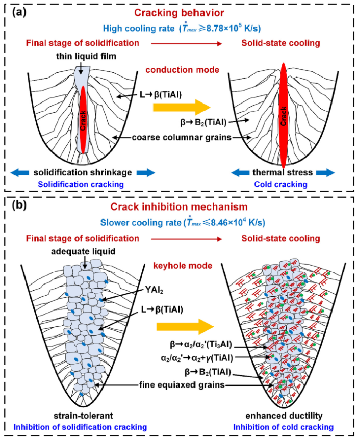
Based on the above experimental results and analysis, the schematic illustration of cracking behavior and crack inhibition mechanism during SLM processing Ti-40Al-9V-0.5Y alloy are exhibited in Fig. 11. According to Fig. 11(a), under conduction mode with high cooling rates ($\dot{T}_{max}$≥8.78 × 10⁵ K/s), solidification cracking will occur at the final stage of solidification because of coarse columnar grains, and then cold cracking will occur during solid-state cooling due to the dominant brittle B2 phase. Both cracks mainly propagate along fragile grain boundaries in the center of molten pool. Accordingly, this two kinds of cracks can be inhibited by the combination of fine equiaxed grains and reduced content of brittle B2 phase under keyhole mode with slower cooling rates ($\dot{T}_{max}$≤8.46 × 10⁴ K/s), as shown in Fig. 11(b).
Fig. 11. Schematic illustration of cracking behavior and crack inhibition mechanism for SLM-processed Ti-40Al-9V-0.5Y alloy.
In summary, for a β-solidifying γ-TiAl alloy containing β-stabilizing elements like V, Nb, Mo, etc. (promoting the formation of B2 phase) and grain refinement elements like Y, B, C, etc. (promoting the formation of fine equiaxed grains), the effect of cooling rate on solidified microstructure and phase evolution determines the cracking sensitivity during SLM. In other words, microstructure characteristics and phase transformations controlled by cooling rate decide the inherent ductility of β-solidifying γ-TiAl alloys. The coarse columnar grains and dominant brittle B2 phase at high cooling rates result in a drop in ductility to a very low level, which is extremely prone to cracking. In contrast, the fine equiaxed grains and reduced content of brittle B2 phase at slower cooling rates greatly improve the ductility and thus can effectively prevent cracks.
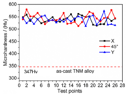
To further evaluate mechanical properties of the SLM-processed Ti-40Al-9V-0.5Y alloy, microhardness and room-temperature compression properties of the crack-free sample at 200 mm/s were investigated. For comparison, corresponding data of as-cast and SLM-processed β-solidifying TNM (Ti-43.5Al-4Nb-1Mo-0.1B at.%) alloys are also given [18,41]. It is known that the TNM alloy is a typical β-solidifying γ-TiAl alloy widely researched and used. Fig. 12 gives the microhardness distribution in the directions of X, Y and 45°on vertical section for the crack-free sample. It is evident that the microhardness shows directional independent. Actually, the uniformity of microhardness is primarily attributed to the homogeneity of fine equiaxed microstructure (Fig.7(d and e)). Moreover, the average microhardness is measured to be 542 ± 19 Hv and is far beyond that of as-cast TNM alloy (347 ± 5 Hv) [41].
Fig. 12. Microhardness distributions in the directions of X, Y and 45° for the crack-free sample deposited at 200 mm/s.
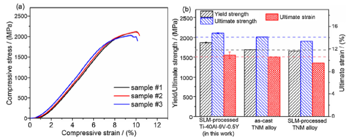
The compression stress-strain curves of the three crack-free Ti-40Al-9V-0.5Y samples at 200 mm/s are depicted in Fig. 13(a). Fig. 13(b) summarizes the compression properties of the crack-free Ti-40Al-9V-0.5Y alloy, the as-cast and SLM-processed TNM alloys. It can be found that the average yield strength, ultimate strength and ultimate compressive strain are 1871 ± 12 MPa, 2106 ± 13 MPa and 10.89 ± 0.57%, respectively, which surpasses those of as-cast and SLM-processed TNM alloys [18]. According to the Hall-Petch formula, the strengthening mechanism can be firstly ascribed to the finer equiaxed microstructures of the SLM-processed Ti-40Al-9V-0.5Y alloy (3-10 μm) in comparison to as-cast and SLM-processed TNM alloys (˜18 μm and ˜50 μm, respectively) [18]. Moreover, small YAl2 precipitates dispersed within grains and at grain boundaries may impede the movement of dislocations and lead to the pile-up of dislocations, as declared by Li et al. [36]. Thus, precipitation strengthening also plays an important role in improving compression strengths. Furthermore, strain can be accommodated more readily in the fine equiaxed microstructures [11], which is beneficial to get better plasticity for SLM-processed Ti-40Al-9V-0.5Y samples.
Fig. 13. (a) Compression stress-strain curves of the three crack-free Ti-40Al-9V-0.5Y samples at 200 mm/s. (b) Compression properties of the crack-free SLM-processed Ti-40Al-9V-0.5Y alloy, the as-cast and SLM-processed TNM alloys.
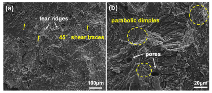
Fig. 14 shows the corresponding fracture surface of the compression sample. In Fig. 14(a), a large number of near 45° shear tracks (as marked by yellow arrows) and tear ridges (as marked by white arrows) appear, which is mainly due to the competition between normal stress and shear stress [42]. At a high magnification (Fig. 14(b)), a small number of dimples with parabolic shape (as marked by yellow dotted ellipses) are found because of small grain sizes. Similar finding was reported by Fang et al. [43]. Therefore, the fracture mode is quasi-cleavage fracture for SLM-processed Ti-40Al-9V-0.5Y alloy. Meanwhile, some spherical pores pointed by white arrows in Fig. 14(b) can be observed, which may induce the formation of cracks on straining and limit the further improvement of compressive properties.
Fig. 14. SEM images of compression fracture surface for the crack-free sample at (a) a low magnification, and (b) a high magnification.
SLM has been used to fabricate a β-solidifying Ti-40Al-9V-0.5Y alloy with a high cracking sensitivity. The influence factors for cracking sensitivity, cracking behavior and crack inhibition mechanism as well as mechanical properties of the crack-free sample were investigated. The following conclusions can be drawn.
(1) The effects of process parameters on cracking sensitivity primarily depend on the cooling rate in molten pool with different heat transfer modes. The keyhole mode with slower cooling rates has a lower cracking sensitivity than conduction mode.
(2) Microstructure characteristics and phase transformations controlled by cooling rate determine the inherent ductility of β-solidifying γ-TiAl alloys. The coarse columnar grains and dominant brittle B2 phase at high cooling rates result in a significant drop in ductility, and thus to induce solidification cracking and cold cracking, respectively. While the fine equiaxed grains and reduced content of brittle B2 phase at slower cooling rates greatly improve the ductility and thus can effectively prevent this two kinds of cracks.
(3) For the crack-free Ti-40Al-9V-0.5Y sample produced by SLM, the microhardness is directional independent with an average microhardness of 542 ± 19 Hv. The room-temperature compression properties are superior to those of as-cast and SLM-processed β-solidifying TNM alloys. The strengthening mechanism can be attributed to grain refinement and precipitation strengthening.
This work was supported financially by the Pre-research Fund Project of Ministry of Equipment and Development of China (No. 61409230301), and the Fundamental Research Funds for the Central Universities through Program no.2019kfyXMPY005 and no.2019kfyXKJC042. The authors would like to thank the Analytical and Testing Center and the State Key Laboratory of Materials Processing and Die & Mould Technology of HUST.

 WeChat
/
| 〈 |
|
〉 |


