Search for articles:
C. Garcia-Cabezon , C. Garcia-Hernandez
Corresponding authors:
Received: 2018-12-13
Revised: 2019-03-15
Accepted: 2019-05-17
Online: 2020-01-15
Copyright: 2020 Editorial board of Journal of Materials Science & Technology Copyright reserved, Editorial board of Journal of Materials Science & Technology
More
Abstract
In this work, a method to improve the protection against corrosion of porous sintered stainless steel is presented. It is based on the electrodeposition of polypyrrole (PPy) layers doped with a large size counterion such as dodecylbenzenesulphonic acid (DBSA), a conducting polymer with high corrosion resistance and good biocompatibility. The efficacy of PPy coating depends on the adequate adhesion between the metal substrate and the coating layer. The protection against corrosion has been tested using 316 L stainless steel (SS) powder sintered at different conditions to evaluate the effect of the sintering atmosphere (nitrogen and vacuum) and cooling rates (furnace and water) on corrosion resistance, while wrought 316 L SS has been used as reference material. In addition, two electrochemical deposition techniques have been tested to select the most adequate. Open circuit potential evolution, anodic polarization measurements and electrochemical impedance spectra have been used to evaluate corrosion protection in phosphate buffer saline medium. It has been evidenced that a more homogeneous and stable coating was obtained in the case of porous stainless steel. The corrosion potential shifted to nobler values and the anodic polarization branch became more stable. Coated porous samples have a good passivation performance with a lower stable passive current density and a higher breakdown potential. The transfer electronic resistance and the impedance module increase more than one order of magnitude. Therefore, the porosity of sintered stainless steel is seen as an advantage for the improvement of the adherence of the PPy coatings. The best corrosion protection is found for samples sintered in nitrogen and water-cooled.
Keywords:
The powder metallurgy (PM) technique can currently be used to obtain materials with controlled porosity. This processing provides a feasible and economic manufacturing of complex shape austenitic stainless steel (SS) components with such advantages as acceptable mechanical properties, good dimensional precision, and high surface finish. The porous austenitic SS obtained by PM is considered as a very attractive biomaterial. These steels, used for metallic implants, are characterized by good mechanical properties, easy fabrication and low cost as compared to other biomaterials such as titanium or cobalt alloys; but their corrosion resistance in body fluids is relatively low as compared to its equivalent wrought SS [1]. Furthermore, the use of SS processed by PM for prosthetic joints enhances wear resistance thanks to the lubrication [2]. Moreover, pores in SS components improve bone fixation by reducing the difference between the elastic module of the implant and the surrounding bone [[3],[4]]. Despite all these advantages, there is an important problem for porous SS as biomaterial, i.e., their corrosion resistance. It decreases as porosity increases [5] as a result of the crevice corrosion, the poorer passive film stability and formation, and the increase in the area exposed to the corrosion media [[6],[7]]. It is then very relevant to find solutions to this problem.
Porous 316 L SS has been used for biomedical applications [8], though wrought steel showed a better corrosion performance owing to the absence of porosity. The porosity can be minimized by the control of the compaction pressure and the sintering step. This allows 316 L SS to be obtained with the functional properties required for successful implantation in the human body [9]. However, by using conventional PM techniques, it is very difficult to get porosity under 10%, so the corrosion behavior of sintered 316 L SS is always worse than that of its equivalent wrought 316 L SS [[10],[11]].
One way to solve these problems, and at the same time reduce the exposed area, is to use protective coatings. It has been proven that surface treatments with noble metals, ceramics or plastics play an important role in the corrosion protection of SS for orthopaedic applications [12]. Metallic coating combined with oxide surface treatment of the SS had a positive effect on the improvement of corrosion in physiological solutions [13]. As for plastic coating, for many years now, conductive polymers have been selected as candidates for active and passive protection against corrosion in industrial environments [[14], [15], [16]]; this strategy has not yet been explored for PM materials. In the last few years, there has been increasing interest in the anti-corrosion activity of such conductive polymers as polyaniline (PANI) and PPy, as they can easily be produced by both chemical and electrochemical techniques (galvanostatic, potentiostatic and cycle voltammetry methods) [[17], [18], [19], [20], [21], [22]]. The conducting polymers for corrosion protection is a topic of current controversy; it may have excellent protection or may lead to an enhancement of the attack, depending on the deposition conditions. Conducting polymers constitute a physical barrier against attack from the corrosive medium and can act as an inhibitor, stabilizing the formation of the passive film [[23],[24]]. In the case of SS, the enhancement of oxides rather than hydroxides in the formation of a stable passive film improves the corrosion resistance [25]. Another proposed corrosion mechanism is the intelligent release of inhibitor anions and their relation with the presence of large defects [26]. So, the anticorrosion properties of conducting polymers, such as PEDOT:PSS, as inhibitors in epoxy coating were proven [27].
The corrosion properties depend on the structural and electronic characteristics of the materials, which are related to such conditions of synthesis as the electrochemical technique [[24],[25]], the substrate, the electrolyte, the dopant, the temperature, etc [[26], [27], [28], [29], [30], [31]]. Concerning this study, the polymer PPy has been used for many reasons: its high resistance to corrosion and delamination, facile synthesis, high conductivity, good adhesion, good biocompatibility and good redox properties [32]. Concerning the dopant, the DBSA was selected taking into account the fact that it is a large and immobile anion that shows cation exchange properties and forms micelles that attract cations and repel anions [33] in a copper substrate. PPy doped with DBSA has also been successfully deposited on SS as a protective coating against corrosion in hydrochloric acid [34].
Recent studies show that the electropolymerization temperature [35] and the deposition potential [36] affect the morphology of the deposited PPy films on steel and modify their anti-corrosion performance. In addition, their efficiency as inhibitors depends on their adsorption on the metal surface. The self-assembled monolayers with pyrrol have been successfully used as adhesion promoters, inducing a faster electropolymerization with a more stable polymer coating that enhances corrosion resistance [37]. Most of the referenced works have been done on conventional steels obtained by mouldings or plastic deformation. In this study, sintered austenitic SS has been selected as the substrate to verify the effect of porosity on the adhesion of these coatings. Two electrochemical deposition techniques were tested to select the most adequate.
Conducting polymers have been widely used in biomedical applications due to their conductivity, compatibility and low-cost processing. In addition, compared with traditional metal or semiconductor materials, conducting polymers show better biocompatibility [[38],[39]]. PPy and PANI coatings are often investigated as they can give high corrosion protection to SS in different environments, such as acid solutions [[40],[41]], chloride media [[42],[43]], or artificial sea water [44]. However, little work on biological media appears in the bibliography [[45], [46], [47]] and most of them are nanocomposites. In this study, PBS (phosphate buffer saline) at 37 °C and pH 7.4 was chosen as the electrolyte for the electrochemical testing. It is a suitable physiological environment to evaluate the corrosion in biological applications. It simulates the ionic strength of the human blood, its pH and its buffering capacity. No studies have been found related with the application of these coatings to porous materials in simulated body fluid. It should also be understood that the inherent porosity of PM SS should be an advantage for the adhesion of these coatings.
Thus, the main issue of this work is to show a comparative study of corrosion resistance of PPy coatings using several electrochemical conditions on 316 L SS, sintered in different conditions and using electrochemical techniques (open circuit potential, anodic polarization measurement and impedance spectroscopy) in a PBS solution. The effects of porosity and sintering conditions are evaluated using wrought 316 L SS as the non-porous reference material.
Water atomized austenitic 316 L SS powder (HÖGANÄS, Belgium) with apparent density 2.87 g/cm3, flow rate 25 s/50 g and nominal particle size <150 μm, was used in this work, and commercial wrought austenitic 316 L SS (Acerinox, Spain) was used on a comparative basis, see Table 1. To find identical chemical compositions was not possible. Nevertheless, these two materials are very similar. The nitrogen content in the powder will increase during the process of sintering in a nitrogen-hydrogen atmosphere.
Table 1 Chemical composition (wt%) of water atomized austenitic 316 L SS powder and wrought AISI 316 L.
| C | Cr | Ni | Mo | Mn | Si | Cu | N | Fe | |
|---|---|---|---|---|---|---|---|---|---|
| Powder | 0.021 | 16.10 | 13.55 | 2.24 | 0.20 | 0.87 | 0.02 | - | Bal. |
| Wrought | 0.040 | 17.32 | 10.85 | 2.00 | 1.36 | 0.34 | 0.33 | 0.034 | Bal. |
Disc specimens (12 mm in diameter and 6 mm in height) were uniaxially compacted at 750 MPa for 300 s using a floating die and zinc stearate as die lubricant. Heating at 5 °C/min and sintering at 1250 °C in N2-H2 (95%‒5%) for 60 min was selected [31]. In addition, for comparative purposes, some samples were sintered in a vacuum at 1250 °C for 60 min at low vacuum (pressure = 11 Pa). No chromium losses occurred since the chemical composition was identical before and after sintering. For samples sintered in a nitrogen atmosphere, two different cooling processes were introduced [48]. Some samples were cooled in the furnace at a slow rate of 5 °C/min (referred to from now on as the “furnace-cooling” process), while the others were subjected to fast cooling by direct immersion in water from the sintering oven (designated from now on as the “water-cooling” process) [48]. Samples sintered in a vacuum were only cooled in the furnace; the water-cooling process is not advisable because of strong oxidation problems. The samples are referred to as “nitrogen-furnace-cooled” (NFC), “nitrogen-water-cooled” (NWC), and “vacuum-furnace-cooled” (VFC), respectively. Wrought SS is referred to as WSS.
Archimedes’ method of water immersion was applied to measure the density of the sintered specimens. The degree of porosity was determined by image analysis. Optical microscopy was used to observe the microstructure of the specimens etched by Vilella´s at ambient temperature for 30 s. Electrochemical etching with 10% oxalic acid for 90 s at 1 A/cm2 helped to define both the rate and location of chromium carbide precipitation.
Electropolymerizations over the samples were carried out at room temperature in an EG&G Parstat 273A potentiostat/galvanostat, using a three-electrode configuration. The same instrument was used for the corrosion tests.
The auxiliary electrode was a conventional platinum wire. The reference electrode was an Ag/AgCl electrode in a 3 mol/L KCl solution. SS samples were used as working electrodes. Samples were polished with 0.3 μm alumina suspension and rinsed with deionized water in an ultrasonic bath.
The PPy films were obtained by electropolymerization from a solution containing 0.1 mol/L pyrrole and 0.05 mol/L DBSA as dopant [42]. Two electrochemical techniques: chrono-potentiometry (CP) or galvanostatic polarizatión, at a current density of 0.02 mA/mm2 for 800 s, and chrono-amperometry (CA) or potentiostic polarization, at a constant potential of 0.8 VAg/AgCl for 800 s, were used [49]. Films were deposited on the surfaces of PM and wrought SS. An SEM-FEI (QUANTA 200 F) was used to register the images of the electrodes’ surface characteristics. Samples with a PPy coating are designated, from now on, as the original name plus the suffix ‘-PPy’. For example, the water-cooled sample sintered in nitrogen (NWC) with a PPy coating is designated as NWC-PPy.
To assess the adhesion of the electrodeposited coating, a peeling test ASTM D 3359, method A [50], was carried out. The test consisted in making two cuts in the film that intersected near their middle with a small angle (30° and 45°), then a scotch tape was pressed to the scratched sample for 60 s and removed and the X-cut area was checked for removal of coating from the substrate.
Electrochemical corrosion measurements were carried out in the simulated body fluid PBS solution (0.8 g/l NaCl, 0.2 g/l KCl, 0.594 g/l Na2HPO4, 0.2 g/l KH2PO4) at a temperature of 37 °C ± 1 °C. A saturated calomel electrode (SCE) was used as the reference electrode. The electrochemical methods included open circuit potential (OCP) for 360 h, potentiodynamic anodic polarization measurements, and electrochemical impedance spectroscopy (EIS).
The potentiodynamic anodic polarization curves were performed following ASTM standard G-5 [51]. Surface preparation of the samples was performed with 1 μm of diamond paste polishing. Nitrogen streaming and agitation were used throughout the whole test. The experimental test procedure was as follows: first, a 5 min delay at open circuit (OC) potential followed by a 2 min anodic attack at -220 mVSCE; then a delay of 2 min at VOC, a 1 min cathodic cleaning at -600 mVSCE, a 5 min delay at OC potential and finally an anodic potentiodynamic scan, which started at 50 mVSCE below VOC, reaching 1000 mVSCE. The scan rate was set at 50 mV/min [46]. The surfaces after polarization were observed with an optical microscope.
The corrosion rate was determined using Tafel’s extrapolation methods. Tafel’s cathodic and anodic slopes, the corrosion potentials and the corrosion current densities were estimated from the Tafel plots.
EIS was performed in a PBS solution at 37 °C ± 1 °C, with a frequency range from 1 MHz to 0.01 Hz and a signal amplitude of 10 mV at open circuit potential, after a stabilization step at open circuit for 1800 h. A Solartron 1260A Impedance/Gain-phase analyser was used in these experiments.
All tests were performed at least three times for each condition and there were no significant differences between results. The coefficients of variation between these tests are less than 5% for the three techniques used.
A full microstructure description of PM 316 L SS samples can be found elsewhere [[46],[50]]. Here, the most remarkable microstructural features are outlined.
Table 2 shows the density and porosity of the samples. Prior works had proven that compaction pressure was the main parameter affecting porosity and that there were significant differences between WC and FC samples [[48],[52]]. For nitrogen sintered materials, water-cooling provided denser samples than furnace-cooling.
Table 2 Densities and degree of porosity of the 316 L SS samples as a function of the sintering atmosphere and of cooling rate.
| Sample | Sintering density (g/cm3) | Porosity (%) |
|---|---|---|
| NFC | 6.77 | 13.00 |
| NWC | 7.20 | 11.20 |
| VFC | 6.90 | 11.94 |
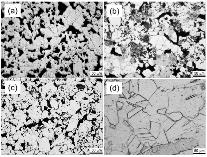
VFC consisted of heterogeneous and fine grain austenite, with a low amount of globular particles dispersed in the matrix, identified as oxides (Fig. 1(a)). The microstructure of NFC (Fig. 1(b)) consisted of two constituents. A ‘lamellar constituent’ formed by lamellae of chromium precipitates in chromium depleted matrix [[48],[53]] and austenite in a large proportion were identified. The cell morphology of the lamellar constituent has been described elsewhere [[54],[55]]. Furthermore, a slight transgranular and large intergranular chromium nitride/carbonitride precipitation was observed. On the contrary, for NWC, a more homogeneous structure was seen; no precipitation of chromium nitrides/carbonitrides were detected (Fig. 1(c)). A single phase with twin grains was identified as the austenite phase. Typical austenite with some delta-ferrite bands can be observed for WSS (Fig. 1(d)).
Fig. 1. Microstructures after electrochemical etching with 10% oxalic acid of (a) VFC, (b) NFC, (c) NWC and (d) WSS.
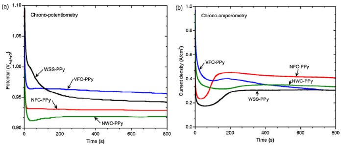
The electropolymerization of pyrrole on every sample was generated under CP or CA conditions, always resulting in the formation of samples with the deposited PPy layer. Fig. 2(a) shows the potential vs time curves registered during the electrodeposition of PPy films using a CP process. As expected, a sharp decrease in the potential was observed as the current pulse was applied. It is usually assumed that the initial high potential in constant current polarization is due to nucleation overpotential in the PPy polymerization process. The following decrease in potential is due to a transition from the nucleation process to the growth process that may be a smaller overpotential. Then, at the potential at which the monomer is oxidized, a stabilization and growth step was attained, characterized by a “plateau”, where the potential varied only slightly [47]. There were no significant differences between the samples. For all samples, a good adherence of the coating was obtained since the film was not removed at all after the peeling test.
Fig. 2. PPy film deposition curves as a function of time by using (a) chrono-potentiometry at a current density of 0.02 mA/mm2 and (b) chrono-amperometry at a constant potential of 0.8 VAg/AgCl.
Some samples were also prepared using the CA technique (Fig. 2(b)). Curves show the characteristic stepped shape of the potentiostatic polymerization: after an induction period where diffusion controls the monomer oxidation, the current density increased rapidly with time because the polymer started nucleating and growing on the electrode surface. Finally, the current reached a plateau related to a continuous and gradual polymer growth [49]. For the wrought sample, the current charge was slightly lower and the coating had poorer adherence, since it was easily detached during normal manipulation. The results of the peeling test on coated wrought SS showed removal from most of the area of the X under the tape and therefore this electrodeposition technique was discarded.
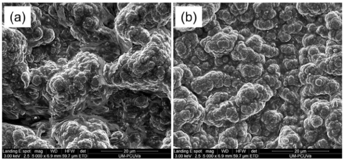
The structure of the PPy films prepared by CP was observed by scanning electron microscopy, confirming the typical granular raspberry shape for all the samples. The structures of the films deposited onto PM and wrought SS are similar. PPy films had a globular structure at different sizes. Fig. 3 shows how the pores were fully covered by the PPy film, though the roughness of the surface was replicated somehow. Homogeneous and compact distributed PPy covered the entire surface of the samples.
Fig. 3. Scanning electron microscope images of PPy film on (a) WSS-PPy and (b) NWC-PPy.
3.2.1. Open circuit potential
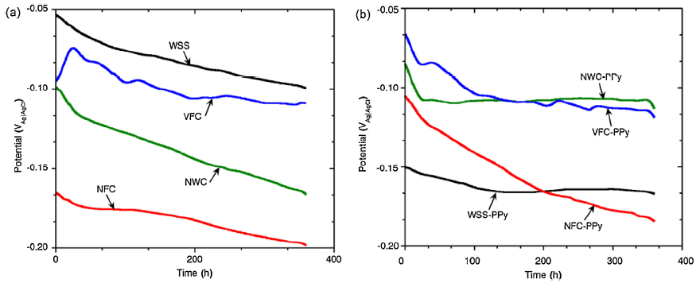
Fig. 4 shows the OCP evolution for every sample in the PBS solution. From the results collected in Fig. 4(a), it becomes clear that porosity has a negative effect. The three PM samples showed a lower potential than the wrought SS. However, not only porosity is relevant; the microstructure is different for every PM sample and this is reflected in different OCP curves. The lower potential was registered for the sample sintered in nitrogen and furnace cooled; this is a consequence of an unstable passive film due to the chromium depletion matrix on the lamellar constituent. Furthermore, a clear potential stabilization was not reached, the potential decreased gradually with increasing time, indicating the continuous dissolution of the metal. In this sense, it seems that the PPy coating stabilizes the OCP. In effect, when the samples are coated, as can be seen in Fig. 4(b), the potential evolution tends to a horizontal line.
Fig. 4. OCP evolution of the (a) uncoated and (b) coated samples in PBS solution.
The coated samples showed a more stable potential that could be explained due to the effect of anodic protection of PPy that helped the formation of a stable layer. Moreover, some additional relevant points can be outlined. First, the OCP curves were different for every sample, even though they all had a similar deposit of PPy film. Consequently, the microstructure of the material has an influence and, since the PPy film is in between the corrosive media and the metallic material, it must be assumed that diffusion is allowed and the anodic protection effect is more important than the simple barrier effect. Second, NFC-PPy is not clearly stabilized. Accordingly, its microstructure must be the dominant factor. In fact, it is the most heterogeneous sample. It is mainly formed by austenite and the lamellar constituent. The other two samples were free of this lamellar constituent. This component causes chromium depletion, which promotes the instability of the passive films. Finally, the PPy coating is not exerting a positive effect on wrought SS. The OCP is nobler for uncoated WSS. This is perhaps due to a lack of adherence. This does not happen for PM materials since the pores act as fixation points. Furthermore, the coatings might have some defects and this will enable the formation of galvanic interactions. Qi et al. [[56],[57]] have proven that PPy film suffers continuous cathodic polarization and the substrate suffers anodic polarization. When the substrate is not inert or not well passivated, as is the case of 13Cr SS in NaCl, the corrosion of the substrate could be accelerated [57]. It is interesting to note that WSS-PPy and VFC-PPy exhibited a clear potential shift at the end of the test with respect to the uncoated samples. This and the existence of a stable OCP indicated that these samples showed enhanced corrosion resistance compared to the uncoated ones.
3.2.2. Anodic polarization measurements
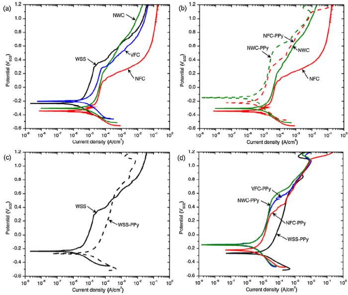
Fig. 5(a) shows the potentiodynamic polarization curves of uncoated materials in a PBS solution for the different sintering conditions, as well as for the wrought material. Because of porosity, the real current density cannot be correctly estimated. It is not possible to calculate such a real current density because the wet area inside the pores remains undetermined, so the current density is overestimated [48]. For sintered materials, on a comparative basis, since its porosity is around 11%-13%, the influence of porosity will always be similar.
Fig. 5. Potentiodynamic polarization curves, in PBS solution, of (a) uncoated samples, (b) coated and uncoated NWC and NFC, (c) coated and uncoated WSS, and (d) all coated samples.
All curves in Fig. 5(a) had a similar shape, stainless steel in the PBS solution undergoes localized corrosion characterized by a rapid increase of the anodic current at breakthrough potential, where the damage to the passive film occurs and pitting/crevice corrosion is initiated. The cathodic polarization branch shifted to a lower potential for samples sintered in nitrogen. The anodic polarization branch, which corresponds to the metal dissolution and passive layer formation, became more stable for WSS. The passive potential range was wider and the current density lower for NWC and VFC samples than for NFC, which showed the lowest breakdown potential. These facts can be understood due to the differences in the microstructures. First, the chromium distribution of NFC is heterogeneous due to the presence of the lamellar constituent and precipitates. Second, the nitrogen is completely dissolved in the NWC, which correspondingly enhances corrosion resistance. In addition, VFC and WSS show an austenite phase free of precipitates. Finally, WSS is a sample free of pores and with a real exposed area lower than that of the others and therefore the curve shifted to the left.
The PPy coating modifies all the polarization curves, but in a very different way for porous and non-porous materials. For PM samples sintered in nitrogen, a remarkable change was observed (Fig. 5(b)). The corrosion potential shifted to nobler values and the anodic polarization branch became more stable. Coated samples have a good passivation performance with a lower stable passive current density and a higher breakdown potential. Furthermore, NWC-PPy showed better corrosion behavior than NFC-PPy. Though not as good as that of NWC and NFC, the sample sintered in a vacuum, VFC, showed a similar behavior.
The corrosion protection of a metal by conducting polymer is assumed to be induced by an oxidative property and a barrier effect of the polymer layer covering the metal. The oxidative property of the polymers cause a positive potential shift to the passive state. The protective role of PPy can be explained [18] by the fact that, when this polymer is in a conductive state, the electroactive interface could be displaced from its usual metal/solution location to a polymer/solution interface. This could explain the corrosion potential changes observed in coated samples. The anodic protection provided by coating explained the more stable passive layer and the decrease in passive current density.
However, the effect of the PPy coating on the wrought sample was the opposite (Fig. 5(c)). In this case, no beneficial effect was evident. On the contrary, its current density was higher and its corrosion potential was lower. This is in good correlation with the OCP test results. This phenomenon has also been reported in other studies of electroactive polymer films for SS [[19],[44]]. The polarization current for the coated SS includes the contribution from the corrosion of bare substrate and possibly from the oxidation of PPy film. A further increase of current density was also observed.
Accordingly, it can be concluded that coated PM samples have better anodic corrosion behavior than wrought sample (Fig. 5(d)). It can be said that PPy exerts a beneficial effect only on porous materials. The high adherence obtained due to the presence of pores may be one of the reasons for this improvement.
The effect of the PPy coating on the corrosion resistance of SS was examined by Tafel analysis. Table 3 shows these Tafel parameters for all the samples submitted to polarization in PBS. Again, the effect of the PPy coating is different for sintered and wrought samples. For PPy coated PM samples, a nobler potential and lower current density than the uncoated material was obtained. For WSS, the coated sample had a lower potential and higher current density than the corresponding uncoated sample. The highest values of corrosion potentials were observed for NWC-PPy and VFC-PPy. Accordingly, the lowest values of current densities were also found. Therefore, these results were in accordance with the previous paragraphs. The more homogeneous microstructures observed for NWC and VFC explain their better behavior as compared with NFC. For the NFC sample, the PPy is not able to passivate the chromium depletion area of the lamellar constituent through a galvanic interaction, thus justifying the worse corrosion behavior of the material, even if the coating is present.
Table 3 Corrosion potential and corrosion current density calculated by Tafel analysis of samples in PBS solution.
| Sample | Corrosion potential (VSCE) | Corrosion current density (10-3 A/m2) |
|---|---|---|
| NFC | -0.346 | 11.48 |
| NFC-PPy | -0.225 | 8.43 |
| NWC | -0.307 | 6.74 |
| NWC-PPy | -0.150 | 3.84 |
| VFC | -0.200 | 4.45 |
| VFC-PPy | -0.147 | 2.32 |
| WSS | -0.238 | 4.17 |
| WSS-PPy | -0.268 | 9.54 |
3.2.3. EIS measurements
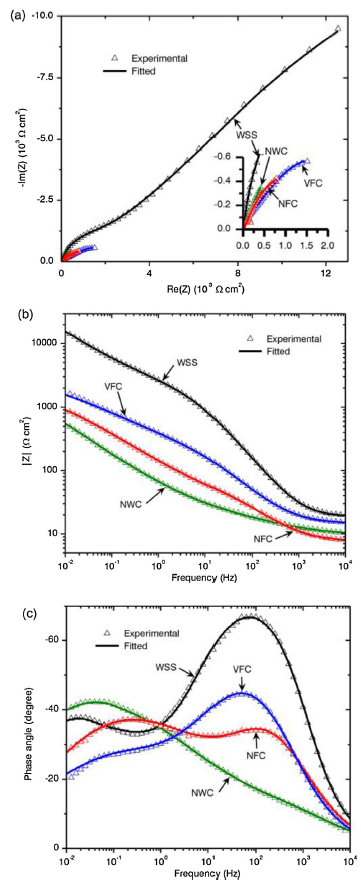
The electrochemical impedance spectra in the form of Nyquist and Bode plots for the uncoated samples in the PBS solution at open circuit potential are shown in Fig. 6. Two regions of different response can be easily observed (Fig. 6(a)). At a high frequency, a partial depressed semicircle was obtained, from which the charge transfer resistance (Rct) could be graphically obtained. At a lower frequency, the response in some cases was considered as the Warburg impedance because a typical straight line representing the diffusion process was seen [17]. This is in accordance with the EIS results obtained on conventional stainless steel substrates [58].
Fig. 6. Electrochemical impedance spectra in the form of (a) Nyquist and (b) and (c) Bode plots of the uncoated samples in PBS solution. Results of the fitting to the equivalent electric circuit are included.
The EIS curves of WSS are different from those of uncoated PM samples. For the former, the Rct obtained from the observable part of the semicircle was larger than those obtained for PM samples (Fig. 6(a)). This increase in the Rct value is attributed to the absence of porosity, as well as a more stable passive film, so a better corrosion behavior is implied. For SS samples, these plots show a mechanism kinetically controlled by electron transfer between the metal and the corrosive environment at the bottom of the oxide film. The higher exposed area explains their worse behavior for porous samples.
In the Bode plot, log|Z| - logf, several resistive parts were observed (Fig. 6(b)). One at the high frequency range, describing the resistance of the solution, Rs, which was much lower than that of the electron transfer resistance, Rct, depicted at a low frequency. This latter is clearly the highest for WSS, indicating that the passive film formed due to oxidation is more corrosion protective than those formed on PM samples. The frequency dependence of the phase angle (Fig. 6(c)) showed the additional elements, i.e., the double layer and oxide capacitances.
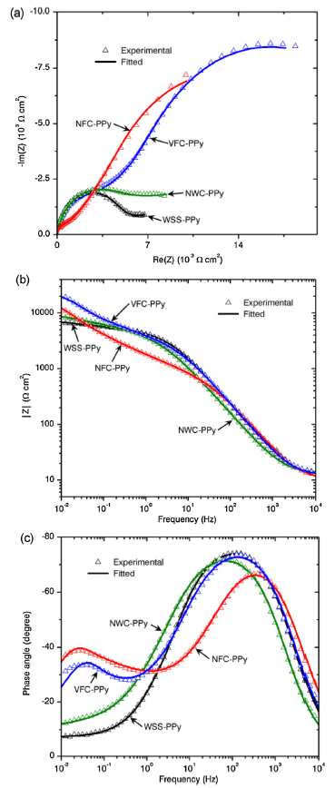
The large differences between wrought and PM samples disappeared after covering the samples with the PPy film (Fig. 7). Only NFC-PPy showed lower Rct and, additionally, a long diffusion tail was observed, showing that the charge transfer process was faster than the diffusion process. Thus, the diffusion is the step that controlled the corrosion rate of this sample because the electronic transfer is very fast.
Fig. 7. Electrochemical impedance spectra in the form of (a) Nyquist and (b) and (c) Bode plots of coated samples in PBS solution. Results of the fitting to an equivalent electric circuit are included.
For the interpretation of the impedance spectra, an appropriate equivalent electric circuit should be chosen. Fig. 8 shows the equivalent electric circuit proposed, after some trials with typical electric circuits, to interpret the EIS spectra of the uncoated and coated samples. Fig. 6, Fig. 7 also collect the results of the fitting.
Fig. 8. Equivalent electric circuit to interpret EIS measurements.
The parameters of the fitting are presented in Table 4, Table 5. Chi-square values, χ2, were used to evaluate the quality of the fittings. χ2 values were of a magnitude to the order of 10-4. In the proposed model, Rs corresponds to the resistance of the electrolyte, R1 and C1 correspond to the resistance and CPE (constant-phase element) of the passive film, Rcorr and C2 are assigned to the polarization resistance and CPE of the double layer, and Ws corresponds to the Warburg element. This equivalent electric circuit has usually been used to interpret the corrosion mechanism of passive materials [[59],[60]]. Two semicircles were not observed in the Nyquist plots, so the sum of R1 + Rcorr is defined as the electric charge-transfer resistance, i.e., Rct, and this is related to the corrosion resistance of the samples.
Table 4 EIS equivalent circuit parameters of uncoated samples.
| Sample | Rs (Ω cm2) | C1-C (10-4 sn Ω-1 cm-2) | C1-n | R1 (Ω cm2) | C2-C (10-4 sn Ω-1 cm-2) | C2-n | Rcorr (Ω cm2) | Ws-Rw (Ω cm2) | Ws-s (s) | Ws-n | χ2 (10-4) |
|---|---|---|---|---|---|---|---|---|---|---|---|
| WSS | 18.6 | 0.26 | 0.80 | 1848 | 1.80 | 0.45 | 4.7 | 90882 | 46.5 | 0.4 | 1.9 |
| NWC | 9.5 | 1.80 | 0.54 | 13.4 | 48.0 | 0.49 | 155 | 3664 | 14 | 0.5 | 0.8 |
| NFC | 7.4 | 4.10 | 0.69 | 48.1 | 29.8 | 0.50 | 180 | 1877 | 0.01 | 0.5 | 1.4 |
| VFC | 14.3 | 2.25 | 0.71 | 260 | 15.53 | 0.44 | 169 | 2939 | 0.03 | 0.5 | 1.5 |
Table 5 EIS equivalent circuit parameters of coated samples.
| Sample | Rs (Ω/cm2) | C1-C (μF/cm2) | C1-n | R1 (Ω/cm2) | Cdl-C (μF/cm2) | Cdl-n | Rcorr (Ω/cm2) | Ws-R (Ω/cm2) | Ws-S (s) | Ws-n | χ2 (10-5) |
|---|---|---|---|---|---|---|---|---|---|---|---|
| WSS-PPy | 12.3 | 13 | 0.9 | 3412 | 380 | 0.21 | 855 | 12156 | 0.4 | 0.6 | 4.0 |
| NWC-PPy | 13.2 | 23 | 0.86 | 2781 | 230 | 0.27 | 1494 | 15681 | 0.5 | 0.5 | 4.1 |
| NFC-PPy | 9.8 | 14 | 0.9 | 718 | 150 | 0.6 | 1614 | 22267 | 0.34 | 0.5 | 5.2 |
| VFC-PPy | 11.9 | 1.5 | 0.9 | 3161 | 200 | 0.5 | 2060 | 53087 | 0.02 | 0.5 | 8.4 |
CPE representing a shift from the ideal capacitor behavior was used instead of the typical capacitor; the depressed circle is an indication of this. The impedance of a CPE is defined as:
$Z_{CPE}=\frac{1}{C(jw)^{n}}$ (1)
where j is the imaginary unit; when n = 1, the CPE describe an ideal capacitor, when n = 0 it is an ideal resistor, and when n = -1 it is a pure inductance, while C is a constant. In this case, the lack of homogeneities at the microscopic level in the meta-electrolyte interface (such as surface roughness, adsorbed species or other distributed properties) indicated that C is not a real capacitance and its units are sn Ω-1 cm-2 instead of F cm-2.
Finally, Ws is the generalized finite Warburg element that accounts for the diffusion of the mobile charge, which can be expressed as:
$W_{s}=R_{W}\frac{tanh([jws]^{n})}{(jws)^{n}}$ (2)
where Rw represents the diffusion resistance and s = λ2/D, where λ is the effective diffusion thickness and D is the effective diffusion coefficient of the involved species. A finite-length Warburg behavior indicates that corrosive species can diffuse toward the substrate [61].
The process involved here is characterized by two time constants, namely the high-frequency time constant (C1-R1) and low-frequency time constant (C2-Rcorr). The first time constant is represented by the capacitance of the passive film in pore-free areas and R1 can be related to the ionic resistance of the pore area of the passive layer. This would be the film oxide resistance. The defects on the passive layer may be a pathway to the penetration of the electrolyte. The existence of these pores promotes the appearance of this second electrical constant, which may indicate that the steel is submitted to a rapid corrosion due to the formation of a non-protective layer. The physical meaning of the second time constant is the response of the substrate on the passive layer defect zones impregnated with electrolyte. C2 and Rcorr can be related to the double-layer capacitance and the charge-transfer resistance through the porous layer, respectively.
Resistance at very high frequencies corresponds to the Rs, which, according to Table 4, remains almost constant in all uncoated samples. Table 4 also shows the passive resistance, R1 value, which strongly depends on the existence of pores or defects into which the electrolyte can penetrate. The value of R1 for WSS is significantly higher than the resistances of the PM samples. This could be related to a more stable passive film for wrought samples. Nevertheless, the value of C1-n for this case is the highest (0.9) and indicates a low amount of defects. Rcorr values are significantly greater than the values associated with the passive resistance, R1, for PM samples, indicating that the protection provided was predominantly due to the barrier layer. As commented above, the sum of R1 and Rcorr is defined as the polarization resistance (electric charge-transfer resistance, Rct) and is related to the corrosion resistance; this clearly decreases for porous samples. The Warburg impedance could be used for the comparison of wrought and sintered samples due to their permeability. The lower Ws-Rw value obtained for sintered samples indicates that they have a more permeable structure and the diffusion of corrosive species is easier than for WSS.
Table 5 shows the EIS results of the PPy-coated samples. The equivalent electric circuit used to interpret EIS spectra of coated samples was the same as that used for uncoated samples, i.e., passive films having a two-layer structure [60]. Nevertheless, in this case, R1 and C1 correspond to the sum of the resistance and capacitance of the outer coating layer and the inner passive layer, instead of only the passive film described for uncoated samples. The defects on the coating layer may be a pathway to the penetration of the electrolyte. The existence of these defects promotes the appearance of this second electrical constant, which is the response of the steel on the layer with defects impregnated with electrolyte. C2 is, and Rcorr can be, related to the double-layer capacitance and the charge-transfer resistance through the defective layer, respectively.
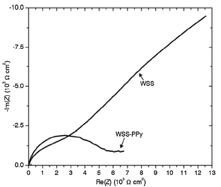
The effect of the PPy coating on WSS is shown in Fig. 9. The diameter of the semicircle, Rct, for the PPy coated sample was found to be greater than that for the uncoated specimen; this is attributed to some protective effect of this coating. As can be seen in Fig. 10, the protective effect of this coating was also observed for PM samples, i.e., the diameter value of the high frequency semicircle, Rct, strongly increased with the coating. For PM samples, the changes are much more evident than that for WSS. The impedance is clearly higher for coated PM samples at any frequency. Therefore, the PPy coating is especially effective for PM samples.
Fig. 9. Electrochemical impedance spectra in the form of Nyquist plot of WSS and WSS-PPy in PBS solution.
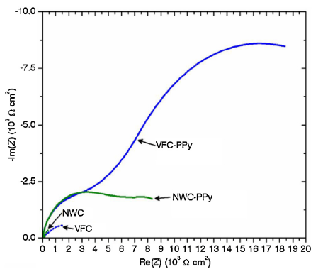
Fig. 10. Electrochemical impedance spectra in the form of Nyquist plot of uncoated and coated NWC and VFC in PBS solution.
The EIS results of PPy-coated samples exhibited an increase in total impedance and a decrease in the capacitance as compared to uncoated samples. These results indicate that the PPy-coating acts as an effective barrier between the substrate and the environment to increase the corrosion resistance. The C1-n values are very close to 1 for all of them. Conducting polymer coatings provide anodic protection to iron-based materials [61]. The self-passivation of material improves due to the galvanic interaction between the coating and the base material, so it is possible to passivate a defective pore area with protective oxide film. An important increase in the resistance of the coating was observed as a consequence of the reduction of the polymer due to the galvanic coupling referred to above. The C2-n values in the interface with the substrate are lower, and similar values are reported by Gonzalez et al. [43] on a bilayered polypyrrole 316 L SS coating.
It was found that both R1 and Rcorr were higher for the coated sample than for the corresponding uncoated sample. This suggests that the PPy coating is a more effective barrier than the spontaneous passive film. These differences were more significant for samples with pores.
Among the coated samples, the wrought SS showed the lowest Rcorr, since the electrolyte up-taking process occurred more rapidly through the coating of the wrought sample because of the lower adherence of the film. Therefore, this confirmed that the adhesion of PPy on the metal substrate is better for porous steel. On the other hand, a strong increase in the Warburg impedance was observed when coated and uncoated samples are compred. It was apparent from Table 5 that Ws-Rw values of coated PM samples were higher than those of the WSS-PPy. This indicates that the coating for these former samples has a less permeable structure and the diffusion of corrosive species is more difficult.
The coverage of the metallic surface is one of the most important rules for preventing corrosion. In this sense, the coverage of PPy for PM samples is more effective than that for wrought SS. Therefore, the electrodeposition of PPy layers for corrosion prevention is especially recommended for porous SS. For a possible medical application, biocompatibility and a longer degradation study should be also carried out, but they are not the issues of this work. The effect of the longer immersion time in the PBS medium on the corrosion performance of the samples is a matter of practical interest that will be investigated in a future work. Also, the incorporation of TiO2 particles in PPy coating will be studied taking account the synergetic combination of nanoparticles and conductive polymers for other applications [62].
On the other hand, the ion transport through the passive PPy bilayer is related to protective properties. We can assume that the dopant is retained in the film due to its large size, and then the polymer film exhibits cation exchange properties; it has also been reported that DBSA is able to form micelles to give a negative charge and repels anions [31]. All of them justify the success of the PPy coating on porous SS.
Therefore, the corrosion protection mechanisms on porous SS can be explained by the following facts: there are no large defects in the coating, the penetration of ions is hindered due to the DBSA counterion, which is relatively fixed in the film and, when the transport through the coating occurs, the PPy acts as an efficient oxidizer to maintain the steel in the passive state. Furthermore, since the pores also become passivated, the highest corrosion resistance was found for the sample sintered in nitrogen and water-cooled. The chromium precipitation observed for the furnace-cooled sample justifies a low content of chromium present in the passive film, therefore promoting a worse behavior. It is suggested that the microstructure has a significant role in the passivation of SS promoted by conductive polymers.
Powder metallurgy materials, because of their intrinsic porosity, do not show good corrosion behavior. It is therefore advisable to look for possible solutions to this matter. PPy doped with DBS has been successfully deposited on porous SS samples with different chemical and microstructural characteristics, a homogeneous and adherent film has been observed in all cases. The efficacy of PPy coating very much depends on how and where it is applied and on the conditions of the corrosion experiment.
The electrochemical behavior of coated and uncoated porous and wrought materials were investigated in PBS. The OCP evolution results showed that porosity in uncoated porous samples is negative in terms of corrosion resistance. However, PPy coating stabilizes the OCP, which is different for every porous sample as a function of the microstructure. PPy film promotes modifications of the electrochemical behavior of the samples. Finally, the PPy coating does not exert such a positive effect on wrought SS due to adherence problems that may lead to an OCP decrease.
The PPy coating modifies all the polarization curves and porous samples have better anodic corrosion behavior than wrought sample, so the pores play a beneficial role in the adherence of the coating.
The electrochemical impedance spectra of coated and uncoated materials in PBS solution have also been studied. Fitting it to a typical equivalent electric circuit helped to identify the mechanisms involved. The results are consistent with those obtained with previous techniques. Impedance spectra showed that the corrosion mechanism changes for porous SS due to the application of a PPy coating, which may act as an efficient oxidizer to maintain the steel in the passive state even in the pores that are typically zones of difficult passivation.
These results suggest that the PPy coating improves the corrosion resistance of porous 316 L. The best protection results are found for austenitic powder metallurgy stainless steel sintered in nitrogen, water-cooled and coated with a conducting PPy film, which is interpreted by the more stable passive film generated by anodic protection. It is a promising material for bio implants. The biocompatibility studies in vitro will be the object of future research.
This work was financially supported by the MINECO-FEDER (No. AGL2015-67482-R) and the Junta de Castilla y Leon and FEDER (No. VA275P18). Celia Garcia-Hernandez would also like to thank Junta de Castilla y León for a grant (BOCYL-D-4112015-9).

 WeChat
/
| 〈 |
|
〉 |
