Search for articles:
Meng-Jie Chang , Kang Wang
Corresponding authors:
Received: 2019-04-13
Revised: 2019-06-17
Accepted: 2019-06-26
Online: 2020-01-01
Copyright: 2020 Editorial board of Journal of Materials Science & Technology Copyright reserved, Editorial board of Journal of Materials Science & Technology
More
Abstract
TiO2/Bi4Ti3O12 hybrids have been widely prepared as promising photocatalysts for decomposing organic contaminations. However, the insufficient visible light absorption and low charge separation efficiency lead to their poor photocatalytic activity. Herein, a robust methodology to construct novel TiO2/Bi4Ti3O12/MoS2 core/shell structures as visible light photocatalysts is presented. Homogeneous bismuth oxyiodide (BiOI) nanoplates were immobilized on electrospun TiO2 nanofiber surface by successive ionic layer adsorption and reaction (SILAR) method. TiO2/Bi4Ti3O12 core/shell nanofibers were conveniently prepared by partial conversion of TiO2 to high crystallized Bi4Ti3O12 shells through a solid-state reaction with BiOI nanoplates, which is accompanied with certain transition of TiO2 from anatase to rutile phase. Afterwards, MoS2 nanosheets with several layers thick were uniform decorated on the TiO2/Bi4Ti3O12 fiber surface resulting in TiO2/Bi4Ti3O12/MoS2 structures. Significant enhancement of visible light absorption and photo-generated charge separation of TiO2/Bi4Ti3O12 were achieved by introduction of MoS2. As a result, the optimized TiO2/Bi4Ti3O12/MoS2-2 presents 60% improvement for photodegrading RhB after 120 min irradiation under visible light and 3 times higher of apparent reaction rate constant in compared with the TiO2/Bi4Ti3O12. This synthetic method can also be used to establish other photocatalysts simply at low cost, therefore, is suitable for practical applications.
Keywords:
Photocatalytic degradation of pollutants is attracting enormous attentions as one of the most promising approach for solving environmental pollutions [[1], [2], [3], [4], [5]]. Among the various semiconductor photocatalysts, titanium dioxide (TiO2) is the most investigated photocatalyst for its low cost, high chemical resistance and non-toxicity. However, the wide band gap of TiO2 (3.2 eV) restricts its practical use due to the low response to visible light and insufficient solar conversion efficiency. In addition, high recombination probability of photo-generated charges is not favorable to generate useful active species for decomposing organic pollutes. In order to achieve higher photocatalytic efficiency, TiO2 was usually coupled with another smaller band gap semiconductor to form heterojunction. This is because of not only the good visible light absorption, but also the excellent charge separation at the two material interfaces in the heterojunction. As such, a large number of narrow band gap semiconductors have been conjugated with TiO2 for the purpose of high photocatalytic activity in the past decades.
Bismuth titanate is a kind of narrow band gap semiconductor with several crystal phases, such as refractive sillenite phase Bi12TiO20, dielectric pyrochlore phase Bi2Ti2O7 and ferroelectric perovskite phase Bi4Ti3O12. Among them, Bi4Ti3O12 (BTO) has received tremendous attentions in the photocatalytic application field due to its special layered structures [6,7]. Up to now, researchers have achieved significant progress on the synthesis and photocatalytic use base on TiO2/BTO nanocomposites in a variety of microstructures [8,9]. For example, Bi4Ti3O12 nanosheets modified electrospun TiO2 nanofibers and TiO2 nanotube arrays were prepared for the visible light photocatalysis, respectively [10,11]. Zhao et al. reported Bi2O3/Bi4Ti3O12/TiO2 double-heterostructured from TiO2 nanobelts as high-performance photocatalysts [12]. Furthermore, Bi4Ti3O12/TiO2 heterostructures on carbon nanofiber support and Bi2Ti2O7/TiO2 composite nanowire arrays on glass substrate were acquired for convenient photocatalytic application [13,14]. These Bi4Ti3O12/TiO2 heterostructures were generally synthesized by a hydrothermal or solvothermal reaction of presynthesized TiO2 nanomaterials in a Bi contained solution with more or less enhancement of photocatalytic performance compared to the sole TiO2. However, the Bi4Ti3O12/TiO2 composites still suffer from several drawbacks to meet the future photocatalytic application. On one hand, the Bi4Ti3O12 cannot response to the visible light in a wide wavelength range for its relative large band gap ($\widetilde{2}$.7 eV). On the other hand, long reaction time and serious reaction conditions such as strong basic solution are required for preparing the BTO via hydrothermal method. Therefore, it is of critical importance to develop novel Bi4Ti3O12/TiO2 photocatalysts with strong absorption in a wide light range, simple preparation procedure and high visible light photocatalytic activity.
More recently, the two dimensional MoS2 nanomaterials have been widely studied in the field of photocatalysis owe to the advantages of unique structural, electronic and optical properties [15]. Particularly, integrating MoS2 with other semiconductors can strongly extend the light absorption to the visible light region, enhance the surface area and improve the charge transfer between semiconductor interfaces for higher photocatalytic performance. Consequently, MoS2 has been combined with a large number of other semiconductors such as C3N4 [16], TiO2 [17,18], CdS [19], CoFe2O4 [20], ZnO [21], Cu2S [22] and to boost the photocatalytic activity. These composites can be synthesized by hydrothermal wrapping of MoS2 on semiconductoral surface or growth of semiconductors on MoS2 nanostructures. Such achievements have demonstrated the immense potential of 2D MoS2 in the photocatalytic field.
Herein, we report a novel synthesis of TiO2/BTO/MoS2 core/shell heterostructures for enhanced photocatalytic degradation of RhB dyes. In comparison with the previous work, the TiO2/BTO/MoS2 composites obtained in this work are featured with the following structural and composition aspects. First, electrospun TiO2 nanofibers were chosen for the convenience of low aggregation, large surface area and easy collection. Second, BTO shells were deposited on the TiO2 nanofiber surface (TiO2/BTO) by simple SILAR process and solid-state reaction, which process are advantage of easy operation, green synthesis and low cost [23,24]. Third, immobilization of MoS2 nanosheets on the TiO2/BTO fiber surface provides the high specific surface area and wide visible light absorption, which has rarely been studied before. Furthermore, the core/shell structures ensure the largest contact between different components, as well as high charge separation efficiency at the semiconductor interface for excellent visible light photocatalytic performance.
Polyvinylpyrrolidone (PVP, molecular weight Mw = 1,300,000), tetrabutyl titanate (TBT) and ammonium molybdate tetrahydrate ((NH4)6Mo7O24·4H2O) were purchased from Aladdin Inc. Thiocarbamide (CH4N2S), potassium iodide (KI), bismuth nitrate pentahydrate (Bi(NO3)3·5H2O) and organic solvents were obtained from Guoyao Chemical Co., China. All regents were used as received without further purification. The deionized water (DI water) was produced by Ulupure machine.
In a typical process, 0.8 g PVP powder was added into a mixed solution comprising of 4.5 mL of ethanol, 2.5 mL of acetic acid and 1 mL of TBT, which was then continuously stirred at least 6 h to form a transparent solution with slight yellow color. The electrospinning process was carried out at room temperature (26 °C) at humid of 40%. In brief, the polymer solution was loaded into a syringe and extruded out at a feeding rate of 5 μL min-1. The nanofibers were collected on a negatively charged electrode under a high voltage of 10 kV. The distance between the positively stainless steel needle and the negatively foil was set as 15 cm. The as-spun nanofibers were calcined in air at 500 °C with a heating rate of 5 °C min-1 to obtain the TiO2 nanofibers.
TiO2/Bi4Ti3O12 (TiO2/BTO) core/shell nanofibers were prepared by two steps: BiOI decoration on TiO2 nanofiber surface by successive ionic layer adsorption and reaction (SILAR) method and subsequent solid-phase reaction at high temperature. For one cycle SILAR process, Bi(NO3)3 (5 mM), DI water, KI (5 mM) and DI water solutions were alternatively poured into a TiO2 nanofiber contained beaker. Bi(NO3)3 (or KI) was left to stand for 2 min in the TiO2 nanofiber contained beaker every time to ensure enough adsorption and reaction of the ions on the fiber surface, and then the TiO2 nanofibers were washed with DI water for twice. In this work, 30 SILAR cycles were applied to grow BiOI nanoplates on the TiO2 nanofiber surface (TiO2/BiOI). After dried at 60 °C, the TiO2/BiOI nanofibers were sintered at 600 °C for 2 h with a heating rate of 5 °C min-1 to produce the TiO2/BTO core/shell nanofibers.
TiO2/BTO/MoS2 core/shell nanofibers were constructed by hydrothermal growth of MoS2 nanosheets on the TiO2/BTO fiber surface. To be specific, (NH4)6Mo7O24·4H2O and CH4N2S with weight ratio of 1:2 were dissolved in 30 mL DI water to prepare the hydrothermal growth solution, in which 30 mg of as-prepared TiO2/BTO nanofibers were added and shaken for 2 min. Then the mixed solution was decanted into a 50 mL Teflon-lined stainless steel autoclave and heated to 180 °C for 10 h in an electrical oven. When cooling down to room temperature, the TiO2/BTO/MoS2 fibers with black colour were separated from the reaction solution through natural sedimentation and washed with DI water for several times. The products obtained at added (NH4)6Mo7O24·4H2O of 30, 50 and 125 mg in the hydrothermal solution were labeled as TiO2/BTO/MoS2-1, TiO2/BTO/MoS2-2 and TiO2/BTO/MoS2-3, respectively.
Scanning electron microscopy (SEM) images were captured with a Hitachi S4800. Transmission electron microscopy (TEM) and high resolution transmission electron microscopy (HRTEM) were carried out using a Tecnai-G2-F30 microscope at an accelerating voltage of 300 kV. X-ray diffraction (XRD) measurements were measured on a Shimadzu D6000 X-Ray diffractometer with CuKα radiation at a scan rate of 0.02° per step. The ultraviolet-visible diffuse reflectance (UV-vis DR) spectra were recorded using a Shimadzu UV-2600 spectrometer by using BaSO4 as a reference. The room-temperature photoluminescence (PL) spectra were investigated utilizing the RF-6000 with an excitation wavelength of 295 nm. X-ray photoelectron spectroscopy (XPS) was conducted with a PHI-5702 X-ray photoelectron spectrometer. The photocurrents were measured with an electrochemical workstation (CHI 660E, Chenhua, Shanghai) in a standard three electrode system with the fiber sample as the working electrode, a Pt foil as the counter electrode, and Ag/AgCl (saturated KCl) as the reference electrode. The working electrodes were prepared by casting ethanol slurry containing around 0.2 mg of fiber samples on active area of 1 cm2 fluorine doped tin oxide (FTO) glass. A 0.1 M Na2SO4 aqueous solution was used as electrolyte.
The photocatalytic activities of the fibrous samples were evaluated by decomposing RhB aqueous solution under visible light irradiation from a Xe lamp (PLS-SEX300UV) with a 400 nm UV cut-off filter. In the test process, 10 mg of catalyst was added into 10 mL of Rhodamine B (RhB) (10 mg L-1) aqueous. The solution was first put in dark for 30 min to achieve adsorption-desorption equilibrium and then illuminated under the Xe lamp for photocatatical degradation of RhB. The UV-vis absorption of the RhB solution was recorded by a T6 UV-vis spectrophotometer every 20 min.
Fig. 1 exhibits the procedure for fabricating TiO2/BTO/MoS2 composite nanofibers, including sequential production of TiO2 nanofibers, decoration of BiOI nanoplates, solid-state synthesis of TiO2/BTO and coating of MoS2 nanosheets. Anatase TiO2 nanofibers were gained by using electrospinning and subsequent calcination at 500 °C. Then BiOI nanoplates were readily anchored on the TiO2 fiber surface by SILAR process. The formed TiO2/BiOI nanofibers were treated by solid-state reaction at 600 °C, which resulted in the synthesis of BTO and concurrent loss of BiOI. TiO2 nanofibers serve as template and reactant for the preparation of TiO2/BTO nanofibers during the solid-state reaction. Finally, MoS2 nanosheets were attached on the TiO2/BTO fiber surface through hydrothermal method.
Fig. 1. Scheme for fabricating TiO2/BTO/MoS2 hybrid nanostructures: electrospinning and calcination to form TiO2 nanofibers (a, b); TiO2/BiOI preparation by SILAR method (c); TiO2/BTO formation by high temperature solid-state reaction (d); MoS2 decoration by hydrothermal method (e).
Fig. 2 presents the XRD patterns of TiO2, TiO2/BTO and TiO2/BTO/MoS2 nanofibers, respectively. As shown in Fig. 2(a), the diffraction peaks centered at 25.26°, 48.02°, 54.02°and 62.51° are indexed to the (101), (200), (105) and (204) planes of anatase TiO2 phase, respectively [8]. In the meantime, no other peaks are observed in Fig. 2(a), meaning that TiO2 nanofibers with pure anatase phase were formed at calcinations temperature of 500 °C. After SILAR immobilization of BiOI nanoplates and subsequent thermal treatment at 600 °C for 1 h, the resulted TiO2/BTO fibrous sample presents a series of sharp diffraction peaks at 16.22°, 21.66°, 23.30°, 30.06°, 32.90°, 36.91°, 38.40°, 39.84°, 47.34°, 51.48°, 56.98° and 69.47, which can be assigned to the (060), (080), (111), (171), (200), (062), (0 14 0), (082), (202), (0 14 2), (371) and (3 15 1) planes, respectively, of the rhombohedral phase of BTO (JCPDS 35-0795) [25]. Thus the BTO is successfully prepared through the solid-state reaction at high temperature. The existence of diffraction peak of anatase TiO2 in Fig. 2(b) suggests that only part of TiO2 namofibers were converted to BTO. Apart from the peaks of BTO and anatase TiO2 in Fig. 2(b), another new diffraction peak can be clearly noted at 27.45°, which can be ascribed to the (110) diffraction plane of rutile TiO2 phase. This new appeared peak of rutile TiO2 can be explained by the certain transformation of TiO2 from anatase to rutile phase during the high temperature calciantion process, which has been demonstrated by others that the more rutile TiO2 were produced as increasing the calcination temperature [26]. Additionally, no diffraction peaks of BiOI exist in Fig. 2(b) confirms that BiOI disappeared after the high temperature solid-state reaction. The curve for TiO2/BTO/MoS2-2 nanofibers in Fig. 2(c) shows nearly the same diffraction peaks as that of TiO2/BTO in Fig. 2(b), implying that the structure of the TiO2/BTO was not changed during the hydrothermal reaction. Moreover, no observation of diffraction peaks of MoS2 proves that the synthesized MoS2 by hydrothermal method is just a fewer layers in thickness with fairly weak diffraction peak. The XRD results demonstrate that high crystallized BTO was readily synthesized by the solid-state reaction accompanied with the partial transformation of TiO2 from anatase to rutile phase.
Fig. 2. XRD patterns of TiO2 nanofibers calcined at 500 °C (a), TiO2/BTO nanofibers obtained at 600 °C (b) and TiO2/BTO/MoS2-2 nanofibers (c); standard XRD patterns of anatase TiO2 (d) and rutile TiO2 (e).
SEM measurement was carried out to monitor the morphology and microstructure evolution of the nanofibers. The as-calcined TiO2 fibers in Fig. 3(a) has relatively smooth surface with average diameter of 250 nm. As shown in Fig. 3(b) of the TiO2/BiOI nanofibers, lamellae shaped BiOI nanoplates with uniform size of several hundred nanometers in diameter and 17 nm in thickness are grown perpendicularly to the TiO2 fiber surface [27]. The whole TiO2 fiber surface is fully covered by BiOI nanoplates, meaning the decoration of large amounts of BiOI nanoplates through 30 cycle SILAR growth. Fig. 3(c) depicts the SEM image of TiO2/BTO by calcination of TiO2/BiOI nanofibers in Fig. 3(b) at 600 °C for 1 h. Instead of the lamellae shaped BiOI nanoplates and smooth TiO2 nanofibers, the TiO2/BTO fiber surface becomes quite coarse attached with some nanopartiecles. This microstructure change is caused by the composition conversion from BiOI to BTO. As we know, it is necessary of the contact between different reactants for the solid-state reaction. So only the outside surface of the TiO2 fiber template can be converted to BTO, which has been verified by the XRD characterization in Fig. 2(b). Therefore, the fibrous morphology of TiO2/BTO is well retained like that of TiO2 during the high temperature treatment. The SEM images of TiO2/BTO/MoS2 with different quantity MoS2 modification are shown in Fig. 3(d)-(f). For the TiO2/BTO/MoS2-1 sample, trace MoS2 nanosheets were synthesized and most of the TiO2/BTO nanofibers are naked (Fig. 3(d)) without modification of MoS2. As increasing the precursor concentration of MoS2, the TiO2/BTO fiber surfaces are uniformly decorated with crumpled MoS2 nanosheets, as well as the gradually incensement of the fiber diameter due to the generation of thick MoS2 nanosheet shells (Fig. 3(e) and (f)). The SEM results in Fig. 3 suggest that TiO2/BTO composite nanofibers can be successfully prepared by the solid-state reaction. Controllable quantities of MoS2 nanosheets could be coated on the TiO2/BTO fiber surface by the convenient hydrothermal growth method.
Fig. 3. SEM images of TiO2 nanofibers calcined at 500 °C (a), TiO2/BiOI nanofibers after 30 cycle SILAR process (b), TiO2/BTO nanofibers treated at 600 °C (c), TiO2/BTO/MoS2-1 (d), TiO2/BTO/MoS2-2 (e) and TiO2/BTO/MoS2-3 nanofibers (f).
Energy dispersive spectroscopy (EDS) of TiO2/BTO/MoS2-2 fibers was carried out to detect the sample composition. The fiber samples were sonicated in DI water for 30 s, and then 50 μL of solution was dropped on a piece of Si wafer and dried for the EDS measurement. As shown in Fig. 4(a), all the peaks of Bi, Ti, O, Mo and S elements can be found in the EDS spectra. The intense peak of Si is originated from the Si substrate for sample loading. Moreover, the EDS elemental mapping of two nanofibers was performed to further examine the elemental composition shown in Fig. 4(c)-(g). It can be noted that all the Bi, Ti, O, Mo and S are uniformly distributed on the whole fiber. Specifically, the uniform distribution of Bi in Fig. 4(c) suggests that BTO shells were coated on the whole fiber surface through the solid-state reaction between TiO2 and BiOI at high temperature. Meanwhile, from the Mo and S mapping results (Fig. 4(f) and (g)), it is clear that MoS2 nanosheets are homogeneously deposited on the TiO2/BTO fiber surface during the hydrothermal growth to fabricate three layered TiO2/BTO/MoS2 core/shell nanofibers.
Fig. 4. EDS pattern (a) and elemental mapping (b-g) of the TiO2/BTO/MoS2-2 fiber.
The microstructure and morphology of the nanofibers were deep characterized by TEM measurements. As shown in Fig. 5(a), the TiO2 fiber surface is smooth. A clear spacing of 0.33 nm in the HRTEM image in Fig. 5(b) is assigned to the (110) lattice plane of anatase TiO2 [28]. By using the SILAR growth of BiOI and high temperature solid-state reaction, some protuberance occurs on the fiber surface (Fig. 5(c)). The HRTEM image of the fiber outside edge shown in Fig. 5(d) exhibits the crystal face with a space of 0.30 nm, corresponding to the characteristic lattice (171) plane of BTO materials. The morphology change and HRTEM micrograph of the fiber surface confirms the success in synthesizing BTO shells through the solid-state reaction. Actually, because of the necessary contact of different components, BTO should be formed only on the fiber surface. The shells with light colour outside the fiber surface is observed in the TEM image for TiO2/BTO/MoS2-2 nanofibers (Fig. 5(e)), revealing that MoS2 nanosheets have been deposited on the whole TiO2/BTO fiber surface. Furthermore, the (002) crystal planes of MoS2 with lattice fringe width of 0.61 nm indicates only several layer MoS2 were stacked along the c axis, which is in accordance with the XRD results in Fig. 2. The SEM and TEM results prove that a three layered core/shell TiO2/BTO/MoS2 nanofibers have been successfully constructed by subsequent SILAR process, solid-state reaction and hydrothermal techniques.
Fig. 5. TEM and HRTEM images of TiO2 nanofibers calcined at 500 °C (a, b), TiO2/BTO nanofibers treated at 600 °C (c, d) and TiO2/BTO/MoS2-2 nanofibers (e, f).
As well-known, UV-vis spectroscopy has been proven to be an effective optical characterization method to understand the electronic structure of semiconductors. The UV-vis diffuse reflectance (DR) spectroscopy was acquired to evaluate the light absorption properties of the TiO2/BTO and TiO2/BTO/MoS2 nanofibers. As displayed in Fig. 6(a), the TiO2/BTO sample presents absorption in the wavelength region shorter than 440 nm [29]. After modification with MoS2, the TiO2/BTO/MoS2-1 (Fig. 6(b)) and TiO2/BTO/MoS2-2 (Fig. 6(c)) nanofibers exhibit evident enhanced light absorption in the range 400-800 nm, which can be attributed to the strong visible light absorption of MoS2 for its narrower band gap. When too much MoS2 was modified on TiO2/BTO fiber surface, the TiO2/BTO/MoS2-3 (Fig. 6(d)) sample absorbed nearly all the visible light. The change of the light absorption property was also accompanied by a color variation from light yellow of the TiO2/BTO to deep brown of the TiO2/BTO/MoS2-1 and TiO2/BTO/MoS2-2 nanofibers but complete black color of TiO2/BTO/MoS2-3. Due to the excellent visible light absorption property, the TiO2/BTO/MoS2 should be suitable for photocatalytic decomposition of organic contaminants under visible light irradiation.
Fig. 6. UV-vis diffusion reflectance spectra of TiO2/BTO (a) TiO2/BTO/MoS2-1 (b), TiO2/BTO/MoS2-2 (c) and TiO2/BTO/MoS2-3 composite nanofibers (d).
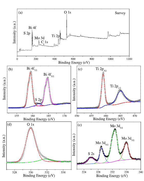
To investigate the chemical position of the prepared composite, the TiO2/BTO/MoS2-2 composite was further analysed by XPS measurement. The elements of Bi, Ti, O, Mo and S are all contained in the full scan XPS spectrum in Fig. 7(a). Fig. 7(b)-(e) illustrate the high-resolution XPS spectra of Bi 4f, Ti 2p, O 1s, Mo 3d and S 2p. The two peaks at binding energy centered at 160.2 eV and 165.8 eV in Fig. 7(b) are assigned to Bi 4f7/2 and Bi 4f5/2 of Bi3+, respectively. The peak located between Bi 4f5/2 and Bi 4f7/2 at 161.3 eV corresponds to S 2p. Two bands at 458.9 eV and 464.6 eV with a typical spin-orbit doublet of 5.7 eV are attributed to Ti 2p3/2 and Ti 2p1/2, respectively, indicating the normal Ti4+ in composite materials (Fig. 7(c)) [30]. With respect to the XPS spectra of O 1s in Fig. 7(d), the peaks at 530.1 eV should be attributed to the lattice oxygen O2- of Bi-O and Ti-O band in BTO and TiO2. The peaks at 531.9 eV might be assigned to the surface adsorbed oxygen specie. The observed two main peaks at 228.4 eV and 231.7 eV of Mo 3d in Fig. 7(e) are attributed to the doublet Mo 3d5/2 and Mo 3d3/2 of Mo4+, respectively. Meanwhile, a peak at binding energy of 235.3 eV reveals the presence of Mo6+ in the composites [31]. Additionally, the peak at 225.4 eV can be indexed to S 2 s. Consequently, the XPS results confirm the fabrication of TiO2/BTO/MoS2 composites.
Fig. 7. XPS patterns of TiO2/BTO/MoS2-2: overall XPS (a), high resolution spectrum of Bi 4f (b), Ti 2p (c), O 1s (d) and Mo 3d and S 2s (e).
The photocatalytic activity was examined by decomposition of RhB aqueous under visible light irradiation. The degradation efficiency was presented as C/Co, wherein Co and C are the absorption of RhB at the wavelength 554 nm for the starting solution and the solution irradiated after each interval, respectively. Fig. 8(a) and (b) displays the typical absorption spectra changes of RhB as increasing the irradiation time in the presence of TiO2/BTO and TiO2/BTO/MoS2-2 nanofibers, respectively. It is noted that TiO2/BTO/MoS2-2 sample shows significant enhanced degradation ability in comparison with the TiO2/BTO nanofiber. More importantly, no evident shift of the maximum absorption peak is observed with prolonging the irradiation time, suggesting that the organic RhB molecules were oxidized other than the photocatalytic decolouration. Fig. 8(c) exhibits the visible light photocatalytic activities of TiO2/BTO, pure MoS2 powders synthesized by hydrothermal method and TiO2/BTO/MoS2 samples. As can be seen, 32%, 51%, 58%, 87% and 79% of RhB are decomposed by TiO2/BTO, MoS2, TiO2/BTO/MoS2-1, TiO2/BTO/MoS2-2 and TiO2/BTO/MoS2-3 after 120 min irradiation, respectively. All the TiO2/BTO/MoS2 samples exhibit higher photocatalytic ability than either TiO2/BTO or MoS2 samples. Among the TiO2/BTO/MoS2 samples, TiO2/BTO/MoS2-1 presents the lowest photocatalytic activity because of trace decoration of MoS2 nanosheets on the TiO2/BTO nanofiber surface. While increasing the proportion of deposited MoS2 nanosheets, the photocatalytic ability of TiO2/BTO/MoS2-2 is improved apparently probably due to the effective visible light absorbance and charge transfer at the semiconductor interface. However, too much introduction of MoS2 result in full coverage of thick MoS2 on the TiO2/BTO surface, which might cause low charge transfer separation efficiency on the semiconductoral interface as well as decrease of photocatalytic performance in TiO2/BTO/MoS2-3 sample. That is a proper amount of MoS2 modification is required to achieve effective improvement of visible light photocatalysis. [32]
Fig. 8. UV-vis spectral changes of RhB degraded by the TiO2/BTO (a) and TiO2/BTO/MoS2-2 (b) nanofibers; photodegradation efficiency of RhB in the presence of different catalysts under visible light irradiation (c); RhB curves of ln(Co/C) versus irradiation time for different catalysts (d).
To better elucidate the photocatalytic ability over different catalysts, the reaction kinetics of the photocatalysis were calculated by the first order kinetics model equation:
ln(Co/C) = kt (1)
where Co and C are the concentrations of RhB solution when the irradiation time is zero and t, respectively. As can be seen from the apparent reaction rate constants (k) calculated via the first order linearfit data in Fig. 8(d), the apparent reaction rate constant of TiO2/BTO/MoS2-2 is nearly 6 times higher than that of TiO2/BTO nanofibers, verifying that the introduction of MoS2 nanosheets significantly boosts the photocatalytic activity. These results are accordance with the photocatalytic degradation results in Fig. 8(c). The improved photocatalytic activity of the TiO2/BTO/MoS2 compared to untreated TiO2/BTO fibers can be attributed to the enhanced visible light absorption of visible light, charge transfer as well as specific surface areas.
The photocatalytic stability and reusability of TiO2/BTO/MoS2-2 were evaluated by repeated degradating RhB solution. After each photocatalysis reaction, the TiO2/BTO/MoS2-2 fiber samples were collected and washed with DI water for several times, and then dried for next cycle. Fig. 9 shows the results of RhB degradation by TiO2/BTO/MoS2-2 fibers for 3 cycle degradation with 30 min adsorption in dark and 120 min illumination in each cycle. Even certain decrease of the photocatalytic activity was observed as increasing the recycle times, degradation of RhB is still maintained at 56% after 3 recycling runs, indicating relative stability of the photocatalyst. These results suggest that the TiO2/BTO/MoS2 fibers are suitable for reuse in the visible light photocatalytic application.
Fig. 9. Repeated photocatalytic degradation of RhB over TiO2/BTO/MoS2-2 fibers.
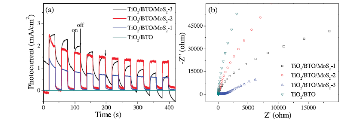
To study the increased separation efficiency of photoinduced charge by introduction of MoS2 nanosheets, transient photocurrents of TiO2/BTO and TiO2/BTO/MoS2 were measured as shown in Fig. 10(a). It is found that fast photocurrent responses through on-off cycles are detected in these photocatalysts under light irradiation. Moreover, all the TiO2/BTO/MoS2 samples are more photoactive with larger photocurrent than that of untreated TiO2/BTO sample. The remarkble enhancement on the photocurrent density demonstrates higher separation efficiency of photogenerated charge carriers in TiO2/BTO/MoS2 composite. Particularly, TiO2/BTO/MoS2-2 has the largest photocurrent, which is agreement with its highest photocatalytic performance shown in Fig. 8(c).
Fig. 10. Transient photocurrent responses (a) and EIS Nyquist plots (b) of electrodes of TiO2/BTO, TiO2/BTO/MoS2-1, TiO2/BTO/MoS2-2 and TiO2/BTO/MoS2-3 composite nanofibers.
Fig. 9(b) shows the Nyquist plots of the EIS spectra for TiO2/BTO and TiO2/BTO/MoS2 electrodes under light irradiation, which present typical semicircle. The diameter of the semicircle is related to the charge-transfer resistance at the electrode/electrolyte interface. Clearly, the Nyquist plot of TiO2/BTO has the largest semicircle diameter than that of TiO2/BTO/MoS2, which means that the TiO2/BTO/MoS2 composite possesses a relatively smaller charge-transfer resistance under light irradiation. These results in Fig. 10 suggest that an increased separation efficiency of photogenerated electron-hole pairs and fast interface charge transfer occurs in the TiO2/BTO/MoS2 composite.
The photoluminescence (PL) spectra of the TiO2/BTO, TiO2/BTO/MoS2-1, TiO2/BTO/MoS2-2 and TiO2/BTO/MoS2-3 composite nanofibers were tested to further characterize the charge separation and transfer efficiency. As shown in Fig. 11, all the TiO2/BTO/MoS2 composite nanofibers display lower fluorescence emission intensity at peak of 400 nm than that of TiO2/BTO nanofibers. The fluorescence quenching of the TiO2/BTO/MoS2 composite nanofibers indicates that higer transfer and lower recombination efficiency of charge carrier took place in the TiO2/BTO/MoS2 fiber samples, which is helpful to enhance the photocatalytic performance of TiO2/BTO/MoS2 photocatalyst.
Fig. 11. Photoluminescence spectra of TiO2/BTO, TiO2/BTO/MoS2-1, TiO2/BTO/MoS2-2 and TiO2/BTO/MoS2-3 composite nanofibers.
In summary, novel TiO2/Bi4Ti3O12/MoS2 fibrous structures were successfully established by involving subsequent production of electrospun TiO2 nanofibers, deposition of BiOI nanoplates on TiO2 fiber surface by SILAR method, generation of TiO2/Bi4Ti3O12 via solid-state reaction and hydrothermal decoration of MoS2 nanosheets. The TiO2 nanofibers were partial converted to high crystallized Bi4Ti3O12 shells during the solid-state reaction with BiOI nanoplates, accompanied with certain transition from anatase to rutile phase. Thanks to the strong visible light absorption and large surface area of MoS2, as well as the quick charge transfer at the semiconductor interface, the TiO2/Bi4Ti3O12/MoS2 exhibits apparently improved response to visible light and photo-induced charge separation. Importantly, all the TiO2/Bi4Ti3O12/MoS2 samples have overall enhanced visible light photocatalytic performance against to degrade RhB solution. The present work not only introduces a highly active photocatalyst but also provides a feasible strategy for construction of a low-cost ternary Bi based heterojunction structure under mild conditions.
This work was supported financially by the National Natural Science Foundation of China (Nos. 21501140, 21403165, 51372197), the Outstanding Youth Science Fund of Xi'an University of Science and Technology (No. 2019YQ2-06) and the Key Innovation Team of Shaanxi Province (No. 2014KCT-04).

 WeChat
/
| 〈 |
|
〉 |


