Search for articles:
Hongyu Wu , Yunping Li, Kechao Zhou
Corresponding authors:
Received: 2019-02-11
Revised: 2019-04-9
Accepted: 2019-06-24
Online: 2020-01-01
Copyright: 2020 Editorial board of Journal of Materials Science & Technology Copyright reserved, Editorial board of Journal of Materials Science & Technology
More
Abstract
In this study, the selective laser melting (SLM) technology has been employed to manufacture a nickel-based superalloy which was conventionally prepared through powder metallurgy (PM) route. The microstructural features and defects were systematically investigated both prior to and after heat treatment and compared with the PM counterpart. Both solidification cracking and liquation cracking were observed in the SLM specimen in which the grain misorientation and low melting point (γ + γ’) eutectic played a vital role in their formation mechanism. Columnar grains oriented along building direction were ubiquitous, corresponding to strong <001> fiber texture. Solidification cell structures and melt pools are pervasive and no γ’ precipitates were detected at about 10 nm scale before heat treatment. After super-solvus solution and two-step aging treatments, high volume fraction γ’ precipitates emerged and their sizes and morphologies were comparable to those in PM alloy. <001> texture is relieved and columnar grains tend to become more equiaxed due to static recrystallization process and grain boundary migration events. Significant annealing twins formed in SLM alloy and are clarified as a consequence of recrystallization. Our results provide fundamental understandings for the SLM PM nickel-based superalloy both before and after heat treatment and demonstrate the potential to fabricate this group of alloys using SLM technology.
Keywords:
Nickel-based superalloys are widely used for fabricating hot-section turbine components of aircraft engine due to their exceptional tensile strength, creep resistance and fatigue crack growth resistance at elevated temperature [[1], [2], [3]]. These excellent mechanical performances result from the synergistic strengthening effects such as γ’ precipitation strengthening, solid solution hardening as well as the grain boundary strengthening [[4], [5], [6], [7]]. To improve the fuel efficiency, highly-alloyed nickel-based superalloys have been designed to elevate turbine inlet temperature, leading to great challenges in manufacturing because these alloys are more prone to segregation or thermal cracking when casting in large size [8]. Thus, powder metallurgy approach was applied to process these alloys due to its advantage in improving macro-segregation. However, this manufacturing process is quite complicated and costly. In general, PM nickel-based superalloys are typically processed through a sequence of master alloy melting, atomization, hot compaction, hot extrusion, isothermal forging and heat treatment [1,9]. Wherein, the microstructure, namely, the γ grains [10,11] and γ’ precipitates [12,13], should be elaborately controlled to balance the strength, creep and fatigue properties.
Recently, the additive manufacturing (AM) technique has drawn significant attention due to its ability to direct fabricate geometrically complex component with high efficiency [14,15]. In this context, several important structural/metallic materials, including stainless steels [16], aluminum alloys [17,18], titanium alloys [19], cobalt alloys [20] as well as nickel-based superalloys [21,22] have been processed through this technique. The related microstructure features, defect formation mechanism, mechanical performance and associated strengthening mechanism have also been extensively investigated.
For the nickel-based superalloys, the current researches primarily focused on the Inconel-series alloys [[23], [24], [25]] and cast nickel-based alloys [26,27]. Extensively investigations have shown that the manufacturing parameters and laser scan strategy have a strong effect on the microstructures of AM fabricated nickel alloys. For instance, increasing laser energy density makes part be more dense [28,29] and leads to fine and uniformly columnar dendrites from coarsened columnar dendrites [28]. Weak texture and a mixture of fine and coarsen grains can be achieved under lower laser power while strong <001> texture and columnar grains are associated with higher laser power [30]. Besides, the laser scan strategy also has a significant impact on the texture of AM manufactured parts [31,32]. As a result, the occurrence of texture leads to the anisotropy in mechanical property [29,33]. In addition to the typical columnar dendrites and grains, the cell structures are pervasive on the transverse plane whose boundaries are decorated with high density of dislocations [34,35].
Due to the particularity of AM techniques, there may be some defects in AM prepared parts. As a result of large thermal gradient during the manufacturing process, large amount of residual stress is introduced [36] leading to the formation of micro-crack in the part. The occurrence of crack will harm the mechanical strength of the materials doubtlessly [37]. Consequently, the optimization of processing parameter or post processing treatment is necessary to eliminate this kind of defect and improve the mechanical property of the AM superalloys. Previous studies [24,38] have demonstrated that the crack-free AM nickel superalloys exhibit superior tensile strength than the wrought or cast counterparts, which should be attributed to the refined grain [34] and additional strengthening effect, namely, the cell structure (dislocation) strengthening [39].
However, it remains little known what will happen using AM techniques to process PM nickel-based superalloys. Investigation [40,41] related to this issue has rarely been reported. Yang et al. [40] established the correlation between processing parameters and cracking tendency and classified three types of cracks in direct laser fabrication (DLF) Rene 104. While for the laser solid forming (LSF) Rene 88DT, the authors mainly attributed cracks to the liquation cracking [41]. Both of the above works [40,41] emphasize that cracking is inevitable in AM PM superalloys and can be improved effectively through hot-isostatic pressing. Although providing some deeper insights into the cracking formation, these works remain fundamental issues to be clarified, e.g., the influence of grain misorientation on cracking.
Motivated by that, on one hand, AM techniques deliver a promising approach to building PM superalloys parts without complicated process and materials removal (low cost and high efficiency). On the other hand, detailed investigation on the microstructural evolution is still absence for AM PM alloys. An attempt was made in the current work using SLM (one of the AM techniques) technology to manufacture a nickel-based superalloy which should be prepared through PM process. The microstructural features, defects and associated formation mechanisms were investigated in detail both before and after heat treatment using multiple techniques, i.e., electron microscopy and electron backscattered techniques as well as thermodynamic calculation. Additionally, its microstructure and hardness were compared with the PM counterpart. This study deepens the fundamental understanding of SLM PM nickel-based superalloys and should be helpful to facilitate the ongoing researches on this issue.
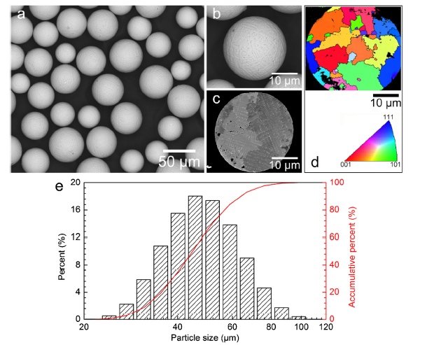
Table 1 shows the nominal composition and the composition of raw powders (determined using the inductively couple plasma-atomic emission spectrometry (ICP-AES) technology) of the investigated alloy. The prealloyed powders were prepared by plasma rotating electrode process (PREP) and then sieved with 100 mesh size. The particle size distribution measured using a laser granulometry (Malvern Micro-Plus) is depicted in Fig. 1(e) and its average size is 50.7 μm. The SEM micrographs show that all powders exhibit spherical morphology (Fig. 1(a) and (b)) and consisted of micrometer-sized dendrites with random orientation (Fig. 1(c) and (d)).
Table 1 The nominal and experimentally measured (powders) chemical composition of the investigated nickel-based superalloy (wt%).
| Ni | Co | Cr | Mo | W | Al | Ti | Ta | C | B | Zr | Hf | |
|---|---|---|---|---|---|---|---|---|---|---|---|---|
| Nominal | Bal. | 13.0 | 12.0 | 4.0 | 4.0 | 3.0 | 4.0 | 4.0 | 0.05 | 0.025 | 0.05 | 0.2 |
| Powders | Bal. | 13.03 | 11.78 | 4.02 | 3.95 | 3.06 | 3.95 | 3.80 | 0.051 | 0.024 | 0.048 | 0.2 |
Fig. 1. BSE images showing (a) the spherical morphology and (b) surface of the prealloyed powders, (c) cross section of micrometer-sized dendrites with random orientations (d) and (e) particle size distribution measured by using a laser granulometry and the average size is calculated to be 50.7 μm.
SLM additive manufacturing was performed under the Farsoon 271 M SLM system using the following processing parameters based on the previous work in our group [29], a laser power (P) of 300 W, laser scanning velocity (v) of 1000 mm/s, hatch space (h) of 0.1 mm and layer thickness (t) of 0.03 mm. The corresponding laser energy density is calculated by the following equation [29]:
$E=\frac{P}{vht}$ (1)
By calculation, it is 100 J/mm3. A meander scanning strategy (raster with 67° rotation for each layer) was used for all trials as it has been optimized to minimize residual stress [42], see Fig. S1 in Supplementary information. Cylindrical specimen with diameter of 10 mm and height of 10 mm were manufactured for subsequent investigation.
For the PM alloy, the powder was loaded in the stainless steel container for degassing and then sealed when the pressure was less than 10-3 Pa followed by hot extrusion performed on a 1000 t extruder at 1100 °C using an extrusion ratio of 16:1.
The SLM and PM specimens were imposed by super-solvus solution heat treatment at 1180 °C for 1 h (the solvus of γ’ phase for this alloy is 1150 °C calculated using Pandat software with Ni database) followed by air cooling, and then a two-step aging treatment was applied at 650 °C for 24 h and 760 °C for 16 h followed by air cooing, respectively.
For microscopic observation, all specimens were ground and polished down to 0.03 μm colloidal silica finish. The SLM specimens were etched to observe the grain structure using the etchant of 10 ml 30% H2O2, 20 ml HCl and 20 ml water [24] and a field emission gun scanning electron microscope (Quanta 650 FEG-SEM, FEI) was served for microscopic observation along the XZ and XY planes with an acceleration voltage of 15 kV. Electron backscatter diffraction (EBSD) measurements were performed in the FEG-SEM with step sizes of 0.2 (for alloy powders) or 1 μm (for both SLM and PM specimens) and an acceleration voltage of 20 kV, the data were collected through the Channel 5 software. To observe the nanometer-sized γ’ precipitates, the specimens were etched using a solution of 33 ml H2O, 33 ml CH3COOH, 33 ml HNO3 and 1 ml HF upon the secondary electron mode. Statistical analysis about γ’ precipitates was performed using software ImageJ. In each case, three SEM images were measured and the average value and corresponding standard error were reported.
Vickers hardness tests were carried out using the Buehler Micrometer 5100 hardness tester with the load of 9.8 N and the dwell time of 15 s. To guarantee the precision, each specimen was tested 10 times and the corresponding average value was reported.
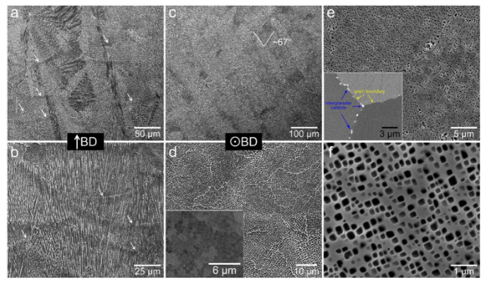
Fig. 2 shows the representative microstructures on XZ and XY planes in SLM alloy as well as in PM alloy. From Fig. 2(a) and (b), the layered melt pools can be observed along the building direction. Their boundaries, as marked by the white arrows, denote the interface of the solidified materials and remolten materials induced by laser. It is the most striking characteristic in SLM or other AM manufactured nickel-based alloys [38,43] and its shape and geometry are strongly related to the laser beam profile [44], laser scanning strategy [32] and processing parameters [44].
Fig. 2. BSE images showing (a) the melt pools and (b) columnar dendrites on the XZ plane. In both images (a, b), the melt pool boundaries were indicated by white arrows. BSE images revealing (c) the laser scanning traces with a rotation angle of 67° and (d) honeycomb-like domains (cell structure) on the XY plane. The insert in (d) is a high magnification BSE image. (e) SEM image exhibiting the inter- and intragranular precipitates in PM alloy. The insert image in (e) is a BSE image showing the carbides located on the grain boundaries. (f) High magnification image for intragranular γ’ phase.
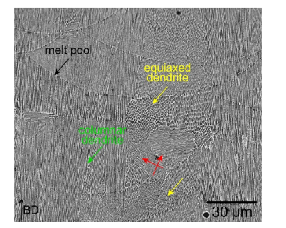
Meanwhile, columnar dendrites grow epitaxially in the successive solidification layers along the building direction as a result of the heat flow conducts primarily via the substrate of previously solidified layers [24]. This phenomenon is akin to that in directional solidification technology in which columnar or single crystal can be obtained upon the one-dimension cooling path [45]. In addition, the melt pool boundary can strongly influence the growth of dendrite due to its important role in heat flow conduction [46]. Fig. 3 reveals the existence of some dendrites which grow along the normal direction of melt pool boundaries (red arrows). Furthermore, equiaxed dendrites are also observed (indicated by yellow arrow) under the interaction of multiple melt pool boundaries. These observations suggest the heat conduction mechanism through melt pool boundary at the micron scale.
Fig. 3. BSE image revealing the influence of melt pool boundaries on the growth of dendrites.
Fig. 2(c) and (d) clearly reveals the microstructural features on the XY plane, wherein the angle between two neighbor traces is nearly 67° which is consistent with the rotation angle of laser during deposition. A closer examination discloses that the microstructure is composed of honeycomb-like cell structures, which is further verified by the backscatter electron micrograph (Fig. 2(d) and the inset). The honeycomb-like structure, decorated with high density of dislocations [16,43], is pervasive in the additive manufacturing metal alloys and has been confirmed as a strengthening factor through dislocation hardening effect [39].
Noteworthy, no γ’ precipitates are detected in the SLM alloy up to 10 nm scale, in accordance with the result reported in Ref. [42]. In general, considerable amount of γ’ phase would generate during cooling following the thermo-mechanical process [47], e.g. hot extrusion or isothermal forging. The absence of γ’ precipitates in the present case should be largely ascribed to the fast cooling rate (103-108 K/s) in SLM [14]. In this context, the movement of solute atoms are heavily limited and far from the critical condition to trigger precipitation [42] although the high undercooling is achieved during the fast cooling process [48,49].
In contrast, the PM alloy consists of equiaxed grains with an average grain size of 15 μm by means of EBSD measurement (Fig. 4(c)) and intergranular precipitates such as the primary γ’ phases (whose size locates in the range from 500 to 1000 nm), carbides (enriching with Ta, Ti and C elements, marked by blue arrows, Fig. S2 can be clearly distinguished on the grain boundaries (Fig. 2(e) and the inset) [1,2]. Inside the grain (Fig. 2(f)), cuboidal γ’ precipitates are observed and their average size is measured to be 194 ± 0.7 nm. Based on the image analysis, the total area volume fraction is 30.6%±0.7% for the intragranular γ’ and 3.3%±0.8% for the intergranular γ’, in which the volume fraction of intergranular γ’ was obtained using the total volume fraction of γ’ (measured from lower magnification SEM images containing both inter- and intragranular γ’) subtracts the volume fraction of intragranular γ’ (form higher magnification SEM images including only intragranular γ’).
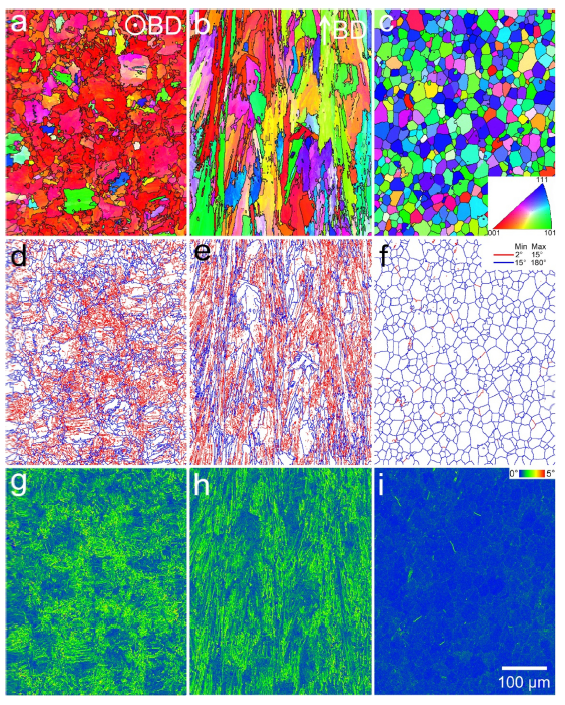
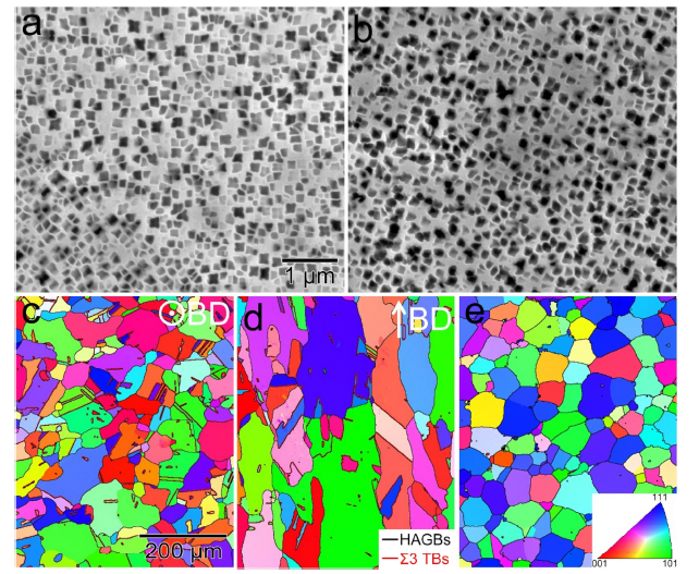
Fig. 4. EBSD IPF maps (a-c), grain boundary maps (d-f) and KAM maps (g-i) for the SLM and PM alloys. (a, d, g) are observed from the XY plane while (b, e, h) are from XZ plane of the SLM alloy. (c, f, i) Corresponding images of the PM alloy.
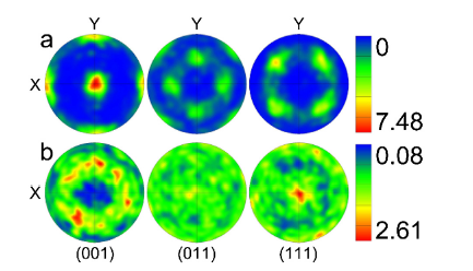
To further understand the formation mechanism of columnar grains, inverse pole figure (IPF) maps are utilized to unveil the grain orientation information on both XY and XZ planes. In the view of XY plane, the grains are roughly equiaxed (Fig. 4(a)) and the dominated orientations of columnar grains are parallel with <001> direction [37] (thus strong <001> fiber texture can be observed, see Fig. 5(a)) which is also reported in SLM prepared Inconel 738LC [23] and Inconel 718 [29]. On the XZ plane, the columnar grains are evident and their orientations are more random than that in XY plane (Fig. 4(b)). Under the current laser scanning strategy (the scanning direction rotates by 67° every layer), the center of melt pools in the neighboring layers presents an angle of 67°. In this case, the heat flow conduction along the normal direction of melt pool boundary in the overlapped melt pools will not be conserved except the direction parallel to building direction [32]. Thus, the heat flow direction or temperature gradient direction is primary along the building direction during the deposition process, then the growth along this direction is naturally preferred. As a consequence, the columnar grain morphology and preferred orientation (<001> fiber texture) are accordingly generated. In contrast, the grains are equiaxed with more random orientations and behave as the weak texture (Fig. 5(b)) after hot extrusion and the average grain size is smaller ($\widetilde{1}$5 μm) than that in the SLM alloy. Based on the microscopic observation, it is straightforward that the grain boundaries of PM alloy are faceted relative to those of SLM alloy. It is necessary to measure the misorientation distribution and give a quantitative analysis under these two different processes. Corresponding grain boundary maps show that the SLM alloy has a higher percentage of low-angle grain boundaries (LAGBs, 2°-15°) comparing with the PM alloy (Fig. 4(d)-(f)) [16]. The kernel average misorientation (KAM) maps (Fig. 4(g)-(i)), calculated up to the first neighbor shell with a maximum misorientation angle of 5°, are also provided. Higher KAM values are clear detected in SLM specimen than that in PM one. Since the KAM map relates to the accommodated strain in a specimen [50] which demonstrates that the high lever of stored strain remains in the SLM alloy.
Fig. 5. Pole figures for (a) SLM alloy and (b) PM alloy. Note that the pole figure corresponding to SLM alloy is obtained from the XY plane.
Four types of defects have been observed in the SLM alloy, i.e., solidification crack, liquation crack, bonding defect and pore. Their characteristics and formation mechanisms will be presented in the following sections.
Previous researches have been reported that enlarged amount of Al and Ti (the critical value for these two elements is 6 wt%) will lead to high sensitivity to cracking in nickel-based superalloys [40,41]. However, these two elements, as γ’-forming solute atoms, are added with a high content (7.0 wt% of Al + Ti) to maximize the precipitation strengthening effect in the investigated alloy. Consequently, the inevitable cracking, both of solidification and liquation cracking, should be partially attributed to the enhanced content of Al and Ti which acts as an intrinsic factor making the alloy be high sensitivity to cracking during manufacturing process.
3.2.1. Solidification cracking
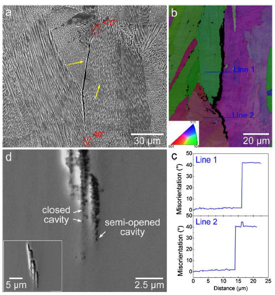
The prevalent solidification cracking and liquation cracking in AM manufactured nickel-based alloys [40,46] and other metallic materials, have been observed in SLM specimen, as revealed in Fig. 6, Fig. 7. From Fig. 6(a), a typical solidification crack originates from the site where the crystallographic misorientation increases between adjacent dendrites, which reaches $\widetilde{4}$0° (red circle at the bottom of Fig. 6(a)), much higher than the critical grain boundary misorientation of $\widetilde{1}$3° for crack formation [51] and then propagates along the path with high misorientation (high angle grain boundary, HAGB) [44,46]. It is further supported by the EBSD observation in Fig. 6(b) (overlapped image of band contrast and IPF maps). Fig. 6(c) presents the quantitative measurement of corresponding misorientation relative to the first point as a function of distance of line 1 and line 2 in Fig. 6(b), where significant misorientation emerges across the crack. Similar results have also been reported in selective electron beam melting (S-EBM) manufactured Inconel 718 alloy [52] and SLM manufactured Inconel 738LC alloy [44]. Interestingly, some cases of crack healing are observed when the misorientation is close to or less than 0°, in accordance with Fig. 6(d) (inset) and (a), respectively. These findings highlight the important role of misorientation on causing and healing the solidification cracking in SLM specimen. It is known generally that at the last stage, the secondary arms of primary dendrites bridge each other to complete the solidification process [52]. Where the misorientation can strongly influence the coalescence behavior via tuning the grain boundary energy, γgb [51,53]. This phenomenon could be qualitatively rationalized based on the critical coalescence undercooling, ΔTc, which is calculated from the following equation:
ΔTc=$\frac{(γ_{ gb }-2γ_{sl})}{ΔSfδ}$ (2)
where γsl is the solid-liquid interface energy, ΔSf is the entropy of fusion per unit volume and δ is the thickness of the diffuse interface ($\widetilde{1}$ nm) [52]. In the low misorientation case (corresponding to the low-angle grain boundary, LAGB), or referred as “attractive” case [53], γgb is smaller than 2γsl, thus liquid between dendrites is unstable and bridging occurs leading to crack-free solidification at the last stage. However, increasing misorientation makes the γgb exceed 2γsl (as a result, ΔTc> 0, the “repulsive” case [53]). Thus, the liquid between dendrites remains stable at a lower temperature enhancing the possibility of cracking. Further examination shows that the solidification cracking initiates from both closed and semi-opened shrinkage cavities, as shown in Fig. 6(d). This phenomenon is consistent with the previous wisdom [54] that strain concentration is preferentially accommodated at the cavity [55] leading to the crack development.
Fig. 6. (a) BSE image showing a solidification crack, (b) overlapped image with IPF and band contrast maps, (c) relative to the first point misorientation marked as line 1 and line 2 and (d) solidification cracks originate from closed or semi-opened shrinkage cavities, the insert showing the occurrence of crack healing.
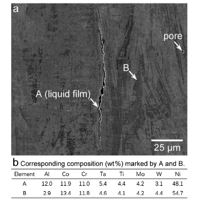
Fig. 7. (a) BSE image showing a typical liquation crack and (b) composition corresponding to liquid film within the clack and γ matrix, respectively.
The investigations in Refs. [44,52] show the segregation of B and/or Zr along the grain boundaries resulting in a deleterious effect on the solidification susceptibility in nickel-based superalloys. These low melting elements with the ability to lower the solidus point promote the formation of crack through wetting the solid dendrites [52]. Considering that the used alloy in this work contains a small amount of B and Zr, it is excepted that they are also one of the causes for the observed cracks.
3.2.2. Liquation cracking
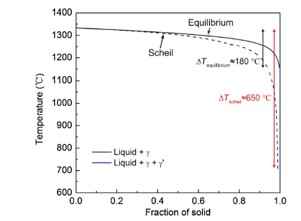
Fig. 7(a) shows the BSE image of a liquation crack in the SLM alloy. An obvious light-colored film within the crack is detected and its measured chemical compositions by EDS is shown in Fig. 7(b) and Fig. S3. It is clearly that the film with high concentration of Al, Co, Cr and Ni (Fig. 7(b)) and can be deduced to be the (γ + γ’) eutectic [56]. The liquation cracking is known to occur either by non-equilibrium interface melting below an alloy’s solidus or by equilibrium super solidus melting at the heat affect zone (HAZ) [54,57]. In the specific case of SLM, liquation cracking is largely caused by the non-equilibrium low melting point eutectic as revealed in Refs. [41,46,56]. During the deposition of SLM, the fast cooling rate leads to sharply reduction in the mobility of solute atoms, as a result, micro-segregations are accordingly produced which enlarges the solidification range, namely, the low melting point eutectic can be presented at lower temperature. To roughly investigate its effect on the solidification of the present alloy, thermodynamic calculations using Pandat software based on the database for nickel-based alloys were performed under both the equilibrium and non-equilibrium (Scheil modal) conditions. This model is based on the assumption that no diffusion is considered in the solid and diffusion in liquid is infinite [58]. For simplification, only liquid, γ and γ’ phases are considered here. It should be noted that the real situation in SLM is much more complicated due to the very complex thermal path, i.e., the repeating heating and cooling processes. Fig. 8 shows the calculation results, it is rather clear that in the Scheil model, the solidus point is significantly lower leading to a solidification range (ΔTScheil) of $\widetilde{6}$50 °C which is much larger than that (ΔTequilibrium ≈ 180 °C) under equilibrium condition. These results are in good agreement with the investigation reported in Refs. [44,52]. Because the back-diffusion in solid is unavailable in the current calculation, the predicted solidus temperature is expected to be lower than that in the real case. According to the calculation, the liquid films will be present at lower temperature, thus, cracking originates from these sites and develops into a crack driven by thermal stress induced by the rapid solidification process.
Fig. 8. Thermodynamic calculations for the solidification path based on the equilibrium and non-equilibrium (Scheil model) condition.
3.2.3. Bonding defect and micro-pore
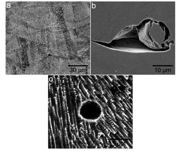
In addition to the cracks, bonding defects and micro-pores are also observed in the SLM specimen, as shown in Fig. 9. Due to the essential of SLM technique, the manufacturing progresses with the attachment of molten powders on the solidified layer during deposition [14]. However, completely melt may be unachieved at the corner of the laser profile where the minimum laser energy exists leading to insufficient heat flow to melt the bottom of the powder [44]. Thus, the arc-shape debonding generates between the bottom of the melt pool and solidified surface, as shown in Fig. 9(a). Besides, some small powders exist in the shadow of large powders which makes them hard to be melted because of restricted heat via point contact from the large powder exposed on the laser directly. That is the case revealed in Fig. 9(b).
Fig. 9. (a, b) Bonding defects and (c) pore in SLM alloy.
Fig. 9(c) shows a pore in SLM specimen. It has been investigated that the formation of pores in AM parts partly depends on the quality of raw powders [52,59]. Compared with PREP technique, powders prepared through argon atomization (AA) process generally contain a certain fraction of hollow particles (inner spherical pores) corresponding to entrapped gas during the process. These pores may not be eliminated completely and contribute to the pore formation in SLM alloy. However, both results (see Fig. 1(c) and (d)) from our work and Ref. [59] show that hardly any inner pores can be found in PREP processed powders. Thus, it is clear that pores in SLM specimen are not inherited from the raw powders. Here, we rationalize this kind of defect to the interaction between laser and powders during the deposition based on the work described in Ref. [60]. In which two mechanisms have been established to reveal how the strong dynamical melt flow generates pore defects. One is that the melt-flow on both sides of the laser track move towards the center under the increasing surface tension which enhances the possibility of trapping gas bubbles leading to the formation of pores at the bottom of a melt pool. Another possible mechanism is due to the vortex following the depression when the laser turned off. Some gas bubbles could be enveloped forming pore defects and/or seed a bigger pore via pore coalescence. Meanwhile, the liquid front at the bottom of melt pool can also catch the bubbles brought by vortex and freeze it into pores during the transformation from liquid to solid. One of or both these two mechanisms work and contribute to the formation of pores in the current case.
On the basis of aforementioned results, it seems to be unacceptable to process PM nickel-based superalloy using SLM technique from the perspective of precipitation hardening. However, for the conventional PM alloy, the super-solvus solution can dissolve the primary γ’ precipitates and re-precipitate inside the grains during solution cooling and subsequent aging which enables us to further tune the volume fraction and size distribution of γ’ precipitates [61]. In this research, this heat treatment strategy is applied upon the SLM and PM alloys. Fig. 10(a) shows that after heat treatment a high density of cuboid γ’ precipitates comparable to the PM counterpart (Fig. 10(b)) can be observed in SLM alloy. Their size, volume fraction and spatial distribution are quite similar to that in PM alloy, implying that the strengthening effect could be achieved in the viewpoint of precipitation strengthening mechanism [1,5]. Based on the image analysis, the average size of γ’ precipitates in SLM and PM alloy are 143.3 ± 4.0 nm and 149.5 ± 3.0 nm and the volume fraction based on the two-dimension SEM images are 51.1%±0.3% and 51.4%±0.6%, respectively. The typical microstructures like melt pools and cell structures in SLM specimen disappear during heat treatment.
Fig. 10. Microstructures in SLM and PM alloys after heat treatment: (a, b) the γ’ precipitates for SLM and PM alloys; (c, d) EBSD IPF maps obtained on the XY and XZ planes in SLM alloy; (e) EBSD IPF map for PM counterpart.
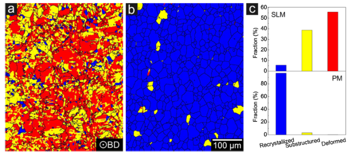
Obviously, grain microarchitectures are re-organized in both heat treated alloys (Fig. 10(c)-(e)). In the case of SLM one, the evolution in grain structures progresses through static recrystallization process primarily due to the presence of large stored stain result in an unstable state [24], namely, extensive substructured and deformed microstructures survive prior to heat treatment, as evidenced in Fig. 4, Fig. 11. It is also excepted that grain growth occurs following recrystallization during heat treatment (Fig. 10(c) and (d)). As a consequence of recrystallization, the grain orientation becomes more random comparing to that prior to heat treatment, as verified by the pole figure in Fig. S4(a). However, the columnar grains with high aspect ratio still present in this condition. In comparison, grain growth dominates over recrystallization in the PM one due to limited stored strain resulting in obvious large grain size after the heat treatment [62]. And the equiaxed grains are still the dominant microstructural feature in this alloy. Interestingly, a higher fraction of annealing twin (Fig. 10(c) and (d)) is observed in SLM specimen while this characteristic is hardly found in its PM counterpart. This difference has been analyzed in detail and associated results are offered in the next section.
Fig. 11. Recrystallization maps prior to heat treatment: XY plane for (a) SLM alloy and (b) PM alloy; (c) corresponding fraction distribution of recrystallized, substructured and deformed microstructures for SLM and PM alloys.
It is also interesting to find that the grain boundary precipitation of carbides and/or borides are so different in these two alloys during heat treatment. A stacked co-precipitation of carbide and boride are examined (W, Ti, Ta, Hf, C and B segregate to the product, see Fig. S5) in PM alloy. Instead, only boride enriched with Mo, W, Ta and B has been observed (Fig. S6) in SLM one and its size is much smaller than grain boundary product in PM counterpart. These differences are expected to be related to the manufacturing process inducing variation thermodynamic precipitation behavior of carbide and/or boride. However, the detailed discussion could not be presented in this work because the related data are supporting an ongoing research which will be published in the future.
Large amounts of annealing twins, whose boundaries are defined by a misorientation of 60° related to the <111> axis with a tolerance of 5°, are observed in heat treated SLM specimen, while extremely low fraction of annealing twin forms in PM counterpart, as revealed by Fig. 10(c) and (d). This phenomenon has also been observed in Ref. [63] but stopped without further detailed investigation on its formation mechanism. According to previous investigations, some possible mechanisms have been established to account for the formation of annealing twin. One is the stacking fault model in which annealing twins nucleate via stacking fault creation generating a new orientation to enlarge the driving force or improve the mobility of grain boundary, both of them are beneficial for the grain growth [64]. Another is the growth accident model where annealing twins are formed by a two-dimensional nucleation process on the {111} plane of the growing grains [65]. It has been evidenced [66] that the recrystallization process could promote the formation of annealing twin due to the large driving force enhancing the grain boundary migration velocity, which leads to an increase in twin density. In contrast to the recrystallization regime, the twin density decreases continuously during grain growth procedure caused by the insufficient driving force. As revealed above (Fig. 4), both grain boundary and KAM maps show that large stored strain remains in SLM specimen (higher amount of LAGBs and KAM value), in other words, the substructured and deformed microstructures are the dominant characteristic in this alloy, as supported by Fig. 11(a) and (c) (only the data about XY plane in SLM alloy is provided to demonstrate the phenomenon). Thus, strongly recrystallization is excepted to occur during following heat treatment. This hypothesis is confirmed by the IPF map examined from the heat treated SLM specimen. As a result, extensive annealing twins form during the recrystallization process, see Fig. 10(c). However, the grains in PM one prior to heat treatment appears to be closer to the full recrystallized structure (Fig. 11(b) and (c)), i.e., extremely lower amount of substructured and deformed microstructures exist in this alloy. Consequently, grain growth dominates much over recrystallization leading to seldom generation of annealing twin. These annealing twins are expected to improve the mechanical strength as an additional strengthening factor in nickel-based superalloy and will be discussed in the following section.
(1)Due to the essence of SLM technique and the applied laser scanning strategy (scanning direction rotates by 67° between each layer), a heat flow conduction parallel to the building direction is achieved producing the prevalent columnar grains and associated <001> fiber texture in the SLM alloy. γ’ phase is undetected in SLM alloy while it develops in PM counterpart prior to heat treatment.
(2)Four types of defects are clarified in the present SLM alloy, namely, solidification crack, liquation crack, bonding defect and pore. The accordingly formation mechanisms have been discussed in detail.
(3)After heat treatment, strongly recrystallization occurs in SLM alloy driven by the large stored strain accumulated during deposition. More random orientation and weaker texture are observed as a result of recrystallization. In contrast, grain growth dominates the microstructural evolution in PM one.
(4)Upon the solution and subsequent aging treatments, γ’ precipitates are generated with comparable size and volume fraction, which in turn leads to the considerable hardness response in both alloys.
(5)Extensive annealing twins form during heat treatment in the SLM alloy which is related to the recrystallization process. The grain boundary migration velocity is enhanced by the highly substructured and deformed microstructures promoting the formation of annealing twin in this alloy.
This work was supported financially by the National Key Research and Development Program of China (No. 2018YFB0704100), the Outstanding Graduate Project of Advanced Non-ferrous Metal Structural Materials and Manufacturing Collaborative Innovation Center, the Funding from the Opening Project of State Key Laboratory of Nickel and Cobalt Resources Comprehensive Utilization, the Project of Innovation and Entrepreneur Team Introduced by Guangdong Province (No. 201301G0105337290) and the Special Funds for Future Industrial Development of Shenzhen (No. HKHTZD20140702020004). The authors would like to gratefully acknowledge the kind help of Prof. Yan Wang (School of Aeronautics and Astronautics, Central South University).

 WeChat
/
| 〈 |
|
〉 |