Search for articles:
Liu Liu , Jinlai Liu
Corresponding authors:
Received: 2019-03-1
Revised: 2019-04-1
Accepted: 2019-04-30
Online: 2019-09-20
Copyright: 2019 Editorial board of Journal of Materials Science & Technology Copyright reserved, Editorial board of Journal of Materials Science & Technology
More
Abstract
Low-cycle fatigue behaviors of Ni-base single crystal superalloys containing different Re contents have been investigated at 760 °C. During heat treatment, Re retards γ′ phases coarsening and equalizes the distribution of γ′ phases. As Re content increases, fatigue life increases and slip bands distribute more inhomogeneously. Moreover, adding Re not only reduces stacking fault energy of the matrix, but also promotes the element segregation to increase the lattice misfit. However, the larger lattice misfit does not lead to the formation of dislocation networks, but which activates dislocation movement and promotes dislocations cross-slip and climbing movement under high temperature and applied stress. On the other hand, with the addition of Re, cyclic deformation behaviors change from cyclic hardening to cyclic stability, mainly depending on a transformation of deformation mechanisms from slip bands cutting through γ and γ′ phases to stacking faults shearing.
Keywords:
Nickel-base single crystal superalloys are widely applied as the turbine blade materials in the aircraft engines and industrial gas engines due to high operating temperatures and excellent mechanical properties in service [[1], [2], [3]]. In order to improve the high temperature performance of superalloys and satisfy the demand for more-efficient turbine engines, some refractory elements such as W, Mo and Re are added into the superalloys, in which the element Re plays a significant role [4].
In fact, Re is an expensive element but it can enhance the creep resistance [5]. Re promotes γ/γ′ lattice misfit to become more negative by increasing the matrix lattice spacing [6,7]. The large misfit is helpful to form interface dislocation networks, which hinders dislocations to slip toward the interface and shear the γ′ phases, decreasing the creep rate and improving creep properties. However, Caron et al. [8] considered that the influence of the lattice misfit is complicated by temperature and stress, the increase of misfit caused by Re element may not be the main reason for strengthening alloys. Subsequently, Yeh et al. [9] pointed out that a large misfit can indeed form dislocation networks, but the change of the lattice misfit does not directly improve properties. Moderate addition of Re element promotes the formation of the Ni-Re bond and the segregation of more refractory elements into γ matrix, increasing the microstructure stability and the solid solution strength of alloys to improve creep property [[10], [11], [12]]. Summarizing these results, it can be seen that the reasons for Re improving the properties of the superalloys are still controversial, and the microscopic studies on Re are compared in different superalloy systems.
During actual service, the alloys are subjected to more complex temperature and cyclic loading. For approaching the real conditions of the blades, the low-cycle fatigue (LCF) tests are performed [13]. Focus on the effects Re on the LCF behaviors, Li et al. [14,15] compared the LCF behaviors and the dislocation configurations between 3Re and 0Re alloys at 25 °C, 750 °C and 900 °C. Regardless of the 3Re and 0Re alloys, dislocations only slip in the γ matrix at either 750 °C or 900 °C, and the addition of Re only contributes to promoting dislocation cross-slip and climbing. However, from our previous studies on the LCF behaviors and deformation mechanisms of another 3Re alloy, the dislocations structure at 980 °C are similar to the research of Liu et al. [16]. Notably, at 760 °C, a large number of dislocations and stacking faults shearing into γ′ precipitates are also the main deformation mechanisms of experimental 3Re alloy [17]. For our experimental alloys, the fatigue deformation mechanism of the alloys without Re is not clear enough to estimate the effect of Re on the LCF behaviors at intermediate temperature. Besides, Li’s research also pointed that the fatigue life of the 3Re alloy is nearly three times longer than the 0Re alloy at 750 °C, and the deformation behavior of the 3Re alloy presents cyclic stability rather than cyclic hardening in the 0Re alloy. Distinctions between two alloys in the fatigue life and deformation behaviors at intermediate temperature are larger than other temperatures. In addition, it is well known that Re significantly improves the mechanical properties of superalloys, especially high temperature properties. Actually, the service temperature of the blade is about 1000 °C while that of the serration is around 760 °C [18,19]. Therefore, it is necessary to explore the reasons of Re strengthened alloys and improved properties by controlling the Re content in one alloy at intermediate temperature.
In this study, a set of LCF tests at 760 °C have been performed on single crystal superalloys containing 0Re, 1.5Re and 3Re in order to clarify the effects of Re on LCF behaviors and discuss the damage and deformation mechanisms, respectively.
Three sets of experimental nickel-base single crystal superalloys containing 0 wt% Re (Alloy 0Re), 1.5 wt% Re (Alloy 1.5Re) and 3 wt% Re (Alloy 3Re) were prepared in a directional solidification vacuum furnace under a high thermal gradient, and the nominal compositions of the experimental alloys are listed in Table 1. The preparation of the [001] single crystal rods was used by pre-fabricated seed method, First, short bars with directions close to the <001> crystal orientation as seeds were put into the shell. Then, the three alloys were respectively melted in a vacuum induction and directionally solidified into single crystal rods. Subsequently, the crystal orientation of the cast rods was detected by electron backscattered diffraction (EBSD) technique, bars only within 10° deviations from normal orientation were selected for the LCF tests. The as-cast rods were cut into 84 mm in length and were received the heat treatment as follows: 1300 °C × 2 h air cooling +1120 °C × 4 h air cooling +1080 °C × 4 h air cooling +900 °C × 4 h air cooling.
Table 1 Nominal composition of experimental alloys (wt%).
| Specimen | C | Cr | Mo | Co | W | Ta | Al | Hf | Re | Ni |
|---|---|---|---|---|---|---|---|---|---|---|
| Alloy 0Re | 0.07 | 7 | 1.5 | 7.8 | 5 | 6.6 | 6 | 0.15 | 0 | Bal. |
| Alloy 1.5Re | 0.07 | 7 | 1.5 | 7.8 | 5 | 6.6 | 6 | 0.15 | 1.5 | Bal. |
| Alloy 3Re | 0.07 | 7 | 1.5 | 7.8 | 5 | 6.6 | 6 | 0.15 | 3.0 | Bal. |
The single crystal rods were machined into LCF specimens with a gauge length of 16 mm and a diameter of 6.5 mm. After machining, the gauge section and excessive arc segment were polished with 2000# sandpapers at a low speed and then subjected to mechanical polishing before LCF tests to prevent premature crack initiations at the surface machined scratches. The LCF tests were all conducted with an Instron8862 servo hydraulic testing machine, and were carried out under total strains control (Δεt/2 = 0.8%) using an extensometer mounted on the ledges of the specimens in air at 760 °C. A triangular waveform with a constant strain rate of 5 × 10⁻³ s-1 and a strain ratio of R=-1 were used. After fatigue tests, the surface morphologies and the slip patterns on the surface were observed by a JSM-7100 F field emission scanning electron microscope (SEM). In the following, the thin foils were cut normal to stress axis approximate 2 mm apart from the fracture surface, then mechanically thinned to 50 μm and electro-polished in a solution of 10% perchloric acid and 90% Alcohol. Microstructural observations of the specimens after fracture were performed on a JEOL JEM-2100 transmission electron microscope (TEM).
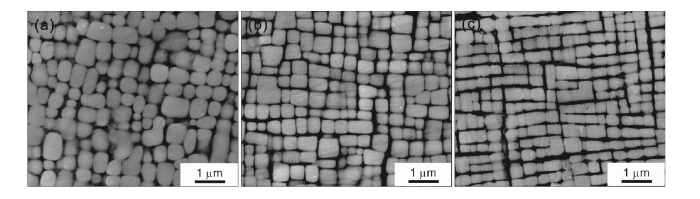
The microstructures of the Alloys 0Re, 1.5Re and 3Re after standard heat treatment are shown in Fig. 1. All of these alloys consist of γ′ precipitates and γ matrix, in which γ′ precipitates are the main strengthening phase of superalloys. With the addition of Re, the size of γ′ phases is smaller and more uniform, and the cubic γ′ phases orderly distribute in the alloys. It indicates that Re retards γ′ phases coarsening and equalizes the distribution of γ′ phases during standard heat treatment, which is similar to the reports by Giamei et al. [5].
Fig. 1. Microstructures of experimental superalloys containing different Re contents after standard heat treatment: (a) Alloy 0Re; (b) Alloy 1.5Re; (c) Alloy 3Re.
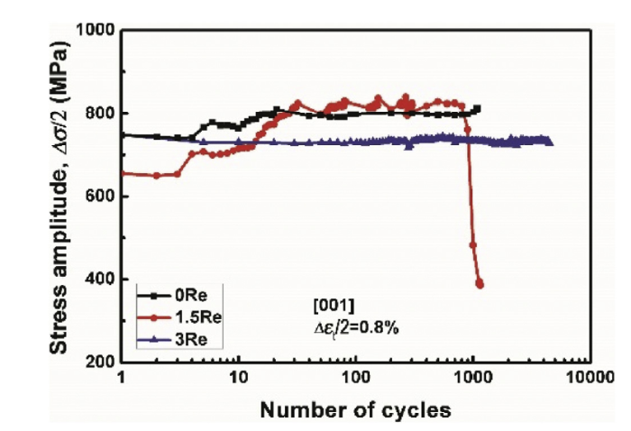
Fig. 2 shows the cyclic stress response curves of the Alloy 0Re, 1.5Re and 3Re under Δεt/2 = 0.8% at 760 °C during the LCF tests. The Alloy 3Re displays the longest fatigue life, while the fatigue life of Alloy 1.5Re is slightly longer than that of the Alloy 0Re. Nevertheless, both the Alloys 0Re and 1.5Re show initial cyclic hardening rather than cyclic stability of the Alloy 3Re, and the stress amplitudes of the two alloys are slightly higher than that of the Alloy 3Re. In the following sections, fracture surfaces, surface slip morphologies and dislocation configurations of the three alloys will be observed to explore the effects of Re on the LCF behaviors of single crystal superalloys.
Fig. 2. Cyclic stress response curves of experimental alloys containing different Re contents at 760 °C during LCF deformation.
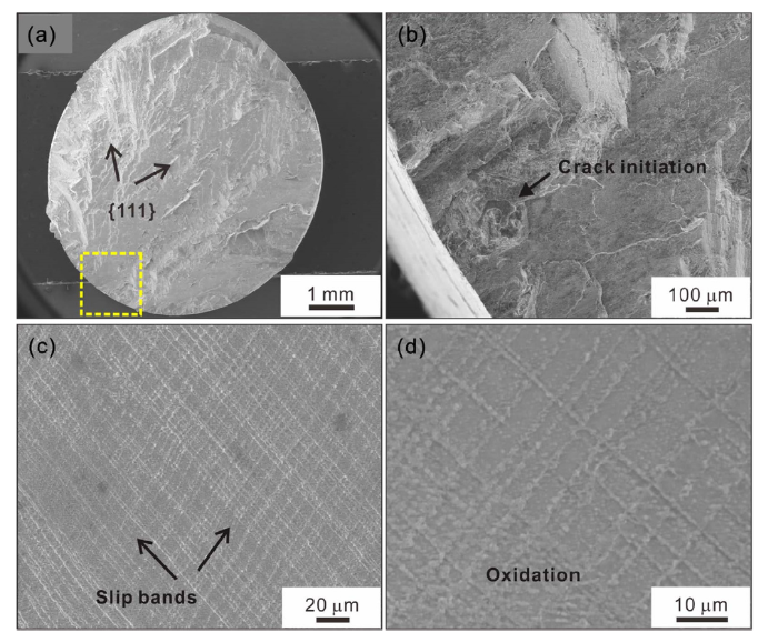
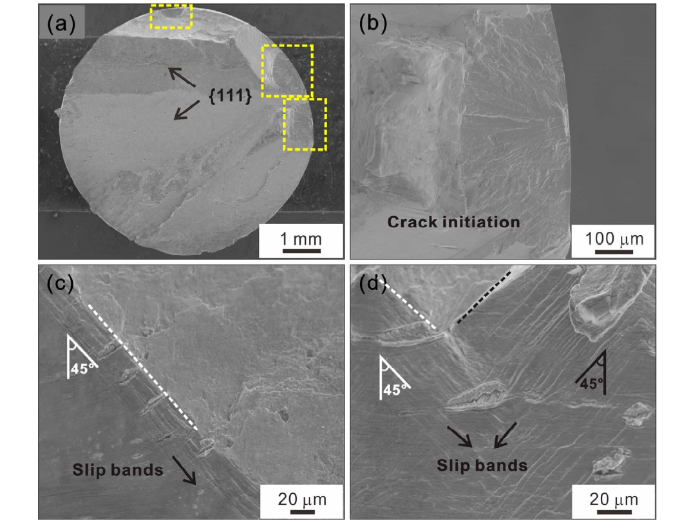
Surface morphologies of the Alloy 0Re after the LCF at 760 °C are shown in Fig. 3. The fracture surface is inclined to the stress axis and smooth with obvious river pattern, macroscopically (Fig. 3(a)). Cracks initiate from surface defects (Fig. 3(b)) and propagate along different two {111} slip planes. Moreover, two sets of slip bands with different directions appear on the surface, their directions are consistent with {111} slip planes that cracks extended, as shown in Fig. 3(c). Slip bands homogeneously distribute on the surface, accompanied by a certain degree of oxidation (Fig. 3(d)). Therefore, cracks of the Alloy 0Re fracture along crystallographic planes, and planar slip dominates the fatigue failure.
Fig. 3. Surface morphologies of Alloy 0Re after LCF failure at 760 °C: (a) fracture surface; (b) crack initiation (high-magnification of the yellow box indicated in (a)); (c) slip bands on surface; (d) oxidation (high-magnification of (c)).
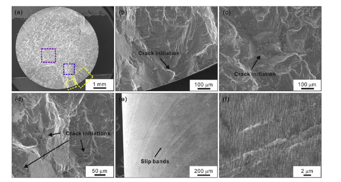
Compared with the Alloy 0Re, the fracture surface of the Alloy 1.5Re becomes more rough without obvious slip planes, and only has a small inclination angle to the stress axis macroscopically (Fig. 4(a)). The reason for this morphology is that not only cracks are originated from the fracture surface, but also internal defects affect the crack initiation and the propagation path (Fig. 4(b)-(d)). On the other hands, slip bands with only one direction appear on the surface for the Alloy 1.5Re, as shown in Fig. 4(e). Slip band spacing of the Alloy 1.5Re becomes larger and more inhomogeneous, as well as the number of slip bands decreases. Observed at high-magnification (Fig. 4(f)), slip bands shear γ′ phases in the diagonal direction.
Fig. 4. Surface morphologies of Alloy 1.5Re after LCF failure at 760 °C: (a) fracture surface; (b) crack initiation on surface (high-magnification of the yellow box indicated in (a)); (c, d) internal crack initiation (high-magnification of blue and purple boxes indicated in (a)); (e) slip bands on surface; (f) slip bands cutting γ′ phases.
For the Alloy 3Re, fracture surface is composed of different smooth facets and presents much more smooth than the Alloys 0Re and 1.5Re macroscopically, as shown in Fig. 5(a). Multiple crack initiations are generated from the surface observed in Fig. 5(b). However, compared to the Alloys 0Re and 1.5Re, slip bands observed on the surface greatly decrease. Only several slip bands occur near the fracture surface, and the directions of slip bands are paralleled to the main cracks (Fig. 5(c)). Moreover, at the junction of different fracture facets, slip bands with different directions (Fig. 5(d)) incline to the stress axis with nearly 45° angle, respectively. It implies that the main crack fractures along {111} crystallographic planes, and planar slip still plays an important role in fatigue failure.
Fig. 5. Surface morphologies of Alloy 3Re after LCF failure at 760 °C: (a) fracture surface; (b) crack initiation (high-magnification of the yellow boxes indicated in (a)); (c) slip bands parallel to surface; (d) slip bands at junction.
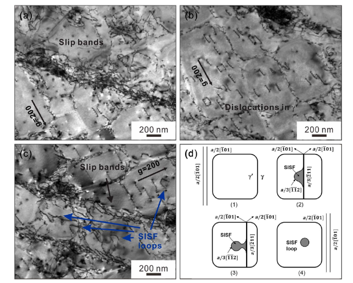
Microstructural configurations of fatigued Alloy 0Re at 760 °C are performed in Fig. 6. A number of slip bands along the <011> direction continuously cut through γ and γ′ phases (Fig. 6(a) and (c)). High density of tangled dislocations limited to the slip bands causes the uneven deformation during the LCF, which generates considerable strain localization and leads to work hardening. This dislocation configuration is attributed to the planar slip [20,21], and it is generally believed that the planar slip is the dominant deformation mechanism for the face centered cubic (FCC) metal in low and medium temperature ranges [22,23]. Meanwhile, many dislocations shear into γ′ precipitates, as shown in Fig. 6(b). Apart from this, some fault loops in the γ′ precipitates can be seen in Fig. 6(c), the formation mechanism of which is described schematically in Fig. 6(d). The a/2 < 101> dislocations combine to form an a<101> superdislocation at the γ/γ′ interfaces, then shear into γ′ precipitates and dissociate into two a/3 < 112> dislocations and superlattice intrinsic stacking fault (SISF). The trailing a/3 < 112> dislocation is pinned, and a fault loop is left in the γ′ precipitates by Orowan mechanism. Then the original a/2 < 110> dislocations are separated because of lower antiphase boundary (APB) energy [[24], [25], [26]]. Therefore, the predominant deformation mechanism of the Alloy 0Re at 760 °C includes slip bands, dislocations shearing γ′ precipitates and fault loops.
Fig. 6. TEM bright-field micrographs showing dislocation configurations of Alloy 0Re after fatigue failure at 760 °C: (a) slip bands; (b) dislocations in γ′ phases; (c) fault loops; (d) schematic illustration of formation of fault loops.
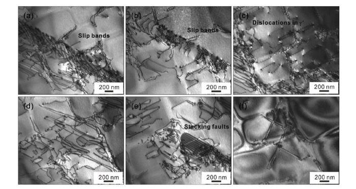
The TEM observations of the Alloy 1.5Re after fatigue at 760 °C are shown in Fig. 7. Dislocation configurations of the Alloy 1.5Re consist of a large number of slip bands, dislocations shearing γ′ precipitates, stacking faults and dislocations slipping in the γ channels. Morphologically, compared with the Alloy 0Re, the dislocation density in the Alloy 1.5Re is lower and dislocation alignment is more orderly in each slip band, but the width of slip bands is much larger (Fig. 7(a) and (b)). Furthermore, the number of dislocations shearing into γ′ precipitates in the Alloy 1.5Re are less than that in the Alloy 0Re, as shown in Fig. 7(c). Besides, a great number of dislocations slip paralleled to the (001) planes and present long and narrow shaped dislocation loops in the γ channels, which are only observed near slip bands (Fig. 7(d)). Apart from this, the stacking fault energy of the matrix decreases when Re is added, stacking faults in γ′ precipitates (Fig. 7(e)) prevent the movement of the following dislocations effectively. Remarkably, an interesting dislocation configuration is demonstrated in local areas, as shown in Fig. 7(f). Dislocation traces cross each other and have a 90° reorientation, and the width between two parallel dislocations is very small. This type of dislocations originates from the leading dislocations cross-slip in the horizontal γ channels, and leaving mixed dislocations at the γ/γ′ interfaces. Meanwhile, cyclic tensile and compressive stresses promote leading dislocations to move forward or backward [27,28]. Similar dislocation configuration has been reported in other single crystal Ni-base superalloys and it belongs to wavy slip [29]. It means that the deformation mechanism of the Alloy 1.5 Re is dominated by planar slip, but it is also accompanied by partial wavy slip.
Fig. 7. TEM bright-field micrographs showing dislocation configurations of Alloy 1.5Re after fatigue failure at 760 °C: (a, b) slip bands; (c) dislocations in γ′ phases; (d) dislocations slipping in γ channels; (e) stacking faults; (f) dislocation cross-slip.
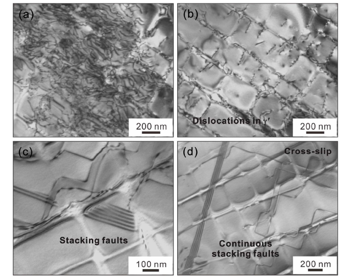
The dislocation configuration of the Alloy 3Re at 760 °C in Fig. 8 is remarkably different morphologies. Fig. 8(a) shows a great number of dislocations inhomogeneously in the matrix. Many dislocations and stacking fault shear into γ′ precipitates, as shown in Fig. 8(b) and (c). Notably, the stacking faults energy of the matrix reduces owing to the addition of Re element, the continuous stacking faults extending through γ and γ′ phases are only presented in the Alloy 3Re (Fig. 8(d)). The formation mechanism of the continuous stacking faults has been proposed in our last work [17]. Therefore, for the Alloy 3Re, the dominant deformation mechanism changes into a combined process of dislocation movement in the γ matrix, dislocations pairs shearing γ′ phases and stacking faults.
Fig. 8. TEM bright-field micrographs showing dislocation configurations of Alloy 3Re after fatigue failure at 760 °C: (a) dislocations in γ channels; (b) dislocations in γ′ phases; (c) stacking faults in γ′ phases; (d) continuous stacking faults extending through γ and γ′ phases.
As shown in Fig. 2, with the addition of Re element, the fatigue life increases under the same strain range at 760 °C. According to the microstructures after the heat treatment, Re retards γ′ phases coarsening and promotes γ′ phases ordering. In fact, the diffusion activation energy of Re in Ni is very high, and the diffusion activation energy of other elements in Ni increases as increasing Re contents [11,30], which means that the lower diffusivity of Re element may suppress the diffusion of other elements. In the Ni-rich matrix, a directional incompressible Re-Ni bond is formed between Re and Ni atoms, which strongly hinders the exchange of Re atoms and vacancies and retards most of diffusion-driven processes in the alloys. On the other hand, Re element mainly distributes in the γ matrix and promotes the segregation of more refractory elements into γ matrix, increasing the solid solution strength of alloys. As a consequence, adding Re increases the atomic bonding strength and the solid solution strength of alloys to retard γ′ phases coarsening and improve the properties.
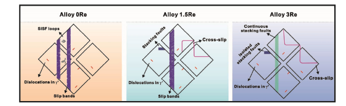
When the Re element is added, the difference of microstructure deformation mechanisms among the Alloys 0Re, 1.5Re and 3Re is strongly obvious, and the schematic illustration of deformation mechanisms after LCF tests at 760 °C has been concluded in Fig. 9. With increasing Re contents, the deformation features change from slip bands cutting through γ and γ′ phases to stacking faults shearing. It is well known that the addition of Re element reduces the stacking fault energy of the matrix, and the low stacking fault energy would facilitate the formation of stacking faults [[31], [32], [33], [34]]. Actually, the width of extended dislocations is large for the low stacking fault alloys, dislocations are not integrated to superdislocations slipping in different slip planes but are captured to form dislocation dipoles, finally reducing dislocation mobility and improving mechanical properties of the alloys. When the Re content is increased to 3 wt%, the stacking fault energy of the matrix is further reduced and a large number of stacking faults appear in the matrix, hindering subsequent dislocation movement in the γ channels and strengthening the alloys. On the other hand, the addition of Re element increases the lattice misfit of the alloys. Under the condition of high temperature and external stress, more misfit dislocations would promote dislocation cross-slip or climbing, facilitating dislocation interactions between different slip planes but hindering subsequent dislocations slipping to the interface. Nonetheless, the change of the lattice misfit is not enough to form interface dislocation networks, there are still a large number of dislocations cutting into γ′ phases. Therefore, the addition of Re promotes the formation of stacking faults in the matrix and the movement of dislocation cross-slip, which is also one of the reasons for the better fatigue performance of the alloys.
Fig. 9. Schematic illustrations of microstructure deformation mechanisms of Alloys 0Re, 1.5Re and 3Re after LCF tests at 760 °C.
As for the cyclic deformation behaviors, cyclic hardening observed in the Alloys 0Re and 1.5Re and cyclic stability observed in the Alloy 3Re are related to the resistance of plastic deformation for the alloy, including dislocation-dislocation interaction and dislocation-precipitate interaction [16,35]. A large number of dislocations interaction in the slip bands cause local stress concentration and promote cyclic hardening for the Alloys 0Re and 1.5Re. For the Alloy 1.5Re, a greater degree of cyclic hardening is indicated. The reasons include that the larger width of slip bands, less dislocations cutting γ′ precipitates and dislocations slipping only near the slip bands cause uneven plastic deformation and large stress concentration. Moreover, the stacking fault energy reduces as the Re content increases from 0 wt% to 1.5 wt%, which promotes the dissociation of the a/2 < 110> dislocations to form stacking faults and hardens the alloys. Besides, according to the observation of the fracture surface of the Alloy 1.5Re, there are many casting defects distribute on the surface and subsurface. When the crack propagation encounters internal defects, a part of energy will be consumed to change the expansion path, and the larger applied stress is needed to continue crack propagation. Inversely, for the Alloy 3Re, the stacking faults further reduce as the Re content increases to 3 wt%, so that a large number of isolated and continuous stacking faults form and strengthen the alloy. On the other hand, increasing Re content causes the increase of the lattice misfit, but it is insufficient to form the interface dislocation networks to hinder dislocations cutting γ′ precipitates. More misfit dislocations promote dislocation cross-slip under applied stress and reduce the resistance of dislocation movement in the matrix. Consequently, a large number of dislocations cross-slip in the matrix and leading dislocations shearing into γ′ precipitates reduce local stress concentration of the matrix, which offsets the hardening effect from stacking faults and dislocations tangled in local area, finally forming a dynamic equilibrium of the cyclic stability.
The LCF behaviors of single crystal superalloys containing different Re contents have been systematically investigated at 760 °C, and the variation of fracture and deformation mechanisms with the addition of Re has been proposed, and the effects of Re on the LCF behaviors have been analyzed in detail. The main conclusions are the following:
(1)The addition of Re element increases the microstructure stability of alloys, which is the main reason for the improvement of fatigue performance at 760 °C.
(2)The alloys containing different Re contents are mainly deformed by planar slip, and cracks fracture along the crystallographic planes at 760 °C. However, the density of observed slip bands is different as Re contents changes.
(3)Adding Re causes a transformation of the deformation mechanisms from slip bands cutting through γ and γ′ phases to stacking faults shearing. Moreover, the increase of matrix dislocation density and local cross-slip dislocations are the result of Re increasing the misfit of the alloys.
(4)Slip bands are the primary reason of cyclic hardening for the Alloys 0Re and 1.5Re. With respect to the Alloy 3Re, the cyclic hardening caused by stacking faults and the cyclic softening caused by dislocations cross-slip and shearing into γ′ phases combine to present cycle stability at 760 °C.
This work was supported financially by the National Natural Science Foundation of China (Nos. 51671188, 51571196 and 51601192) and the Shenyang Science and Technology Project (No. 17-101-2-00).
The authors have declared that no competing interests exist.

 WeChat
/
| 〈 |
|
〉 |