Search for articles:
Si-Mian Liu, Shi-Hao Li, Wei-Zhong Han
Corresponding authors:
Received: 2019-01-6
Revised: 2019-02-21
Accepted: 2019-02-28
Online: 2019-07-20
Copyright: 2019 Editorial board of Journal of Materials Science & Technology Copyright reserved, Editorial board of Journal of Materials Science & Technology
More
Abstract
Radiation-induced helium bubbles are detrimental to the mechanical properties of metals, usually causing severe hardening and embrittlement. Hexagonal close-packed (HCP) α-Zr alloys are one of the primary structural materials for nuclear applications, however, the effect of helium bubbles on their deformation and fracture behaviors still remains unexplored. Here, we found that ordered helium bubbles prefer to align along the basal plane in HCP α-Zr. Micro-scale in situ tensile tests revealed that helium bubbles less than 8 nm in size can increase the critical resolved shear stress of the prismatic slip. However, once the helium bubbles are larger than 8 nm, a bubble-softening effect happens due to a decrease in number density of helium bubbles and an increase in porosity. Once the Schmid factor of basal slip is considerably higher than prismatic slip, bubble coalescence along the basal plane becomes the major failure mode in helium-irradiated α-Zr.
Keywords:
Hexagonal close-packed (HCP) α-Zr and its alloys are widely used as cladding tubes for nuclear fuel in various nuclear power plants because of their small neutron-absorbing cross-sections, excellent corrosion-resistance and mechanical properties. As the first safety barrier in nuclear power plant, Zr alloys suffer severe fast neutron radiation [1]. Due to the (n, α) reaction in nuclear reactor, the effect of helium on the blistering and further erosion damage in Zr were also explored [2,3]. Because of wide applications in nuclear industry, it is of practical interest to study the mechanical properties of Zr and its alloys, especially after radiation damage.
HCP α-Zr single crystals have anisotropic mechanical properties. Unlike Mg and Zn, α-Zr has a c/a ratio of 1.59, which is less than the ideal c/a ratio of 1.633, hence the close-packed prismatic plane is the main slip plane [4]. In general, the prismatic slip is the easiest slip system at any deformation temperature [5]. Due to higher critical resolved shear stress (CRSS) and Peierls stress in basal slip than that in prismatic slip system, the basal slip system is difficult to be activated at room temperature [[6], [7], [8], [9], [10]]. Numerous evidences show that the {10-11}<11-23> or {11-21}<11-23> slip can be triggered under loading along c-axis, indicating that the < c+a > pyramidal slip is the secondary slip mode in α-Zr, which is beneficial for the deformation compatibility [[11], [12], [13], [14]]. Compressive twinning of {11-22}<11-2-3> and tensile twinning of {10-12}<10$\bar{1}$$\bar{1}$> are also observed in operation to accommodate plasticity at ambient or cryogenic temperatures [[10], [11], [12], [13], [14], [15], [16]].
During service in nuclear reactors, a large number of radiation defects are introduced into α-Zr. The accumulation of radiation defects has severe detrimental effects. One of typical radiation effects in α-Zr is radiation growth [[17], [18], [19], [20], [21]]. Without additional stress, radiation causes the cladding tubes to elongate along the axial direction and to shrink along the radial direction. This anisotropy growth in α-Zr corresponds to a volume conservation, which is different from the isotropic radiation swelling [[21], [22], [23]]. The mechanism of radiation growth is assumed to be a result of partitioning of the interstitial loops on the prismatic plane and the vacancy loops on the basal plane, thus shortening along c-axis and extending in all directions perpendicular to it in a hexagonal unit [[20], [21], [22], [23], [24]].
Radiation also changes the mechanical properties of α-Zr alloys. Radiation produces considerable radiation defects, such as dislocation loops, voids or bubbles, which are obstacles for dislocations. On one hand, radiation defects increase the CRSS of prismatic, pyramidal and basal slips, and lead to hardening and embrittlement [25]. On the other hand, dislocations remove dislocation loops along the prismatic or the basal slip channels, leading to local softening and strain localization [[26], [27], [28], [29], [30], [31]]. After neutron irradiation, α-Zr alloys were found to become isotropic because of the gap of the CRSS values of the prismatic, pyramidal and basal slip systems decreases [32]. Recent studies indicate that the dominated deformation mode change from prismatic slip to basal slip in neutron-irradiated Zr-2.5Nb [32]. However, the mechanism of the radiation-induced isotropic plasticity and the basal slip dominated deformation are unclear. Therefore, the influence of various defects on the plastic deformation of HCP α-Zr requires further investigation.
In this study, we explore the effect of ordered helium bubbles on the deformation and fracture behaviors of α-Zr single crystals. Helium bubbles, one of typical radiation defects, can induce significant hardening, swelling and embrittlement in metals [[32], [33], [34], [35], [36], [37], [38], [39], [40], [41], [42]]. Recently, helium bubbles are found to be active dislocation sources in Cu, which promote the bubble-dislocation interactions and enhance the deformability of small-volume Cu [43]. However, the effect of helium bubbles on the deformation and fracture behaviors of HCP α-Zr remains unknown and requires further investigation. The outcomes of this study could be beneficial to the understanding on the plastic deformation mechanism in neutron irradiated α-Zr.
High-purity Zr (99.99 wt%) with 130 ppm oxygen impurity was used as starting material. The as-received high-purity Zr is marked as A1. In order to increase the grain size, one piece of the as-received high-purity Zr was heat-treated at 800 °C for 72 h in a tube furnace (GSL-1400) with a vacuum higher than 4 × 10⁻⁴ Pa, and the new sample is labeled as A2. After heat treatment, the oxygen concentration is increased to 950 ppm in A2. The average grain sizes are 20 μm for A1 and 85 μm for A2, respectively.
Helium implantation was conducted directly on the transmission electron microscopy (TEM) thin foils. Disk-thin foils with diameter of 3 mm were prepared by the traditional method. Then the TEM foils were irradiated by 400 keV helium ions at different temperatures (A1 at 200 °C and A2 at 400 °C) to a fluence of 2 × 10¹⁷ ions cm-2 by using an ion implanter. The radiation temperature is monitored by a thermocouple, and the target temperature was kept as constant during implantation. The implantation lasted for 200 min, which corresponded to a radiation flux rate of 1.67 × 10¹³ ions cm-2 s-1. The radiation damage (in units of displacements per atom (dpa), orange) and helium distribution (blue) were estimated by using the stopping and range of ions in matter (SRIM) with the full damage cascades calculation mode [44] adopting an average displacement threshold energy of 40 eV for α-Zr, as shown in Fig. 1(a). To further tune the size of the helium bubbles, only the samples irradiated at 200 °C (A1) were further annealed using a high-vacuum furnace at 550 °C and 650 °C for 1 h, respectively. The oxygen concentration in these samples remains unchanged. Focus Ion Beam (FIB) is used to cut thin cross-sectional foils to examine the distribution of helium bubbles. As shown in Fig. 1(a), the SRIM predicted helium concentration is consistent with the distribution of helium bubbles.
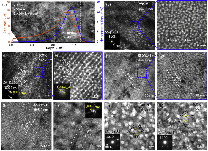
Fig. 1. (a) Cross-section TEM image of helium-implanted α-Zr. The variation of the radiation damage (orange curve) and the helium concentration (blue curve) with depth is estimated by SRIM. The peak helium concentration locates between two white dotted lines in (a); (b, d) high density of helium bubbles with an average diameter of 2.2 nm in α-Zr irradiated at 200 °C. (c, e) enlarged images of dashed squares in (b) and (d), respectively. The inserts in (d) and (e) are selected diffraction and FFT patterns, which indicate ordered helium bubbles structure; (f) ordered helium bubbles with average size of 4.1 nm in α-Zr after annealing at 550 °C for 1 h; (g) enlarged TEM image of helium bubbles in (f); (h) ordered helium bubbles with an average diameter of 6.2 nm in α-Zr after annealing at 650 °C for 1 h; (i) HRTEM image of helium bubbles in (h). The FFT pattern inserted indicates the reserved bubble superlattice after annealing treatment; (j, k) faceted helium bubbles formed in α-Zr after helium implantation at 400 °C.
Dogbone-shaped tensile samples were fabricated away from the grain boundaries for nanomechanical testing. The tensile samples had a gauge length of 1 μm, a width 425 ± 15 nm and a thickness 140 ± 40 nm, as listed in Table 1. Helium bubbled Zr (HB-Zr) samples were cut from the peak helium concentration region (at the depth of 0.8-1.2 μm). Full-dense Zr (FD-Zr) samples were cut from the region beyond the helium implantation, for example, 10 μm from the implanted surface. In situ tensile tests were performed by a Hysitron PicoIndenter (PI95) inside an FEG JEOL 2100 F TEM (200 kV) under displacement control at room temperature. The loading rate is 5 × 10⁻³ s-1. Real-time observation of the tensile deformation was recorded by a charge-coupled device camera. More than 40 tensile tests were performed on α-Zr single crystals with and without helium bubbles.
Table 1 Information of loading orientation for tensile test, Schmid factor of slip systems, sample size, bubble diameter and their average spacing, failure mode and net variation of critical resolved shear stress (CRSS). The samples in each line are tested in one in situ TEM session, and they contain the same level of oxygen impurity, thus the net strengthening effect from helium bubbles can be determined.
| Tensile direction | Schmid factor | FD-Zr | HB-Zr | ΔCRSS (MPa) | d (nm) | l (nm) | ls (nm) | Schematic diagram | ||||||
|---|---|---|---|---|---|---|---|---|---|---|---|---|---|---|
| P | B | π | Fracture plane | a (nm) | b (nm) | Fracture plane | a (nm) | b (nm) | ||||||
| [11$\bar{2}$0] | 0.433 | 0 | 0.405 | Prismatic | 420 | 132 | Prismatic | 420 | 180 | 80 | 2.2 | 5.9 | 3.7 | 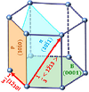 Prismatic slip (P):10-10<11-20> Basal slip (B):0001<11-20> Pyramidal slip (π):10-11<11-23> |
| [11$\bar{2}$0] | 0.433 | 0 | 0.405 | Prismatic | 420 | 165 | Prismatic | 420 | 123 | 259 | 6.2 | 7.4 | 1.2 | |
| [11$\bar{2}$0] | 0.433 | 0 | 0.405 | Prismatic | 430 | 182 | Prismatic | 410 | 108 | -87 | 16.3 | 24.5 | 8.2 | |
| [11$\bar{0}$0] | 0.433 | 0 | 0.405 | Prismatic | 430 | 152 | Prismatic | 440 | 156 | -112 | 29.4 | 53.2 | 23.8 | |
| [0$\bar{3}$35] | 0.117 | 0.385 | 0.461 | Random | 420 | 149 | Basal | 420 | 137 | 22.3 | 46.1 | 23.8 | ||
Fig. 1(a) shows the cross-section microstructure of the helium-implanted α-Zr at 200 °C. The radiation damage (orange curve) and the helium concentration distribution (blue curve) estimated by SRIM agree with the observed helium bubbles distribution. Only high density of helium bubbles is observed at the peak helium concentration region (12 at.%), as marked by the two dash lines in Fig. 1(a). The post annealing treatment after the radiation increases the size of the helium bubbles, while the ordering distribution of the helium bubbles remained the same. Fig. 1(b)-(k) highlights the helium bubbles formed in the peak helium concentration region after the implantation or the post annealing. Numerous spherical helium bubbles with a homogenous diameter (d) of 2.2 nm are formed in A1 sample (implantation at 200 °C). These bubbles distribute randomly when viewed along the [-12-11] zone axis, as shown in Fig. 1(b) and (c). When turning the zone axis to [-12-10], the alignment of the helium bubbles along the basal plane can be observed, as labeled in Fig. 1(d) and (e). The inserted diffraction and Fast Fourier transform (FFT) patterns in Fig. 1(e) indicates that the helium bubble superlattice is formed in α-Zr. The post-annealing at 550 °C or 650 °C does not change the ordered helium bubbles, while the size of helium bubbles increases slightly, as shown in Fig. 1(f)-(i).
The ordered helium bubbles disappear in the samples implanted at 400 °C (A2), as shown in Fig. 1(j) and (k). However, these helium bubbles still show a tendency of aligning along the basal plane (Fig. 1(j)). Instead of spherical helium bubbles, a high density of faceted helium bubbles with average diameter (d) of 22 nm is formed, as shown in Fig. 1(j) and (k). When viewing along < a > direction, helium bubbles have an elongated hexagonal shape bounded by facets of (0001) basal planes and (10-11} pyramidal planes (see Fig. 1(j)). In contrast, when viewed along the < c> axis, the helium bubbles exhibit an orthohexagonal shape with three facet planes corresponding to the first-order prismatic planes (see Fig. 1(k)). In addition, the radiation temperature has a stronger effect than the annealing temperature on the size of bubbles. The diameter of helium bubbles formed after implantation at 400 °C is two times of the size of the helium bubbles formed after annealing at 650 °C. In addition, the density of helium bubbles is lower, as shown in Fig. 1(i) and (k).
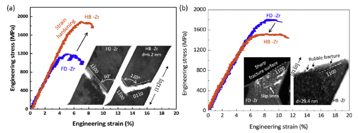
Helium bubbles can enhance the CRSS of the dislocations, and the strengthening effect is influenced by the size and number density of helium bubbles. To probe the effect of the helium bubbles on the slip behaviors in α-Zr, we conducted a series of in situ tensile tests on α-Zr single crystals containing different sizes of helium bubbles, all loading along < a>-direction. Fig. 2(a) shows a typical engineering stress-strain curves of α-Zr single crystals with (HB-Zr, blue curve) and without (FD-Zr, orange curve) helium bubbles. The average diameter of the helium bubbles (d) is approximately 6.2 nm in the HB-Zr. Obvious strain bursts appear in the engineering stress-strain curve of the FD-Zr, resulting from the activation and slip of the 1/3< -12-10 > dislocation on the prismatic plane. In contrast, the HB-Zr (orange curve) shows more stable deformation and an obvious strain hardening stage can be identified. The flow stress of HB-Zr is higher than the FD-Zr, corresponding to an obvious increase in CRSS of prismatic slip, such as, Δτ = 259 MPa. The inserted TEM images demonstrate the slip and fracture of FD-Zr and HB-Zr are all along the prismatic plane. The detailed tensile deformation can be found in Movies S1 and S2 in supplementary material.
Fig. 2. Typical engineering stress-strain curves for FD-Zr (blue curve) and HB-Zr (orange curve) with different bubble size. The black arrow indicates the trend of yield stress of FD-Zr and HB-Zr: (a) samples are fabricated from A1 (with an oxygen content of 140 ppm) and the diameter of helium bubble is 6.2 nm. The inserted TEM images are the corresponding fracture morphology of the FD-Zr and HB-Zr curves; (b) The samples were cut from A2 (with an oxygen content of 950 ppm) and the diameter of helium bubble is 29.4 nm. The inserts are the dark field image of the fracture surface of FD-Zr and the bright field image of the fracture morphology of HB-Zr.
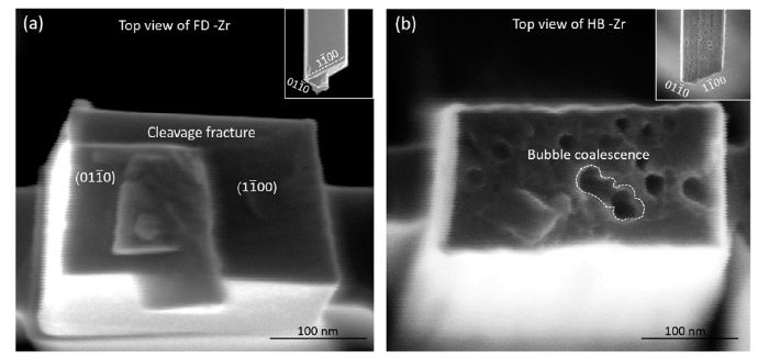
Similar in situ tensile tests are also conducted on α-Zr single crystals containing larger helium bubbles. Fig. 2(b) shows the tensile behavior of HB-Zr with an average helium bubble size (d) of 29.4 nm. Different from the flow behavior shown in Fig. 2(a), the HB-Zr displays softening and have lower flow stress than the corresponding FD-Zr. An obvious reduction in the CRSS of the prismatic slip appears for the HB-Zr containing large helium bubble, such as Δτ=-112 MPa. A slight increase in total ductility appears (plastic strain increased from 2.4% to 6.5%). Numerous dislocation activities across the sample can be identified before the fracture, as shown in Movie S3. The fracture of both the FD-Zr and the HB-Zr single crystals with larger helium bubbles is still along the prismatic plane, as indicated by inserted TEM images. The clear slip lines along {10 - 10} and {-1100} could be observed in FD-Zr in the image shown in Fig. 2(a). The fracture surface is sharp and flat. However, the HB-Zr shows ups and downs along the fracture surface in addition to some slip lines, as marked in the figure. Fig. 3 shows the typical SEM images of the fractured FD-Zr and HB-Zr (d = 16.3 nm). Both FD-Zr and HB-Zr demonstrate a similar fracture along the prismatic plane. A flat cleavage fracture surface forms in FD-Zr, as labeled in Fig. 3(a). In contrast, the top-view of the fracture surface in Fig. 3(b) shows many holes, which are indication of the coalescence of helium bubbles during the deformation and final failure in HB-Zr, as marked by the dash line. Mechanical data of the tensile tests with HB-Zr containing average bubble sizes of 2.2 nm and 16.3 nm are summarized in Table 1. Similar to the results shown in Fig. 2, the HB-Zr with a bubble size of 2.2 nm shows a hardening, while the HB-Zr with a bubble size of 16.3 nm shows a softening.
Fig. 3. Typical SEM images of fracture surface for FD-Zr and HB-Zr with loading axis of [
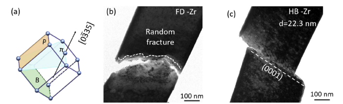
For the tests with prismatic slip system as the easiest deformation mode, the helium bubbles do not alter the failure mode of the HB-Zr except changing the CRSS. However, if the prismatic slip is not the favorable deformation mode, how is the effect of helium bubble on the deformation of α-Zr? With this question, we performed more tensile tests on the α-Zr single crystals with the basal plane located at the maximum shear stress plane, such as loading along the [0-335], as shown in Fig. 4 and Movies S4 and S5. The Schmid factor of the slip systems in this orientation was calculated and listed in Table 1. The HB-Zr and the FD-Zr demonstrate totally different fracture behavior. The FD-Zr has a wavy fracture front, as marked in Fig. 4(a), which is possibly induced by the activation of multiple slip systems. In contrast, the failure of the HB-Zr occurs along the basal plane (Fig. 4(b)), which forms a nearly flat fracture surface along basal plane. In general, the activation of the basal slip is very difficult at room temperature in α-Zr [[7], [8], [9], [10]], while the HB-Zr forms a near-cleavage fracture along the basal plane, which is also the plane of the formation of ordered helium bubbles (Fig. 1). We also performed other orientations with basal slip having the highest Schmid factor, in which similar fracture behaviors were displayed.
Fig. 4. Typical fracture surface of FD-Zr and HB-Zr (d = 22.3 nm) with loading axis of [
Our results indicate that the ordered helium bubbles have a significant effect on the deformation and failure of HCP α-Zr. In the following section, we attempt to rationalize these observations by discussing the formation mechanism of the ordered helium bubbles, the influence of the bubble size and spacing on the prismatic slip and the ordered helium bubble induced fracture along basal plane.
Several possible mechanisms have been proposed to explain the formation of the helium bubble superlattice [45]. Krishan suggested that the elastic interaction among bubbles induced by high internal pressure drives the helium bubbles aligning along specific crystallographic plane in order to minimize energy [46]. Recently, a phase-field model incorporating thermodynamic and kinetic properties based on experiments and atomistic simulations was conducted to show that the 1-D migration of self-interstitial atoms (SIAs), rather than the elastic interaction, is the primary mechanism for face-centered cubic (FCC) bubble superlattice formation in a body-centered cubic (BCC) metal [[47], [48], [49], [50], [51], [52], [53]]. Additionally, the planar diffusion of host interstitial atoms or dislocation punching from the over pressurized bubbles are considered to be the reason for the bubble superlattice [[54], [55], [56]].
Different from the FCC and BCC metals, the ordering of helium bubble in HCP Zr is typically aligning in two-dimensional layer parallel to the basal plane (Fig. 1) [57,58]. Previous experiments indicate that radiation-induced < a> interstitial dislocation loops preferentially align along the prismatic plane, and the radiation-induced vacancy clusters tend to be distributed on the basal plane [45,51]. The segregation of vacancies along basal plane in radiation is consistent with formation of ordered helium bubbles along the basal plane in Fig. 1. Therefore, the partitioning of SIAs/vacancies on the prismatic/basal planes is the fundamental reason for the formation of the bubble superlattice in α-Zr [[57], [58], [59], [60], [61], [62]]. According to the migration paths of point defects in HCP metals, SIAs prefer to migrate along the close-packed direction <11 - 20> or on closed-packed planes due to extremely low activation energies [58]. Therefore, non-uniform SIA planar fluxes move vacancies toward regions of lower SIA flux, such as the (0001) basal plane, which is called as the ‘Darwinian’ selection [57,63]. The vacancy has low effective migration energy on the basal plane, and the barrier for the in-basal plane migration is slightly lower than that of the off-basal-plane diffusion [58,59,64]. As a result, the partitioning of vacancies on the basal planes and the interstitials on the prismatic planes take place. The vacancies on the basal planes can combine with helium and cluster into ordered helium bubbles on basal plane. As such, a large number of vacancies accumulates on the basal planes, resulting in the crystal contraction (vacancy clusters collapsing) or swelling (helium bubbles) in the c-direction, which coincides with the atomistic mechanism of radiation growth in the α-Zr [65,66].
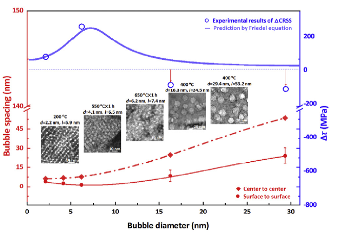
The FD-Zr and HB-Zr samples with the same oxygen concentration and tested in one TEM session are used to determine the net difference in CRSS (Δτ) induced by ordered helium bubbles. Fig. 5 plots the relationship between the net difference in CRSS (Δτ) and the helium bubbles character (bubble diameter and bubble spacing). The bubble spacing and bubble size are determined by measuring at least 5 TEM images. The average diameter of helium bubbles was obtained as follows:
d=2($\sum r^{2}_{n}$/n)1/2 (1)
where r is the radius of individual helium bubble and n is the number of helium bubbles. The spacing of helium bubbles (center to center) is determined by l = w/n, where w is the total length of the region with ordered helium bubbles. Accordingly, the average bubble spacing from the surface to surface is ls=l-d. As plotted in Fig. 5, with the increasing the diameter of helium bubbles, the l continuously increases, while the ls first slightly decreases then increases, and the turning point is at d = 8 nm. In contrast, the variation of ΔCRSS with helium bubble diameter is opposite, first increases and then decreases. It is clear that the size and spacing of helium bubbles have a significant effect on their strengthening behavior. In general, nanoscale helium bubbles are weak obstacles that obstruct the gliding dislocations. The increase in strength can be modeled by the Friedel-Kroupa-Hirsch theory [67,68]. For helium bubbles, the critical shear stress for passing a dislocation can be expressed as follows [69,70]:
Δτ=S×$\frac{2Γ}{bl_{s}}×cosφ^{3/2}_{c}$ (2)
where S is a constant close to 1, b is Burgers vector, ls is the spacing from surface-to-surface, ϕc is half of the critical bow-out angle when a line of dislocation is pinned by obstacles and Γ is the dislocation line tension. For the bowed-out dislocation, the line tension is as follows:
$Γ=\frac{μb^{2}}{4π}ln\frac{l}{r_{0}}$ (3)
Where μ is the shear modulus, r0 is the dislocation core radius of the obstacles, and l is the average spacing of obstacles on a dislocation line [71,72]. The cosine of the half of the critical bow-out angle can be identified as follows [68,70,73]:
$cosφ=\frac{ln\frac{α\bar{D}}{r_{0}}}{ln\frac{l}{r_{0}}}$ (4)
where α = 1-4 is the simulation factor (for weak obstacles, α = 1), $\bar{D}=\frac{1}{d}+\frac{1}{l}$ is the harmonic value of l and d, and d is the average bubble diameter. Substituting Eqs. (3) and (4) into Eq. (2), we obtain:
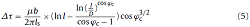
Fig. 5. Variation of bubble spacing and Δτ for prismatic slip vs. bubble diameters. The insets are images of helium bubbles with different sizes and spacing. The solid blue line is the prediction by the Friedel equation. The red solid fitting line and dotted fitting line are the variations of the spacing of surface-to-surface and spacing of center-to-center, respectively.
According to the Friedel equation, the magnitude of strengthening by helium bubbles can be calculated. The required input for Eq. (5) can be determined according to the TEM observation in Fig. 1, such as l, ls, and d, as listed in Table 1. For instance, for the tensile test of HB-Zr with bubble diameter of 2.13, by substituting l = 5.9 nm, ls = 3.767 nm, d = 2.13 nm and Δτ = 80 MPa into Eq. (5), we obtained ϕc = 77°, and a value of r0 = 1.08 nm was obtained according to Eq. (4).
For a similar group of helium bubbles, ϕc and r0 are constants. For HB-Zr with helium bubbles parameters of l = 7.37 nm, ls = 1.20 nm, and d = 6.17 nm, we obtained Δτ = 260 MPa, which is consistent with the experimental measurement of Δτ = 259 MPa. The variation of hardening with increasing the size of helium bubbles can be predicted by the Friedel equation, as plotted by solid line in Fig. 5. When the helium bubble size is smaller than 8 nm, a hardening effect is observed, while an inverse trend appears for the helium bubbles with sizes larger than 8 nm. For HB-Zr with d = 16.3 nm, a strengthening of Δτ = 59.5 MPa can be obtained, which is inconsistent with the experimental observed softening effect, such as Δτ = -87 MPa. Similarly, for HB-Zr with helium bubbles size of d = 29.4 nm, the prediction and the experimental observation have greater discrepancy, for example, Δτ = 25.3 MPa versus Δτ = -112 MPa. The difference between the modeling and the experimental measurement for HB-Zr with bubble larger than 8 nm are presumably due to a transformation of the deformation mechanism from bubble-dislocation interaction to bubble coalescence dominated failure, as revealed in Fig. 3(b). The large helium bubbles tend to coalesce to induce failure, which reduces the CRSS and introduce a softening effect. In general, the internal pressure of helium bubbles varies with their diameters [68,74], which may exert some effect on the deformation. According to Pbubble=$\frac{2γ}{ d/2}$, where γ is the surface energy and d is helium bubble diameter, the pressure of helium bubbles Pbubble with d = 2.2 nm, 6.2 nm, 16.3 nm and 29.4 nm, are Pbubble = 3 GPa, 1.05 GPa, 397 MPa and 220 MPa, respectively. With the decrease of internal pressure, the helium bubbles become softer, thus it can be cut through by dislocation easier, which is consistent with the experimentally observed bubble coalescence and softening effect in Fig. 3, Fig. 5. In addition, the HB-Zr with d = 29.4 nm shows better deformability (Fig. 2(b)). Helium bubbles paly a combined role in the dislocation obstacles and internal dislocation sources during plastic deformation [43]. With the increase of the size of helium bubble, the dislocation nucleation from the bubble surface becomes easier (τ∼1/d). Therefore, more dislocations nucleate and accumulate in the HB-Zr, which increases strain hardening and improves deformability.
The prismatic slip is the easiest deformation mode at room temperature in HCP α-Zr [[4], [5], [6], [7]]. The activation of basal slip requires much higher CRSS [[75], [76], [77]]. However, fracture along the basal plane is observed in the room temperature deformation of HB-Zr (Fig. 4). According to Table 1, all the HB-Zr samples showing fracture along basal plane have a higher Schmid factor for basal slip than for prismatic slip. Under low strain and at ambient condition, the basal slip is difficult to be activated in the α-Zr single crystal [6], hence a complex muti-slip mode is triggered, as shown in Fig. 4(a). Simulations suggest that the path of the basal slip is not straight, which includes three steps: the dislocation glides first in the prismatic plane, then crosses into the pyramidal plane, and finally back to the prismatic plane again, thus forming a complex cross-slip deformation [8]. Therefore, FD-Zr with basal slip favored for shearing displays a wavy fracture front. However, due to the formation of ordered helium bubbles on the basal plane, the walls between the helium bubbles can be easily cut off by the < a> or < c+a > dislocations, which promote bubble coalescence along the basal plane. Bubble coalescence boosts the formation of a large cavity [78,79], which further grows and extends, evolves into a crack and causes fracture along the basal plane in Fig. 4(b). These results indicate that the formation of ordered helium bubbles can significantly alter the deformation and fracture behaviors of HCP α-Zr.
The ordered helium bubbles are formed in HCP α-Zr after helium implantation at 200 °C. Ordered helium bubbles align along the basal plane, which coincides with the mechanism of radiation growth that vacancies prefer to accumulate along basal plane in α-Zr. The radiation temperature has a stronger effect on the bubble character than the post-annealing temperature. Through in situ tensile tests, we unveil that the size and spacing of helium bubbles have significant influence on the CRSS of the prismatic slip in α-Zr. With the increase of the diameter of helium bubbles, the Δτ first increases and then turns into decrease at a critical bubble diameter of 8 nm, which is caused by the alternation of deformation mode from dislocation-bubble interaction induced strengthening to bubble coalescence dominate plasticity. Once the basal slip is favored for shearing, the FD-Zr displays a wavy fracture front due to complex multi-slip, while the HB-Zr fractures along the basal plane because of bubble coalescences.
This work was supported financially by the National Key Research and Development Program of China (No. 2017YFB0702301), the National Natural Science Foundation of China (Nos. 51471128 and 51621063), the Innovation Project of Shannxi Province (No. 2017KTPT-12) and 111 Project of China (No. BP2018008).
Supplementary material related to this article can be found, inthe online version, at doi:https://doi.org/10.1016/j.jmst.2019.03.015.
The authors have declared that no competing interests exist.

 WeChat
/
| 〈 |
|
〉 |