Search for articles:
Naeem ul Haq Tariq , Tianying Xiong
Corresponding authors:
Received: 2018-09-24
Revised: 2018-11-19
Accepted: 2018-11-30
Online: 2019-06-20
Copyright: 2019 Editorial board of Journal of Materials Science & Technology Copyright reserved, Editorial board of Journal of Materials Science & Technology
More
Abstract
Cold spray additive manufacturing (CSAM) provides a potential solid state manufacturing route to fabricate variety of aluminum matrix composites (AMCs) with reduced possibility of undesired chemical reactions and residual thermal stresses. This study presents a hybrid (i.e. hot compression + hot rolling) post-deposition treatment to reinvigorate the mechanical properties of cold spray additively manufactured Al/B4C composites. The as-deposited samples were initially subjected to 30% thickness reduction via hot compression treatment at ~500 °C followed by a hot rolling treatment with 40% thickness reduction in 2 passes. Electron backscatter diffraction (EBSD) and high resolution transmission electron microscopy (HRTEM) results revealed that after hybrid post-deposition treatment (involving 70% accumulative thickness reduction), the aluminum grains in the matrix were extensively refined due to simultaneous operation of continuous dynamic recrystallization (CDRX) and geometric dynamic recrystallization (GDRX). Furthermore, interfacial defects were remarkably reduced while the nature of Al/Al and Al/B4C interfacial bonding was changed from sheer mechanical interlocking to metallurgical bonding which facilitated efficient transference of applied load to uniformly dispersed bimodal B4C particles. As a result, ultimate tensile strength (UTS) and elongation (EL) of the as-deposited sample were simultaneously improved from ~37 to 185 MPa and ~0.3% to 6.2%, respectively.
Keywords:
Boron carbide (B4C) reinforced aluminum matrix composites (AMCs) have attracted remarkable attention in automobile, aerospace, military, marine and electronic industries to fabricate variety of engineering components [1], [2], [3], [4], [5]. Additionally, high abundance of 10B isotope (possessing huge thermal neutron cross section) makes B4C reinforced AMCs an excellent choice to fabricate light weight neutron absorbing components required for efficient nuclear waste management [1,2,6]. In nuclear industries, several kinds of Al/B4C composites with the trade names, Boral, Metamic, Brotec, Holtec, Alcan, Maxus etc., are used to fabricate inner transportation baskets and casks for storing activated spent nuclear fuel [1,2,7]. Al/B4C composites are usually fabricated through liquid metallurgy (L/M) route (squeeze casting, spray casting, compo casting, stir casting etc.) or powder metallurgy (P/M) route (green compaction + sintering or hot pressing) followed by extrusion and/or rolling treatments. Nevertheless, traditional processing routs have their inherent shortcomings. For instance, P/M route is still far from being realized by the industry due to high processing cost, energy consumption and agglomeration of ceramic particulates. In contrast, L/M is cost effective processing route yet it has certain disadvantages associated with its high processing temperature. These include high level of porosity, residual thermal stresses and undesired interfacial reactions which further aggravate with increase in B4C content [5,8]. Consequently, functional and mechanical properties of the composite are highly degraded.
For the past few years, additive manufacturing processes, like powder bed electron beam melting (EBM), selective laser sintering (SLS), selective laser melting (SLM) and direct metal deposition (DMD) have attracted great attention to produce multi-functionality thick coatings/claddings or bulk deposits of ceramic reinforced composites [9]. However, these processes often result in the formation of heat affected zones, phase transformations and residual thermal stresses along with challenges of laser/electron beam reflectivity and limited sample dimensions [10]. In order to address aforementioned issues, there is ever increasing demands to explore new processing paths to fabricate Al/B4C composites for safer and efficient disposal of spent nuclear fuel.
In the past few years, cold spray additive manufacturing (CSAM) technique has emerged as a promising non-thermal processing route to produce bulk deposits of various kinds of alloys [10], [11], [12], [13], [14], [15] and composites [16,17]. In CSAM, bonding takes place due to severe plastic deformation of ductile powder particles impinged on the substrate with supersonic speed while the working temperature remains much below the melting point of feedstock particles. Therefore, oxidation, heat affected zones, thermal stresses and undesired chemical reactions are virtually avoided in the final deposit [16]. Moreover, CSAM provides several supplementary benefits when compared with traditional fabrication techniques. These include: (i) possibility of making dense composite deposits with theoretically no dimensional limitation, (ii) high deposition rate, (iii) flexibility of making various kinds of multi-materials and functionally graded materials irrespective of the stark difference in coefficient of thermal expansion (CTE), thermal conductivity, electrical conductivity or laser reflectivity of ingredient powders [10].
The above mentioned benefits make CSAM a competitive solid state processing method to fabricate Al/B4C composites for the nuclear industry. Generally, CSAM involves high pressure systems wherein helium and/or nitrogen gases are used to accelerate feedstock powder to achieve critical velocity for deposition. Consequently, manufacturing cost of the final product becomes too expensive to be commercialized thus making this process unappealing for the prospective industry. Under this scenario, employment of CSAM setup utilizing compressed air at medium/low pressure offers much more flexibility and cost benefits. However, the final deposits in this case have weak inter-splat bonding and relatively higher level of porosity which require post-deposition heat treatments to improve the mechanical properties [5,15]. In case of thick composite deposits (i.e. > 5 mm), conventional sintering/heat treatments can only heal out low fraction of inter-splat defects thus resulting in marginal improvement in the mechanical properties [5,18].
Recently, Zhao et al. has demonstrated the fabrication of highly dense free standing Ni-Al bulk material through cold spraying coupled with cold-pack rolling [19]. Keeping in view the recent paradigm shift in cold spraying technology from traditional repairing/near-net shaping applications to fabricate free standing structural or functional components, it is of paramount importance to unearth innovative and cost effective post-deposition treatments to efficiently heal out splat boundaries and rejuvenate mechanical properties of CSAMed deposits. In this study, we propose a hybrid post-deposition (i.e. hot compression + hot rolling) treatment that could be effectively used to efficiently improve interfacial bonding and invigorate the mechanical properties of CSAMed Al/B4C composites.
Feedstock powder was prepared by blending 60 wt% Al (purity ≥ 99.83%, D50 ~ 30 μm; D50 represents average diameter of powder particles) and 40 wt% B4C (purity ≥ 97.4%, D50 ~ 5 μm) in a jar mill rotated at 100 rpm. In order to facilitate blending, ZrO2 balls (5 mm) were added in the jar mill. After 2 h, feedstock powder was removed from the jar mill and dried in oven at 80 °C for 10 h [5,20]. An in-house CSAM setup, utilizing compressed air as powder carrier-gas and accelerating-gas, was employed to deposit Al/B4C composite on rotating (6061 Al alloy) substrate. Process temperature and pressure were maintained in the range of 2.2-2.3 MPa and 300-350 °C, respectively. To achieve thick deposit of Al/B4C, robot controlled spray gun was moved at a traverse speed of 5 mm/s above the substrate at a stand-off distance of 15 mm. The whole detail of CSAM process and operating parameters are provided elsewhere [5,20]. After spraying operation, Al/B4C deposit was carefully removed from the substrate by electric discharge machining (EDM) and sliced into free standing samples with dimensions 4.5 mm × 15 mm × 50 mm.
Free standing as-deposited composite samples were initially subjected to hot-compression (HC) treatment followed by hot rolling (HR) treatment. In hot-compression treatment, samples were compressed up to ~30% thickness reduction at ~500 °C at a constant crosshead speed of 0.05 mm/min. After hot-compression, samples were heated at ~500 °C in the furnace for 2 h and subsequently subjected to rolling treatment to further achieve 40% thickness reduction in 2 passes under constant rolling speed of 0.03 m/s. Samples were allowed to air cool after the rolling process. In order to maintain consistency, at least two samples were processed for each condition. Samples subjected to hot compression treatment were designated as ‘HC’ while those hot compressed and hot rolled were designated as ‘HC + HR’. The sequence of post-deposition hybrid treatment is schematically shown in Fig. 1.
Fig. 1. Schematic demonstration of hybrid post-deposition treatment alongside location of EBSD analysis and tensile test specimen.
Evolution of microstructures at each processing condition was characterized through electron backscatter diffraction (EBSD) system attached with Zeiss Merlin Compact scanning electron microscope. Specimens for EBSD analysis were cut from the central region of as sprayed, HC and HC + HR samples at the locations shown in Fig. 1. Samples were ground, polished using standard metallographic preparation procedures and scanned in X-Z plane with the step size of 150 nm. For further analysis, Oxford Instruments Channel-5 software was employed to analyze EBSD data. JEOL JEM-2100 F high resolution transmission electron microscope (HRTEM) was employed to reveal sub-structural and interfacial details. X-ray diffraction (XRD) of the as-deposited, HC and HC + HR samples was conducted using Philips X$\acute{P}$ert MPD diffractometer with Cu Kα radiation source. XS105 METTLER TOLEDO apparatus was used to measure experimental density (ρExp) of the samples at different processing stages. Theoretical density (ρTh) of the deposit was computed using the following relationship:
ρTh=Vp×ρp+(1-Vp)×ρm (1)
where Vp is volume fraction of B4C particles while ρp (2.5 g/cm3) and ρm (2.7 g/cm3) are densities of B4C and Al particles, respectively [5]. Image J software was used to estimate volume fraction of B4C in the deposit. Afterwards, apparent porosity (AP) of the samples was evaluated using formula [5,20]:
AP=$\frac{\rho_{Th}-\rho_{exp}}{\rho_{Th}}$×100 (2)
Mechanical properties of samples, processed at different conditions, were evaluated through tensile tests using INSTRON E1000 apparatus operated at a constant crosshead speed of 0.02 mm/min. Tensile test specimens (non-standard) [20] were cut from the central region of as-deposited, HC and HC + HR samples. The dimension and location of tensile test specimen is schematically shown in Fig. 1. Finally, fractured samples were investigated through scanning electron microscopy (SEM) to figure out the mode of fracture at different processing conditions.
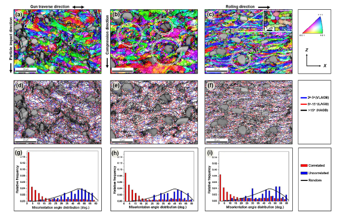
Fig. 2(a)-(c) shows color coded inverse pole figures (IPFs) super imposed on band contrast images of as-deposited, HC and HC + HR samples while Fig. 2(d)-(f) and (g)-(i) shows corresponding grain boundary maps (GBMs) and misorientation angle distributions (MADs), respectively. The as-deposited sample displays heterogeneous deformation of Al splats containing randomly oriented grains. Due to high strain rate deformation at splat boundaries, the grains located near the splat edges are stretched out and transformed into ultrafine grains through continuous dynamic recrystallization (CDRX) phenomenon [5]. The grains existing at splat interior are partially deformed and almost maintained their initial morphology (Fig. 2(a)). Besides, low indexed regions at majority of Al-Al and Al-B4C interfaces (highlighted by arrows) are observed which either indicate weak bonding, high defect density or lattice strain at the interfacial regions [21,22]. In contrast, HC and HC + HR samples led to increasingly high band contrast values (i.e. reduced fraction of low or un- indexed regions), indicating progressive reduction of inter splat defects and improved interfacial bonding [5,20]. The reduction of interfacial defects could be associated with enhanced diffusional activity facilitated by increased interfacial contact area of Al-Al and Al-B4C particles [19,20]. To validate gradual healing of inter-splat defects and improvement of interfacial bonding, apparent porosity of the samples was calculated. The porosity values of the samples under different processing conditions were in accordance with the microstructural observations. The as-deposited sample exhibited the highest porosity of 3.90% ± 0.03% [5,20], which was significantly reduced to 0.35%± 0.02% and 0.08% ± 0.03% for HC and HC + HR samples, respectively. It is also noticed that with increment in total thickness reduction from 30% (in HC sample) to 70% (in HC + HR sample), the distribution of B4C particles became more uniform within the matrix. Moreover, uniformly dispersed fragments of B4C (with size ranging from ~0.5 to 2 μm) emerged in the matrix.
Fig. 2. Color coded inverse pole figure (IPF) maps (a-c), grain boundary maps (d-f) and misorientation angle distributions (g-i) for as-deposited (a, d, g), HC (b, e, h) and HC + HR (c, f, i) samples.
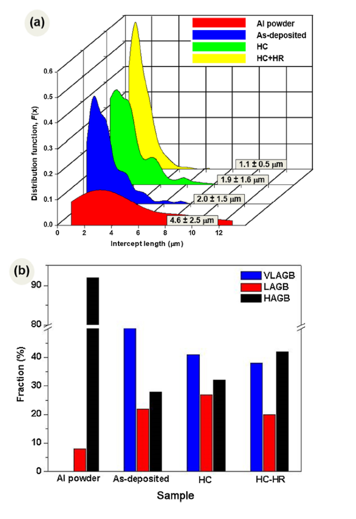
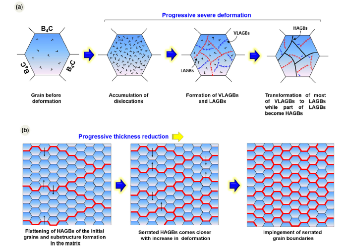
Fig. 3(a) presents a comparison of grain size distribution between as-received Al powder, as-deposited, HC and HC + HR samples. Compared with as-received Al powder, average grain size of Al matrix in as-deposited sample was sharply reduced from 4.6 ± 2.5 μm to 2.0 ± 1.5 μm. About 25% of the grains (mostly located at the edges of splat boundaries) were ~200-800 nm in diameter. In case of HC sample, equiaxed grains with size ~400-800 nm evolved throughout the matrix in the proximity of Al/B4C interfacial regions as highlighted by circles in Fig. 2(b). Due to large difference in thermal and mechanical properties between Al and B4C, high strain gradients were created in the vicinity of Al/B4C interfacial regions generating geometrically necessary dislocations (GNDs) [20,23]. The regions containing high density of GNDs are considered as potential sites for the nucleation of recrystallized grains through particle stimulated nucleation (PSN) phenomenon [24]. However, average diameter of Al grains remained almost same which could be associated with the dynamic grain growth (DGG) of already recrystallized grains [25]. This is quite clear from multi-modal grain size distribution curve of HC sample as shown in Fig. 3(a). For HC + HR sample, narrowly distributed (unimodal) grain size distribution curve was obtained indicating remarkable refinement and homogeneity of the microstructure (Fig. 3(a)). The average grain size for HC + HR sample was 1.1 ± 0.5 μm. Formation of uniform and highly refined microstructure in HC + HR sample could be associated with the simultaneous operation of PSN driven CDRX and geometric dynamic recrystallization (GDRX) phenomena as highlighted by a circle and a rectangle in Fig. 2(c), respectively. GDRX has been reported for aluminum and its alloys subjected to high strains at elevated temperatures [26]. Under severe hot deformation, initial Al grains in the matrix are considerably elongated (in the direction of plastic flow) which results in serrated grain boundaries with very high grain boundary area. Under continuous deformation, grain thickness is constantly decreased and finally arrives at a steady state. The moment size of serrations (associated with elongated grain boundaries) becomes comparable to the subgrain diameter, the serrated grain boundaries pinch-off to form so called GDRXed grains [26,27]. To serve more clarity, Fig. 4 schematically elaborates the mechanisms of grain refinement through CDRX and GDRX phenomena.
Fig. 3. Aluminum grain size distribution (a) and fraction of various types of grain boundaries (b) in as-received powder as well as in as-deposited, HC and HC + HR samples.
Fig. 4. Schematic demonstration of CDRX (a) and GDRX (b) mechanisms.
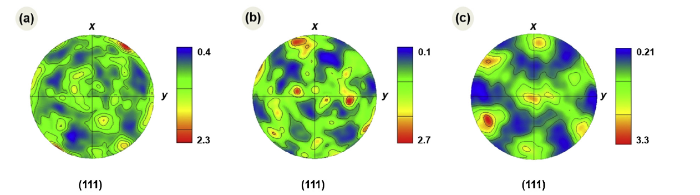
The GBMs, shown in Fig. 2(d)-(f), reveal that as-deposited sample is composed of heterogeneously distributed network of very low angle grain boundaries (VLAGBs, 2° < θ < 5°, blue lines; θ represents the misorientation angle), low angle grain boundaries (LAGBs, 5° < θ < 15°, red lines) and high angle grain boundaries (HAGBs, θ > 15°, black lines) [20]. With increase in thickness reduction (in HC and HC + HR samples), the fractions of VLAGBs, LAGBs and HAGBs are continuously changed while their distribution becomes increasingly uniform. The correlated MAD, analogous of point to point misorientation (or neighboring point’s misorientation) also confirms this observation (Fig. 2(g)-(i)). Fig. 3(b) presents a comparison of VLAGBs, LAGBs and HAGBs between as-received Al powder, as-deposited, HC and HC + HR samples. Compared with 0% VLAGBs, ~8% LAGBs and ~92% HAGBs in as-received powder, the as-deposited sample is composed of irregularly distributed ~50% VLAGBs, ~22% LAGBs and ~28% HAGBs, (Figs. 2(d) and 3 (b)). In as-deposited sample, high fraction of VLAGBs (mostly concentrated within highly deformed parent grains) is associated with the accumulation of strain energy (or formation of dislocations networks/cells) in the sample [28]. With thickness reduction of 30% (in HC sample), fraction of VLAGBs was abruptly decreased from ~50% to 40%, while fraction of LAGBs and HAGBs were augmented from ~22% to 28% and 28% to 32%, respectively. It is interesting to note that majority of LAGBs are present adjacent to VLAGBs. This reflects that a number of (thermodynamically) unstable dislocation networks/cells (characterized by VLAGBs) are converted in to lower energy configurations/sub-grains (characterized by LAGBs) through dynamic recovery (DRV) driven progressive re-arrangement of dislocations. Meanwhile, misorientation of sub-grain boundaries is continuously increased which finally resulted in transformation of a fraction of (either newly formed or already present) sub-grains in to fine recrystallized grains (characterized by HAGBs) [20,26]. For HC + HR sample, fraction of LAGBs is decreased from 27% to 20% and fraction of HAGBs is sharply increased from 33% to 42% while fraction of VLAGBs is slightly reduced to ~38%. This is consistent with the formation of equiaxed ultrafine grains in HC + HR sample through CDRX and GDRX phenomena. Furthermore, the uncorrelated MAD (analogous of point to origin misorientation) and MacKenzie distributions (i.e. theoretically calculated random distributions) are in good agreement for as-deposited and HC samples while a little disagreement is noticed in case of HC + HR sample, (Fig. 2(g)-(i)). The results suggest that the as-deposited and HC samples predominantly have random texture while HC + HR sample has very weak texture [23]. Fig. 5 shows (111) pole figures of the samples at different processing stages. Again, the as-deposited and HC samples show almost random texture with maximum intensity of ~2.3 and ~2.7 times of random, respectively. In case of HC + HR sample, very weak copper {112}<111> and goss {011}<100> texture components become evident in the pole figure for which maximum intensity was slightly increased to 3.2 times of random. In contrary to highly deformed Al and its alloys, the absence of strong rolling texture in HC + HR sample could be associated with evenly distributed B4C particles providing resistance to the deformation of Al grains in a favorable crystallographic direction [23,29].
Fig. 5. Pole figures of as-deposited (a), HC (b) and HC + HR (c) samples.
Kernel average misorientation (KAM) maps of different samples, showing variation in average misorientation (<5°) of a pixel with its entire first nearest neighbors, are shown in Fig. 6(a)-(c). Due to high degree of cold working in spraying operation, the as-deposited sample shows a dense population of unevenly distributed dislocation networks/lattice strains [5,20,30]. This is quite consistent with the presence of high fraction of VLAGBs in as-deposited sample (Figs. 2(d) and 3 (b)). With increase in deformation strain (in HC and HC + HR samples), cold working induced localized dense networks of dislocations were replaced by increasingly uniform distribution of dislocations. These dislocations could be anticipated as GNDs evolved as an outcome of the deformation incompatibility between matrix and particulate phases.
Fig. 6. Kernel average misorientation (KAM) maps for as-deposited (a), HC (b) and HC + HR (c) samples.
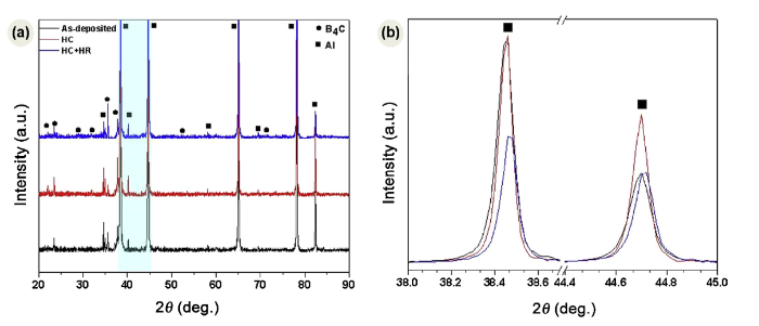
Fig. 7(a) shows XRD patterns of as-deposited, HC and HC + HR samples. In all samples, only diffraction peaks of Al and B4C are detectable, indicating that post-deposition treatments did not result in the formation of significant amount of undesired phases like Al3C, AlB2, AlB12C2, Al3BC, which are often formed in traditional L/M or P/M processes [2,23]. A close examination of XRD patterns reveals that Al peak intensities, their position and width are continuously changed with increase in the degree of deformation. Fig. 7(b) presents a magnified view of the shaded region marked in Fig. 7(a) showing obvious fluctuations in peaks intensity, position and full width at half maximum. This could be associated with change in dislocation density, lattice distortion and progressive grain refinement of the matrix at different stages [31].
Fig. 7. XRD patterns of Al/B4C composite at different processing stages (a) and magnified view of shaded region marked in
The microstructure of HC + HR sample was further analyzed using HRTEM. Fig. 8(a) shows representative image near interfacial region, showing well bonded and defect free Al/B4C interface. The selected area electron diffraction (SAED) patterns of regions 1 and 2 are provided as inserts in Fig. 8(a) that were identified as B4C and Al along [011] zone axis, respectively. The matrix grains near interfacial region are mainly composed of ultrafine grains with diameter ranging from 100 to 800 nm. As discussed above, these grains are anticipated to be formed as a result of PSN driven CDRX phenomena [23,24]. Moreover, few substructured grains (marked by arrow) with well-arranged arrays of dislocations are also observed. Fig. 8(b) presents a magnified view of region 3 in Fig. 8(a) and inserted Fourier transformation (FT) pattern. It shows that Al and B4C lattices are in intimate contact and Al/B4C interface is free from undesired phases like Al4C3, Al3BC and AlB10. It was noticed that there is an intermittent amorphous phase transition region (~4 nm in thickness) between Al and B4C, as demarcated with green lines in Fig. 8(b). Whereas, at few regions (marked by red lines), Al is directly bonded with B4C. The amorphous region between Al and B4C could be associated with damaged oxide layer left on powder particles after cold spraying process [32]. The microstructure of the matrix (captured away from B4C particles) reveals that Al grains are mainly composed of GDRXed and sub-structured grains with size ranging from 200 nm to 1.5 μm (Fig. 8(c)). Fig. 8(d) elaborates GDRX phenomenon (discussed earlier) wherein serrated grain boundaries (of highly deformed/elongated grains) pinch-off to form new (GDRXed) grains. The TEM observations are quite consistent with EBSD observation (Fig. 2, Fig. 3).
Fig. 8. (a) TEM bright field image for HC + HR sample near Al/B4C interfacial region (the top and bottom inserts show SAED patterns of B4C (location 1) and Al matrix (location 2)), (b) high resolution TEM image (with FT pattern inserted) for Al/B4C interfacial region at location 3, (c) TEM bright field image of matrix and (d) formation of GDRXed grains through impingement of serrated grain boundaries in matrix region.
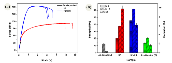
Fig. 9(a) shows room temperature engineering stress-strain plots for as-deposited, HC and HC + HR samples while Fig. 9(b) presents the summary of mechanical properties in the form of a bar chart. Clearly, HC (shown in red color) and HC + HR (shown in blue color) samples exhibit much better mechanical properties compared with that of as-deposited (shown in black color) sample. With 30% thickness reduction (in HC sample), the ultimate tensile strength (UTS) of the as-deposited sample is sharply improved from ~37 to 113 MPa while the elongation (EL) is ballooned from ~0.3% to 9.8%. In contrast, HC + HR sample (subjected to 70% accumulative thickness reduction) resulted in excellent trade-off between strength (185 MPa) and elongation (6.2%). In order to highlight the effectiveness of hybrid post-deposition treatment, mechanical properties of as-deposited sample subjected to conventional isothermal heating (at 500 °C for 4 h [5]) are presented in Fig. 9(b). Upon comparison with heat treated sample (shown in green color), hybrid treatment resulted in about three times higher UTS and four times wider EL [5]. Moreover, the mechanical properties of HC + HR sample are comparable with that of traditionally manufactured B4C/Al alloy composites. For instance, tensile strength of 20 wt% B4C/6061 Al composites fabricated by traditional P/M route has been reported to be ~188 MPa [33], while the same for B4C (15 vol.%) /A356.1 Al composite, fabricated via stir-casting process, has been reported from ~170-200 MPa [34].
Fig. 9. Room temperature engineering stress-strain curves (a) and comparison of mechanical properties of Al/B4C at different processing stages (b).
The microstructural and simulation results suggest that the superior mechanical properties of HC + HR sample are mainly attributed to the combined effect of the following factors: (1) progressive healing of inter-splat boundaries and defects due to reduction in diffusion paths with thickness reduction [19,20]; (2) progressive refinement of Al grains which resulted in high density of grain boundaries to impede dislocations motion (Hall-Petch strengthening) [35]; (3) formation of strong metallurgical bonds between Al-Al splats and Al-B4C interfaces that facilitated efficient transference of applied load from soft matrix to evenly distributed B4C particles (load transfer strengthening mechanism) [36]; (4) deformation induced accumulation and even distribution of GNDs in Al matrix (dislocation strengthening) [37]; (5) dispersion strengthening effect from fine B4C fragments with size < 1 μm (Orowan strengthening) [38].
The localized deformation behavior of the composite under different processing conditions was studied through microstructure-based crystal plasticity finite element analysis (CPFEA). In CPFEA, material’s point behavior in each grain is precisely calculated with deformation. The initial microstructure for the computational domain used in the simulation system is a result of image manipulation based on original EBSD image quality map. By using digital material representation (DMR) technique [39], microstructures were segmented based upon different grey scale contrast levels to distinguish different phases (i.e. pores, Al and B4C) and grain boundaries. The mesh was generated directly by transforming original pixel point into a quadrangle element and saving pixel gray level as cell state variable. Cell size can be defined as the corresponding pixel spatial size and total CPFEM calculation domain size equals 70 μm × 90 μm (initial domain height × width) areas in real material which contains 756 × 1052 square lattices. Finally, tensile tests were conducted with CPFEM in the simulation domain. Plane strain model and periodic boundary conditions were implemented in all simulations. The material constitutive relation was accomplished with the open source structured model DAMASK, which is served as a subroutine of commercial finite element software ABACUS. The model adopted for this study is a modification of a flexible and hierarchically structured model developed by DAMASK [40]. The material parameters for Al and B4C used in the model were obtained from the literature [41,42]. To investigate the deformation heterogeneity and effects of deformation on subsequent process, plane strain tensile with different deformation was adopted in the simulation. To satisfy the assumption that real material is composed of countless simulation domains in a periodic repeated arrangement, the multi-point constraints were applied at the surface of the representative volume element in ABACUS.
Fig. 10(a)-(c) shows Von Mises stress distribution maps for as-deposited, HC and HC + HR samples while Fig. 10(d)-(f) shows corresponding equivalent plastic strain maps. The stress distribution map of as-deposited sample was collected at strain interval of 0.25% while that of HC and HC + HR samples were captured at 5% applied strain. Clearly, in as-deposited sample the applied stress is highly localized and mostly concentrated at Al/B4C and Al/Al interfacial defects, as highlighted by arrows in Fig. 10(a). Consequently, matrix is in-homogenously deformed in few dominant (interconnected) shear bands to finally result in a catastrophic failure (Fig. 10(d)). In case of HC sample, the applied stress is moderately transferred to the matrix by the reinforcement (Fig. 10(b)). As a result, sample is evenly deformed with the formation of multiple intersecting shear bands, Fig. 10(e). For HR—HC sample, applied load is uniformly distributed among B4C particles (as evident by light green colored regions in Fig. 10(c)) and evenly transmitted to the matrix. This resulted in homogeneous distribution of plastic strain and formation of closely spaced multiple shear bands in the matrix, Fig. 10(f) [43]. This again indicates that with gradual increase in thickness reduction of as-deposited sample, Al/B4C and Al/Al interfacial bonding is progressively improved [20]. Consequently, applied load is efficiently transmitted from the matrix to the hard B4C particles. Fig. 10(g)-(i) shows stored energy maps for as-deposited, HC and HC + HR samples. The average energy stored in as-deposited, HC and HC + HR samples was estimated to be 0.005, 0.0489 and 0.0658 J/mol, respectively. In contrast to as-deposited and HC samples, the stored energy in HC + HR sample was higher which is evenly distributed/stored in ultrafine matrix grains in the form of GNDs. This may significantly contribute to the strength enhancement through work hardening phenomenon [37].
Fig. 10. Von Mises stress distributions (a-c), plastic strain distributions (d-f) and stored energy distributions (g-i) in as-deposited (a, d, g) at 0.25% strain interval, HC (b, e, h) and HC + HR (c, f, i) samples at 5% strain interval.
Fig. 11(a-i) presents SEM images of fractured surface for as-deposited, HC and HC + HR samples at different magnifications. As expected, the as-deposited sample displays mechanically bonded Al splats along with interfacial defects/pores (marked by arrow in Fig. 11(b)). Moreover, B4C particles with flat surface (marked by arrows in Fig. 11(c)) are evident, demonstrating the absence of metallurgical bonding between matrix and the reinforcement [5,20]. In line with simulation results, cracks were nucleated at weakly bonded Al-Al and Al-B4C interfaces at very low global stress values and rapidly propagated along weekly bonded splat boundaries which resulted in early stage de-cohesive fracture [18]. In contrast, fractured surfaces of HC and HC + HR samples show formation of shear ridges and dimple-like morphology which indicate ductile mode of fracture. In case of HC sample, relatively wide size distribution of dimples was noticed while fractured surface of HC + HR sample was composed of evenly distributed fine equiaxed dimple morphology (Fig. 11(d), (e), (g) and (h)). This is in agreement with grain size distribution (which is related with size of dimple [44]) discussed in Section 3.1. Fig. 11(e) and (f) indicated that at 30% thickness in HC sample, Al/Al splat bonding was not completely healed out while Al/B4C interfacial bonding is not strong enough to efficiently bear the applied load. The sporadic events of Al/Al and Al/B4C interfacial de-bonding are highlighted by arrows in Fig. 11(e) and (f), respectively. In contrast, virtually no splat de-bonding was noticed on the entire fractured surface of HC + HR sample. Additionally, well bonded fractured particles of B4C (marked by arrows in Fig. 11(i)) are noticed throughout the matrix which indicates that the matrix efficiently transmitted the applied load to the B4C particles. The above observations are completely in agreement with the equivalent stress and strain distribution results presented in Section 3.4. It seems B4C particles remained intact at their original positions under tensile loading. When the local stress exceeded fracture strength of B4C particle, micro-cracking of B4C particles took place which promotes micro-crack nucleation at Al/ B4C interface [23]. With continuous increase in the applied load, micro-cracks are generated at sharp edges (high stress concentration points, Fig. 10(c)) of B4C particles which continuously grow in their size and propagate in the matrix. Once all dominant cracks merge with the neighboring cracks, sample is fractured in a ductile manner [23,45].
Fig. 11. SEM images of fractured surface of as-deposited (a-c), HC (d-f) and HC + HR (g-i) samples at different magnification.
(1) This study presents a hybrid (i.e. hot compression + hot rolling) post-deposition treatment that could be used to efficiently enhance Al-Al and Al-B4C interfacial bonding, to achieve strength-ductility synergy, in Al/B4C composite. The as-deposited sample was initially subjected to 30% thickness reduction via hot compression treatment at ~500 °C followed by a hot rolling treatment with further 40% thickness reduction in 2 passes.
(2) At 30% thickness reduction (in HC sample), bonding between Al-Al and Al-B4C interfaces was significantly enhanced while multi-modal grain size distribution was obtained for the matrix with almost unchanged average grain size. In contrast, 70% accumulative thickness reduction (in HC+HR sample) resulted in extensively refined unimodal Al grains throughout the matrix due to simultaneous operation of CDRX and GDRX mechanisms.
(3) Microstructure-based CPFEA confirmed that hybrid post-deposition resulted in efficient transference of applied load to uniformly dispersed bi-modal B4C particles which resulted in homogeneous distribution of plastic strain and formation of closely spaced multiple intersecting shear bands in the matrix.
(4) Consequently, the strength (UTS) and elongation of the as-deposited sample was simultaneously improved from ~37 to 185 MPa and ~0.3% to 6.2%, respectively. In contrast to the isothermally heat treated sample, hybrid treatment resulted in about threefold higher strength and fourfold wider elongation.
This work was supported financially by the National Natural Science Foundation of China (No. 51671205).
The authors have declared that no competing interests exist.

 WeChat
/
| 〈 |
|
〉 |


