Search for articles:
Yuhong Zhao , Bing Zhang, Weipeng Chen
Corresponding authors:
Received: 2018-07-13
Revised: 2018-08-24
Accepted: 2018-08-26
Online: 2019-06-20
Copyright: 2019 Editorial board of Journal of Materials Science & Technology Copyright reserved, Editorial board of Journal of Materials Science & Technology
More
Abstract
In this study, the phase field method was used to study the multi-controlling factors of dendrite growth in directional solidification. The effects of temperature gradient, propelling velocity, thermal disturbance and growth orientation angle on the growth morphology of the dendritic growth in the solid/liquid interface were discussed. It is found that the redistribution of solute leads to multilevel cavity and multilevel fusion to form multistage solute segregation, and the increase of temperature gradient and propelling velocity can accelerate the dendrite growth of directional solidification, and also make the second dendrites more developed, which reduces the primary distance and the solute segregation. When the temperature gradient is large, the solid-liquid interface will move forward in a flat interface mode, and the thermal disturbance does not affect the steady state behavior of the directionally solidified dendrite tip. It only promotes the generation and growth of the second dendrites and forms the asymmetric dendrite. Meanwhile, it is found that the inclined dendrite is at a disadvantage in the competitive growth compared to the normal dendrite, and generally it will disappear. When the inclination angle is large, the initial primary dendrite may be eliminated by its secondary or third dendrite.
Keywords:
Directional solidification technology can control grain orientation, eliminate lateral grain boundaries and greatly improve the longitudinal mechanical properties of the material. Mullins and Sekerka [1] proposed the interface linear stability theory (M-S theory) using the perturbation analysis method. Warren and Langer [2] conducted a time-dependent semi-analytical numerical analysis of the stability of the flat interface by analyzing the evolution of the solute diffusion field at the interface front and theoretically revealed the time-dependent characteristics of the interface stability. Guo et al. [3] studied the regulation of lateral branches under the condition of random noise in the process of directional solidification under lateral branching and forced disturbance. Zhu et al. [4] used the phase field method to simulate the evolution of interface morphology under the condition of temperature gradient G = 20 K/cm of Ni-Cu binary alloy during directional solidification. Xing et al. [5,6] used phase field method to study the effects of anisotropic strength and pulling speed on dendrite growth direction under directional solidification, and further extended the growth direction selection (DGP) law. Noubary et al. [7] studied the effects of interfacial energy, diffusion coefficient and temperature gradient during directional solidification of ternary eutectic alloys by phase field method. Tourret et al. [8] studied the competitive growth of columnar crystals in two and three dimensions by phase field method. The results showed that the grain boundary orientation depends largely on the direction of primary dendrite growth. Pan et al. [9] used the phase field method to study the dendrite growth process in the pressurized solidification of Mg-Al alloy. The results show that with the increase of pressure, the growth rate of dendrites increases and the secondary dendrites are more developed. Wang [10] studied the dendrite growth process and stray grain distribution in laser surface-melted single crystal superalloy. The study of Hou [11] shows that thermal noise can trigger the growth of side-branch however it has no influence on the steady behavior of the dendritic tip. Echebarria et al. [12,13] used phase field method to study the formation of sidebranches under directional solidification of alloys. The results showed that sidebranches are caused by amplified noise and deterministic oscillations; Ghmadh et al. [13] used phase field method to study the growth directions and the stability of microstructures at various Peclet numbers under directional solidification conditions; Li et al. [14] used phase field method to study the microstructure evolution of dendrites with different orientations under directional solidification. Tourret et al. [15] used a three-dimensional dendrite needle network (DNN) model to simulate the directional solidification of Al-Si alloys and predict the main dendrite spacing at different growth rates, and was verified in experiments. Pereda et al. [16] analyzed the oscillation mode of cellular crystals during directional solidification in detail and studied the effects of growth parameters and crystal orientation on oscillation, their conclusions are consistent with Bergeon [17] and Tourret [18]. Amoorezaei et al. [19] studied the spacing selection during the directional solidification of Al-Cu alloy from two aspects of experiment and phase field simulation. Deschamps et al. [20] studied the relationship between the growth direction and the Peclet number by directional solidification experiments. Clarke et al. [21] studied the microstructure evolution of Al-Cu alloy during directional solidification by in-situ X-ray imaging and phase field method. Zhao et al. [22] used the phase field model to study the influence of different pulling speed on dendrite morphology under directional solidification conditions. As the pulling speed increases, the time of splitting of dendrite tip is advanced. Kang et al. [23] studied the influence of different pulling speed and interfacial energy anisotropy on the solute of the liquid phase channel of dendrite splitting under directional solidification condition by phase field method. Hou et al. [24] studied the effects of undercooling and microsegregation of Ni-Cu alloys by phase field model coupled with thermal perturbation. Zhao et al. [25] used the phase field model coupled with temperature field to study the effect of thermal coupling strength on the growth of pure Ni dendrites. With the increase of thermal coupling strength, the dendrite interface is disturbed and the secondary dendrite coarsens. During the directional solidification of Al-Zn alloy, Semoroz et al. [26] founded atypical <320> oriented dendrites and Gonzales et al. [27] observed seaweed-type morphologies at the beginning and end of this dendrite orientation transition (DOT).
However, systematic research on a variety of polymorphic advance mechanisms at the solid-liquid interface front of directional solidification under the coordinated control of temperature gradient and pulling velocity, thermal fluctuation and growth orientation angle has been lacking to date. Al-Zn alloy has a wide range of applications in the industrial field due to its excellent processing properties, light-weight and corrosion resistance. Furthermore, it has very rich microstructure morphologies in its solidification process. So we select the Al-Zn system to study the evolution of solid/liquid interface front in directional solidification process.
In this work, the directional solidification phase field model [28,29] was adopted to systematically study the metastable and stable morphology of the directional solidification interface front of an Al-Zn alloy, the regulation mechanism of solute redistribution on the solute segregation in the directional solidification interface front, the regulation mechanism of the temperature gradient direction on the growth orientation of the solid-liquid interface front, the phenomenon of multi-level dendrite morphology at the front of the solid-liquid interface which is induced by the interface advance speed, a large amplitude value of secondary dendrite phenomenon which is induced by the thermal disturbance, and the interface multi-stage dendrite arm competition mechanism which is controled by the solid-liquid interface growth orientation and heat flow direction synergistically in order to further explore the multi-factor regulation mechanism of the solid-liquid interface frontier advancement. The above phase field studies can also be applied to other alloys such as Al-Si alloys, Ni-Cu alloys, Al-Li alloys, etc.
The directional solidification phase field model [28,29] considers the solid diffusivity and uses a temperature freeze approximation (In the alloy heat diffusion is 10,000 times faster than solute diffusion, so the temperature field can be approximated to steady state), T=T0+G(z-Vpt), where z measures the distance along the growth direction from a reference point where the temperature T=T0, G is the temperature gradient, and Vp is the pulling speed.
First we define a dimensionless parameter u [30]
$u=ln\frac{C}{[C^{0}_{L}+C^{0}_{S}/2+\phi(C^{0}_{S}-C^{0}_{L})/2]}$ (1)
where ϕ is the phase field variable, C is the solute concentration, and $C_{S}^{0}$=ke$C_{L}^{0}$, $C_{L}^{0}$, CL0 are the solid/liquid equilibrium concentration, respectively. ke is the solute equilibrium partition coefficient.
Then the solute diffusion equation and the phase field evolution equation are as follows:
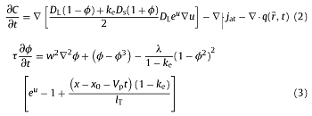
where DS, DL is the solid/liquid phase solute diffusivity; jat is the anti-trapping term [30], jat=-aϕw(1-ke) $ C_{1}^{0}$eu $\frac{∂ϕ }{∂t } $ $\frac{∂ϕ }{▽t } $; q (${\rightharpoonup \atop{r}}$, t) is the phase field disturbance term [31], <q($\rightharpoonup$ r,t), q($\rightharpoonup$ r,,t) >=2Fuδ($\rightharpoonup$ r-$\rightharpoonup$ r,)δ(t-t,), Fu is the thermal disturbance amplitude; Fu= $\frac{k_{B}T^{2}_{m}C_{P}}{L^{2}W^{2}_{0}}$ = $\frac{k_{B}T^{2}_{m}C_{P}}{L^{2}W^{2}_{0}}$ =$(\frac{d_{0}}{w_{0}})^{2}$, where kB is the Boltzmann constant, δ($\rightharpoonup$ r) is the Dirac delta function, τ is the relaxation time, w is the interface width; λ is the dimensionless phase field parameter, λ=a1w/d0 [32], where a1 = 0.8839, d0 is the solute capillary length, d0=-Γsl/[m(1-ke)$C_{ L }^{0}$], Γsl is Gibbs-Thomson coefficient; m is the liquidus slope of the alloy; x is the horizontal ordinate to the reference plane; x0 is the horizontal ordinate of the position of the tip of dendrite; lT is the thermal diffusion length [33], lT is expressed as lT=me (ke-1)$ C_{L}^{0}$ /$ G_{w_{0}}$.
The anisotropy of cubic symmetric crystals is introduced by w($\mathop{}_{n}^{→}$=$w_{0}$A($\mathop{}_{n}^{→}$), τ=τ0A($\mathop{}_{n}^{→}$)2 [34], where A($\mathop{}_{n}^{→}$) is expressed as A($\mathop{}_{n}^{→}$)=1+ε1(Q-3/5)+ε2(3Q-66S-17/7); Q, S is expressed as Q=$n_{x}^{4}$+$n_{y}^{4}$+$n_{z}^{4}$ and S=$n_{x}^{2}$$n_{y}^{2}$$n_{z}^{2}$, respectively.
In the simulation of this wrok, the calculation area is a rectangular of 768w0×96w0×96w0 (w0 is the initial interface thickness). The initial seed is placed at (0, ymax/2, 0), and the <100> crystal orientation of the dendrite coincides with the X-axis, the Y-axis, and the Z-axis of the three-dimensional Cartesian coordinate system. At the boundary of the calculation area, the phase field and concentration field are all subjected to Zero Neumann boundary conditions, namely:
$\frac{\partial \phi}{\partial n}$=$\frac{\partial C}{\partial n}$=0 (4)
where n is the boundary normal.
In this work, the finite difference method is used to solve the phase field evolution equation and the solute diffusion equation under the adaptive grid.
The research object of this paper is Al-0.5 wt%Zn alloy, and its simulation parameters are shown in Table 1:
Table 1 Material properties chosen for simulation.
| Property | Value in simulation |
|---|---|
| me (K·(wt%)-1) | -170 |
| ke | 0.45 |
| TM (K) | 933 |
| DL (m2·s-1) | 1.2 × 10⁻⁸ |
| DS (m2·s-1) | 1.2 × 10⁻⁹ |
| P (kg·m-3) | 2.9 × 10³ |
| Lf (J·mol-1) | 10676 |
To be accurate and convergent, the tip radius of the dendrite is at least 10 times the interface thickness [35]. The simulated minimum dendrite tip is about 10-6m, and R/w0=10, so the initial thickness of the interface is w0=1×10⁻⁷m. The relaxation time is the time required for the solute to diffuse from the solid phase to the liquid phase, which is related to the diffusion coefficient of the solute in the solid/liquid phase. According to the definition of the dimensionless solute diffusion coefficient ~DL=Deτ0/$w_{0}^{2}$, the value of the relaxation time τ0 can be determined. In the simulation, the value ~DL=5, then τ0=2.5×10⁻⁶s. In addition to the above important phase field parameters and material physical parameters, it is also necessary to set the disturbance amplitude, the simulation area size, the mesh refinement level, the supersaturation, and the interface advance speed, etc. These parameters are written to the input file after being dimensionless. In the simulation, Fortran90 and Microsoft Visual Studio 2010 are used to compile programs. The physical parameters, mesh node parameters, and mesh distribution parameters are written in three input files: parameter.dat, grid.dat and neighbor.dat, respectively.
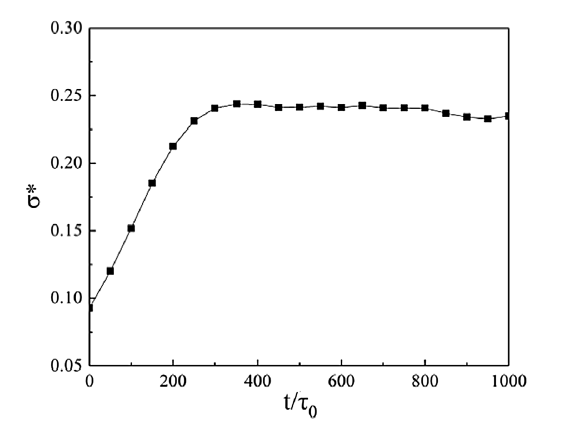
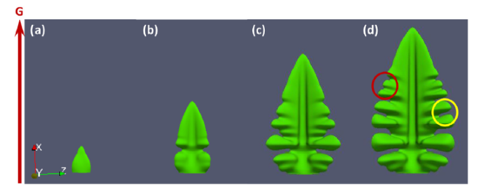
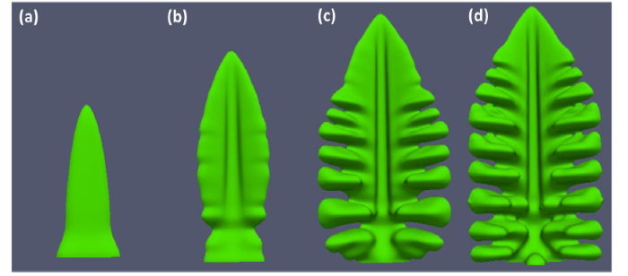
Unlike equiaxed dendrites, the directional solidification interface grows rapidly along the direction of heat flow under the action of temperature gradients. According to the microscopic solvability theory, the expression of the steady state coefficient of the dendrite tip is σ*=2DLd0/(R2V) [38]. Fig. 1 shows the change of the selection coefficient of the dendrite tip of Al-0.5% Zn alloy at G=20 K/mm and VP = 4 mm/s. At the early stage of dendrite growth, the value of RV is also unstable due to the growth rate of the dendrite tip and the radius of the dendrite tip, that is, σ* is constantly changing. As solidification progresses, grain growth stabilizes when t = 300τ0 and σ* tends to be stable. Fig. 2 shows the morphology of the directional solidification interface front of Al-0.5 wt% Zn alloy at G = 20 K/mm and VP = 4 mm/s. The direction of the temperature gradient is the same as the direction of the X-axis, so the heat dissipation rate of the dendrites in the X-axis direction is greater than that in the other directions, and the dendrites grow rapidly along the X-axis direction, generating a large number of secondary dendrites on both sides of the dendrites under the disturbing action. These secondary dendrites are perpendicular to the X-axis and have no advantage in terms of heat dissipation, so the length is short. This paper simulates the directional solidification of a single grain. Subject to multi-grain directional solidification, the distance between each grain is limited, which also limits the growth of secondary dendrites. From Fig. 2(d), the competitive growth and fusion phenomenon of secondary dendrites (such as the inner part of the red circle) can be observed, the first generated secondary dendrites are in contact with adjacent secondary dendrites during growth, so that the dendrites are combined to form coarser secondary dendrites. These secondary dendrites are asymmetrical to the Z-axis under the action of a temperature gradient, as shown by the yellow circle in Fig. 2(d), and the lower half of the secondary dendrites (in the direction of the reverse heat flow) are straight. The heat dissipation advantage of the upper part (smooth flow direction) in the X-axis direction makes it form an upward spherical protrusion, while the vertical heat flow direction grows sluggishly, thereby forming a "fine-high-pine-like" overall shape.
Fig. 1. Evolution of dendrite tip selection constant of Al-0.5%Zn alloy during directional solidification (G = 20 K/mm, VP = 4 mm/s).
Fig. 2. Morphology evolution of the liquid/solid interface frontier of Al-0.5%Zn alloy during directional solidification (G = 20 K/mm, Vp = 4 mm/s), (a) t = 50τ0, (b) t = 100τ0, (c) t = 200τ0, (d) t = 300τ0.
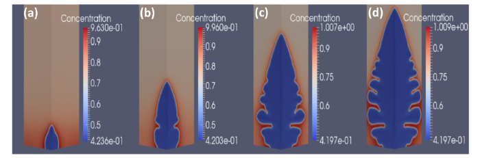
Fig. 3 shows the solute field changing of the liquid/solid interface frontier of Al-0.5%Zn alloy during directional solidification at G = 20 K/mm and VP = 4 mm/s. It can be seen that the redistribution of solute occurs during solidification and a large amount of solute is discharged to the solid/liquid interface front, distributed on both sides of the dendrite, and the gap between the grown secondary dendrite arms is filled with the solute-rich liquid. A large amount of solute is enriched in the dendrite roots, forming solute segregation, and the degree of segregation in the center of the dendrite is small, and the segregation away from the center and the dendrite root is more serious.
Fig. 3. Solute field changes of the liquid/solid interface frontier of Al-0.5%Zn alloy during directional solidification (G = 20 K/mm,Vp = 4 mm/s), (a) t = 50τ0, (b) t = 100τ0, (c) t = 200τ0, (d) t = 300τ0.
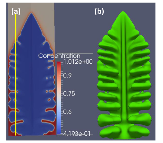
Fig. 4 shows the solute field and morphology distributions of the single grain liquid/solid interface frontier of Al-0.5%Zn alloy during directional solidification. It can be seen that below the tip of the grain, uniform secondary dendrites close to each other are formed. These secondary dendrite spacings are nearly uniform and the length is close to the same. They are closely arranged, and the solute in the gap and the root of the main branch is enriched in a large amount. Many multi-level pores can be found. Multi-level fusion phenomenon, resulting in multi-level segregation.
Fig. 4. (a) Solute field and (b) morphology distributions of the single grain liquid/solid interface frontier of Al-0.5%Zn alloy during directional solidification at t = 700τ0 (G = 20 K/mm, Vp = 4 mm/s).
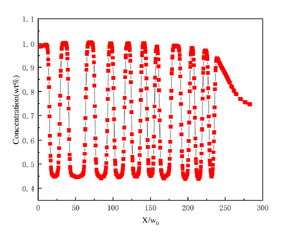
Fig. 5 shows the solute concentration change of the left of yellow line in Fig. 4 at X-axis direction. It can be seen from the curve that the solute concentration between the main dendrite and the secondary dendrites is relatively high, the secondary dendrites and the liquid phase rich in solute between them are uniformly distributed, and the width of the secondary dendrites and the gap between them are relatively average. The solute concentration gradually decreases near the tip of the dendrite.
Fig. 5. Solute concentration change of the left of yellow line in
Unidirectional heat flow control is an important part of directional solidification forming technology. For determining the alloy, the process parameters are the only means controlling the solidification structure, and the temperature gradient on the liquid phase side of the solid-liquid interface is the most critical.
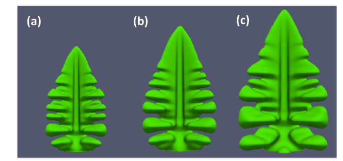
Fig. 6 shows the directional solidification dendrite morphology with different temperature gradient. It can be seen that as the temperature gradient increases, the growth rate of dendrites increases and the secondary dendrite becomes coarse. This is because the larger the temperature gradient, the faster the secondary dendrites grow along the heat flow side, which promotes the generation of protrusions along the direction of the temperature gradient, which are in contact with and merge with adjacent secondary dendrites to form a new coarse secondary dendrite. Therefore, when the temperature gradient is large, the secondary dendrites will tilt toward the heat flow direction and their fusion is increased, so the number of secondary dendrites is reduced and the secondary dendrites are coarser and the spacing becomes smaller.
Fig. 6. Directional solidification dendritic morphology with different temperature gradient at t = 300τ0 and Vp = 4 mm/s. (a) G = 20 K/mm; (b) G = 40 K/mm; (c) G = 100 K/mm.
In 1965, when Mullins and Sekerka [36] studied the stability change of the advancing interface during the unidirectional solidification of binary alloys, after considering the combined effects of solute capillary action and disturbance, the result which was contrary to the traditional undercooling theory of components was found: with the increases of growth rate, the morphology of the solid/liquid interface will undergo a transition from the flat interface-columnar crystal-dendrite-columnar crystal-banded structure-absolute stable flat interface, which is called MS theory [1].
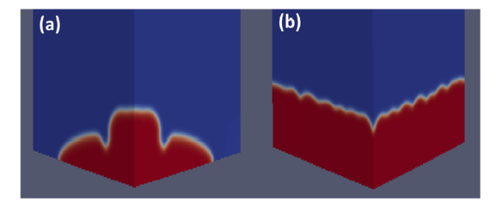
When the temperature gradient is increased to a certain extent, the solid-liquid interface will remain absolutely stable, no longer producing dendrites along the direction of heat flow, but will advance in a planar manner. As shown in Fig. 7, when the temperature gradient is 200 K/mm, dendrites having sharp tips are not formed on the interface, but a flat projection is formed. When the temperature gradient is increased to 2000 K/mm, the solid-liquid interface is completely stable and no protrusion is generated, the solid-liquid interface advances in a planar manner.
Fig. 7. Directional solidification dendrite with temperature gradients of (a) 200 K/mm and (b) 2000 K/mm, respectively, at t = 300τ0 and VP = 4 mm/s.
According to the MS theory [1], with the increase of growth rate, the solid-liquid interface morphology changes from flat interface-columnar to crystal-dendrite-columnar, and then to crystal-banded structure-absolute stable flat interface. Fig. 8 shows the dendrite morphologies at different interface pulling velocity at G = 20 K/mm, t = 400τ0. It can be seen that when the advancing velocity of the interface is small (VP = 1 mm/s, VP = 2 mm/s), the directional solidification interface grows in the form of cellular crystals and the solid/liquid interface is smooth on both sides, no secondary dendrites appear. As the advance velocity of the interface increases, the front of the solid-liquid interface changes from cellular crystals to dendrites, a large number of secondary dendrites begin to form and the amplitude increases gradually, the secondary dendrites grow along the direction of the heat flow, resulting in a decrease in the spacing, which is characterized by finer dendrites on the main branches. The increase of the interface advancing velocity also accelerates the growth of the secondary dendrites along the heat flow side, forming cubic dendrites perpendicular to the secondary dendrites direction and parallel to the main axis direction.
Fig. 8. Dendritic morphologies at different interface pulling velocities at G = 20 K/mm and t = 400τ0, (a) VP = 1 mm/s; (b) VP = 2 mm/s; (c) VP = 4 mm/s; (d) VP = 8 mm/s.
When the interface advancing velocity is further increased, the inclination of the secondary or tertiary dendrites is increased and the tertiary dendrites on the upper side of the secondary dendrite are more developed. Adjacent secondary dendrites contact and the spacing becomes smaller, and high-order dendrites are excited in a direction perpendicular to the temperature gradient.
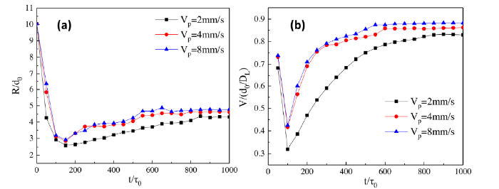
Fig. 9 shows the changing of tip radius and growth velocity of solid-liquid interface frontier at different pulling velocities. It is seen that as the advancing velocity increases, the growth rate of the dendrite tip which reaches a steady state slightly increases and the tip radius of the dendrite also increases after reaching steady state, but the increase is not obvious. It can be seen that the increase of the pulling speed will accelerate the growth of the interface front.
Fig. 9. Changes of tip radius (a) and growth velocity (b) of solid-liquid interface frontier at different pulling velocities.
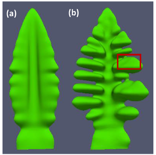
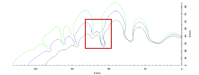
The above simulation process doesn’t add a thermal disturbance term and only depends on the interface disturbance; As shown in Fig.10 (a), when there is no thermal disturbance, the surface of the main dendrites is relatively smooth, only some tiny protrusions, no secondary dendrites are formed and the both sides of the dendrites are highly symmetrical. As shown in Fig.10 (b), when there is adding thermal disturbance, secondary dendrites grow on the main dendrites, tertiary dendrites appear on some secondary dendrites, and the secondary dendrites on both sides are extremely asymmetric. Since the position of secondary dendrite formation has a certain randomness, the spacing between some secondary dendrites will be small and the dendrites will fuse with each other to form coarse secondary dendrites. The competitive behavior between the secondary dendrites was observed at the box of Fig. 11: the formation of dendrites will inhibit the growth of dendrites and eventually eliminate or fuse these small dendrites. Thermal perturbation doesn’t affect the steady-state behavior of the dendrite tip, making the secondary dendrites more developed and more randomly distributed.
Fig. 10. Directional solidification dendrites under (a) unperturbed and (b) perturbed conditions.
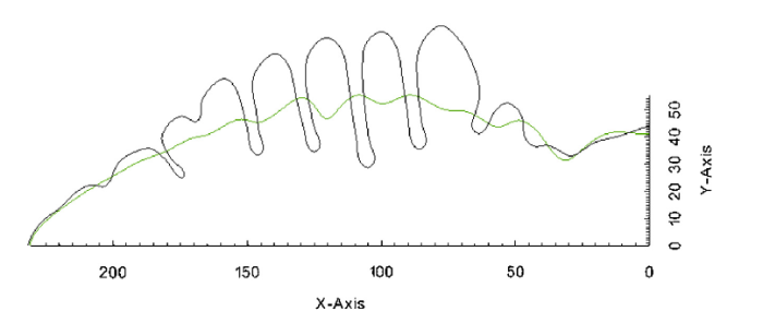
Fig. 11. Comparison of the outlines of the directional dendritic dendrite with perturbed, the black, blue and green contours correspond to 200τ0, 300τ0 and 400τ0, respectively.
Fig. 12 shows the comparison of the outline of the directional dendrite dendrite with unperturbed and perturbed. It can be seen that the length of the dendrite and the shape of the tip are consistent in the two case. This indicates that the thermal perturbation doesn’t affect the growth rate and tip radius of the dendrite tip during the directional solidification. The secondary dendrite amplitude of the heating disturbance is larger and the distance between the individual grains may increase during the growth of the multi-grain directional solidification dendrites.
Fig. 12. Comparison of the outlines of the directional dendrites with unperturbed and perturbed, the black contour is perturbed, and the green one is unperturbed.
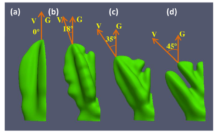
Fig. 13 shows the growth of dendrites under conditions of preferred growth orientation and temperature gradient in the directions of 0°, 18°, 35°, and 45°. Due to the four symmetry of the dendrites, the angle limit between the preferred growth direction of the grains and the direction of the temperature gradient is 45° [37]. As shown in Fig. 13, as the angle between the advance direction of the solid-liquid interface and the direction of heat flow increases, the asymmetric growth behavior of the secondary dendrite arm is strengthened, the secondary dendrite arm and the tertiary dendrite arm, which are in the same direction as the heat flow, grow faster and develop. The growth of the secondary dendrite arms opposite to the direction of the heat flow is suppressed, the length is small and there are no protrusions, as shown in Fig. 13(c).
Fig. 13. Dendrite growth morphology at the angle of (a) 0°, (b) 18°, (c) 35°, and (d) 45° between preferred growth direction and temperature gradient direction at Vp = 2 mm/s, G = 10 K/mm, and t=400τ0.
As the tilt angle increases, the length of the dendrites in the X-axis direction gradually decreases. This paper simulates a single grain, but can also infer the competitive relationship between the tilted dendrites and the adjacent normal dendrites (This paper refers to the same direction of pulling speed and temperature gradient as normal direction and normal dendrite). In the same time, the length of the tilted dendrites in the X-axis direction is necessarily smaller than the length of the normal dendrites. When the two are in contact, the normal dendrites tip is higher than the tilted dendrites tip, and the tilted dendrites tip growth is hindered by normal dendrites. After a period of time, the secondary dendrites of the normal dendrites also extend to the front of the tilted dendrites, further hindering its growth. Dendrites with smaller inclination angles may change in the direction of intense competition, and finally coincide with the direction of temperature gradient; while dendrites with larger inclination angles may be eliminated in competition with normal dendrites.
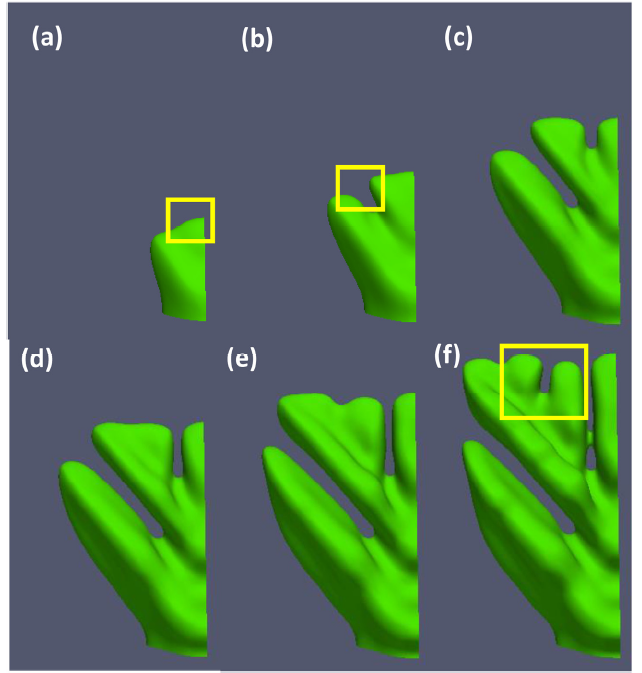
Fig. 13(d) is a dendrite with an angle of 45° between the advancing orientation of the interface front and the direction of the heat flow. Specially, the morphology of the solid-liquid interface is symmetrical about G (This paper takes half of the symmetry for comparison). The inner part of the yellow box in Fig. 14(a) is formed by the fusion of the secondary dendrites on the dendrites in the left and right directions. The direction is the same as G, the tip radius is gradually increased and the front end of the interface gradually becomes flat. When the tip radius exceeds the theoretical value of marginal stability, the dendrite tip is unstable. As Langer and Muller demonstrated in 1977, dendrites grow at the tip scale determined by the stability limit, called “Marginal Stability” [38]. Relatively speaking, the solute of dendrites with a large radius of curvature diffuses outward slowly, the solute is enriched at the tip. When the solute diffusion instability exceeds the interfacial energy stabilization, the tip cracking produces two small radius of curvature dendrites, namely the "liquid phase groove" or "tip splitting" phenomenon. At this time, the left protrusion starts to grow rapidly due to the small tip radius, and this dendrite belongs to the tertiary dendrite. The tertiary dendrites interacting with the primary dendrites grow in parallel and the tertiary dendrites inhibit the primary dendrites on the underside. As the solidification proceeds, the inhibition of the initial main dendrites by the upper dendrites increases, and the main dendrites are eventually eliminated.
Fig. 14. Dendrite growth process (VP = 2 mm/s, G = 10 K/mm) at 45° between preferred growth direction and temperature gradient direction, (a) t = 50τ0, (b) t = 200τ0, (c) t = 400τ0, (d) t = 600τ0, (e) t = 800τ0 and (f) t = 1000τ0.
As shown in Fig. 14(f), the advancing orientation of the tip position in the yellow box coincides with the direction of the temperature gradient, and has a growth advantage with respect to the other orientation of the front end. If the position is not suppressed by secondary dendrites of adjacent normal dendrites, they will grow rapidly under temperature gradients, eliminate other dendrites, become new major dendrites, and continue to grow along the temperature gradient. If the dendrites in the yellow box are suppressed by secondary dendrites of adjacent normal dendrites, this tilted dendrite will be eliminated. When the angle between dendrite orientation and temperature gradient is large, the initial main dendrites will be eliminated by its secondary dendrites or tertiary dendrites, and secondary or tertiary dendrites with orientation advantages may become new primary dendrites or may be eliminated by adjacent normal dendrites.
In this work, the phase field method is used to systematically study the synergistic regulation of solute redistribution, temperature gradient direction, interface advance speed, thermal disturbance, solid-liquid interface growth orientation and heat flow direction on solute segregation, growth orientation, secondary dendrites and multi-stage dendrites arm competition for various factors affecting the frontier advance morphology of solid-liquid interface during the directional solidification process. The conclusion is as follows:
(1) The dendrites at the front of the solid-liquid interface are symmetric about the main axis, but under the action of a single heat flow, the secondary dendrite arms grow severely asymmetric. The growth in the direction of the reverse heat flow is straight, and the semi-ellipsoidal protrusions is formed in the direction of the heat flow and the growth in the direction of the vertical heat flow is sluggish, forming a "fine-high-pine-like" overall morphology; Solute redistribution occurs during directional solidification, causing a multi-stage fusion phenomenon of multi-stage pores, thereby forming a multi-stage solute segregation.
(2) The larger the temperature gradient, the faster the secondary dendrites grow along the heat flow side, promoting the generation of protrusions along the temperature gradient. These protrusions contact and fuse with adjacent secondary dendrites to form a new coarse secondary dendrite, thereby tilting toward the heat flow while reducing the number of secondary dendrites; when the temperature gradient is increased to a certain extent, the solid-liquid interface will no longer produce dendrites along the direction of heat flow, but will advance forward in a stable flat interface.
(3) When the interface advancing speed is small, the interface grows with cellular crystals and no secondary dendrites appear. As the advance velocity increases, the front edge of the interface changes from cellular crystals to dendrites, and a large number of secondary dendrites are formed. At the same time, tertiary dendrites are gradually formed, and further contact or fusion is performed to form secondary or tertiary inclined dendrites. When the interface advance speed is further increased, the dendrite inclination is increased, the tertiary dendrites on the upper side of the secondary dendrite are more developed, and new secondary dendrites are excited in the direction perpendicular to the temperature gradient.
(4) When there is no thermal disturbance, secondary dendrites are not formed, the dendrites are smooth and the left and right sides are highly symmetrical; thermal disturbances don’t affect the steady state behavior of the dendrite tip.
(5) As the angle between the advance direction of the solid-liquid interface and the direction of heat flow increases, the asymmetric growth of the dendrites is strengthened, the dendrite growth in the direction of heat flow is accelerated and developed and the dendrite growth in the direction of reverse heat flow is suppressed. Dendrites with smaller tilt angles may change in the direction of competition, and eventually coincide with the direction of temperature gradient; dendrites with larger tilt angles may be eliminated in competition with normal dendrites. When the tip radius of the interface exceeds the theoretical value of the marginal stability, the dendrite tip crack to produces two dendrites of small curvature radius, namely the "liquid phase groove" or "tip splitting" phenomenon. At this time, the tertiary dendrites grow in parallel with the main dendrites, and the hindering effect on the underside main dendrites is strengthened and the main dendrites are finally eliminated.
This work was financially supported by the National Natural Science Foundation of China (NSFC) under grant Nos. 51774254, 51774253, U1610123, 51574207, 51574206, and the Science and Technology Major Project of Shanxi Province under grant No. MC2016-06.
The authors have declared that no competing interests exist.

 WeChat
/
| 〈 |
|
〉 |