Search for articles:
Qiaomu Liu , Shunzhou Huang, Aijie He
Corresponding authors:
Received: 2019-01-9
Revised: 2019-03-24
Accepted: 2019-03-28
Online: 2019-12-05
Copyright: 2019 Editorial board of Journal of Materials Science & Technology Copyright reserved, Editorial board of Journal of Materials Science & Technology
More
Abstract
Composite ceramics thermal barrier coatings (TBCs) are widely used in the aero-engines field due to their excellent thermal insulation, which improves the service life and durability of the inherent hot components. The most typical, successful and widely used TBCs material is yttria stabilized zirconia (YSZ). In this paper, fabrication methods, coating structures, materials, failure mechanism and major challenges of YSZ TBCs are introduced and reviewed. The research tendency is put forward as well. This review provides a good understanding of the YSZ TBCs and inspires researchers to discover versatile ideas to improve the TBCs systems.
Keywords:
The aero-engine is known as the "heart" of the aircraft, which can provide the driving force for the aircraft. In order to make the aircraft more dynamic and more stable, the aero-engine must have a greater thrust-weight ratio. Increasing the turbine inlet temperature (TIT) can significantly improve the efficiency and achieve the higher thrust-weight ratio of the aero-engine [1]. With the increase of the TIT, the hot components will suffer from the more serious test of severe service environments such as hot corrosion, high stress, and strong oxidation. The surface temperature of turbine blades will be much higher than the ultimate temperature of the most advanced blade alloy material, even with the high-efficiency gas film cooling technology [2,3]. In addition, improve the cooling effect by increasing the cooling gas flow, which leads to engine performance degradation and fuel waste. However, composite ceramic thermal barrier coatings (TBCs) are the only feasible way to reduce the working temperature of the alloyed blade surface and improve the thrust-weight ratio of the aero-engine. Therefore, TBCs have become one of the three key technologies of turbine blades for the advanced aero-engines [1,4].
TBCs are a kind of thermal protection technology that the ceramic materials with a high melting point and low thermal conductivity are deposited on the hot components to reduce their surface temperature [1,[5], [6], [7], [8]]. The concept of TBCs was firstly introduced by NASA Lewis research center to improve the high-temperature oxidation resistance and corrosion resistance performances of the turbine blades of rocket engines in the 1950s [9]. TBCs are the most complex coating system, which involves not only the coating material but also the structure and preparation process of the coating. The complexities of TBCs can seriously affect the achievement of the desired performance due to the inherent complex interplay with the substrate. Meanwhile, TBCs are highly sensitive to the deposition processing and compositions of the coating. In other words, their properties and structures are critically depended upon the deposition processing and compositions. With the development of science and technology, TBCs have made great progress. According to the literature [1,3], the surface temperature of the hot components can be reduced about 170 °C, the cooling air flow and the fuel consumption are observably reduced, and the blade service lifetime is prolonged several times after the TBCs application. Therefore, TBCs will have an important and wide application prospect in the aero-engine industries filed.
In recent decades, the TBCs materials and coating preparation, performance characterization and life prediction have been extensively and deeply investigated, providing the basis for TBCs application. This paper provides a summary of the recent developments in the TBCs, which involve the TBCs structure, preparation technologies, TBCs materials, the failure mechanisms, and future research directions. Salient developments and achievements are reviewed below.
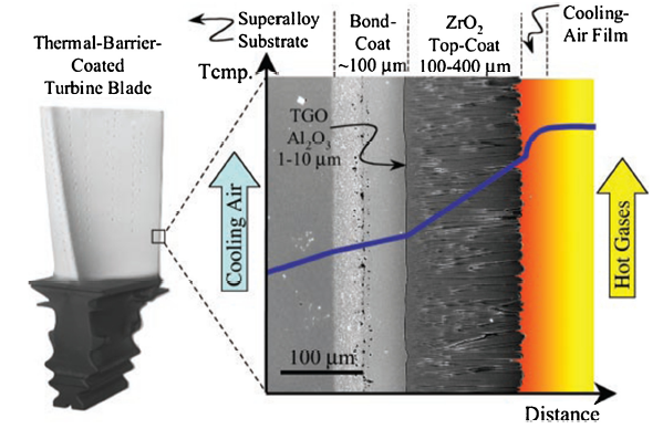
The TBCs systems include two-layer structure, gradient structure and multilayer structure. The most typically and widely used TBCs is yttria stabilized zirconia (YSZ)/MCrAlY (M = Ni, Co) two-layer structure, as shown in Fig. 1 [3]. The typical structure of two-layer TBCs is composed of a bond coat (BC) and a ceramic topcoat, as seen in Fig. 1. The ceramic topcoat with low thermal conductivity and a thickness of 100-400 μm can mainly provide excellent thermal insulation, strain tolerance, and thermal shock resistance for the hot components through reducing the heat transfer. The bond coat with a thickness of 40-200 μm would provide the oxidation resistance and corrosion resistance, and match the thermal properties and stress between the substrate and the ceramic coating. At the same time, a thin and dense thermal growth oxide layer (Thermally Grown Oxides, TGO) with α-Al2O3 as the main composition will be generated between the bond coat and the ceramic coat in the long use to prevent the further diffusion of oxygen and protect the alloy substrate. However, the failure of TBCs always occurs at the TGO/BC interface due to its intrinsic brittleness [10,11]. In addition, the interdiffusion behavior between the bond coat and the substrate will take place during the service process of TBCs, resulting in a secondary phase precipitated and the diffusion layer formed [12,13].
Fig. 1. A cross-sectional image of a TBC system on an aero-turbine blade [
Gradient structure for TBCs is continuous change of composition and/or structure to eliminate the interface between the ceramic coat and the bond coat by controlling the preparation process. Guo et al. fabricated the Al2O3-YSZ gradient TBCs by electron beam physical vapor deposition [14]. The results showed that Al2O3-YSZ gradient TBCs exhibited a better thermal shock resistance than YSZ/NiCoCrAl TBCs, and also revealed a relatively low oxidation rate under cyclic exposure due to the formation of a pre-deposited Al2O3film on the bond coat. The pure ceramic coat thickness is reduced, and the thermal stress in the coating is alleviated due to the introduction of the gradient layer structure so as to improve the thermal shock resistance and prolongs the service lifetime of the TBCs. But it is difficult to accurately control the gradient structure because of the complex gradient structure preparation process.
The multilayer structure TBCs system is developed to alleviate the thermal stress mismatch and improve the oxidation resistance and hot corrosion resistance of the coating. Each coat has its own specific function in the multilayer structure TBCs. The outer seal layer is mainly used to prevent the hot corrosion of SO3, SO2, V2O5 and other corrosive substances. The oxygen barrier layer can effectively reduce the internal diffusion of oxygen. But the thermodynamics of multilayer structure TBCs is more complex and the coating preparation is also relatively difficult, so multilayer structure TBCs is still in the basic research phase.
Up to now, various methods, such as plasma spraying (PS), electron beam physical vapor deposition (EB-PVD), plasma spray-physical vapor deposition (PS-PVD), high velocity oxy-fuel (HVOF), magnetron sputtering, arc evaporation, electrochemical deposition, and sol-gel, etc., have been developed to fabricate the TBCs [[15], [16], [17], [18], [19]]. Especially, PS, EB-PVD, and PS-PVD are more widely investigated and discussed.
The PS TBCs were first invented in the 1960s. In the process, the starting metallic and ceramic powders are injected into the high temperature plasma jet, and then can normally be heated to a fully molten and/or partially molten state, subsequently deposited on the substrate. The molten droplet will impact on the surface of the substrate due to its own high speed, spread out like a disk, and finally the layers of the discs will spread to form a coating. In recent decades, several PS methods, such as atmospheric plasma spraying (APS), low pressure plasma spraying (LPPS), and solution precursor plasma spraying (SPPS), vacuum plasma spraying (VPS) and protective atmosphere plasma spraying (PAPS), have been further developed for TBCs fabrication [[18], [19], [20], [21]].
The APS and LPPS are the two main methods for the deposition of TBCs. They have advantages such as low cost, rapid deposition rate, high efficiency, easily manageable, and so on. The TBCs deposited by APS or LPPS exhibit a characteristic sponge-like microstructure which appears to be a complex laminated structure containing a huge number of ubiquitous pseudo-random distributed pores and voids with various sizes and shapes. Generally, the porosity of APS TBCs is in the range of 3-20%, while the accepted porosity range for TBCs is 10-15% [3]. The intra-, inter-lamellar pores and network crack-like voids can effectively reduce the thermal conductivity, which makes the laminated PS coating quite suitable for TBCs applications. However, inter-lamellar pores, microcracks and microstructural defects which are parallel to the interface also increase the possibility of delamination and spallation. Moreover, it results in low elastic modulus and poor adhesion of the lamellae [22]. Therefore, this process is well suitable for the parts with large volume and weak mechanical properties needed, such as the combustion chambers, fuel vaporizers, and stator vanes.
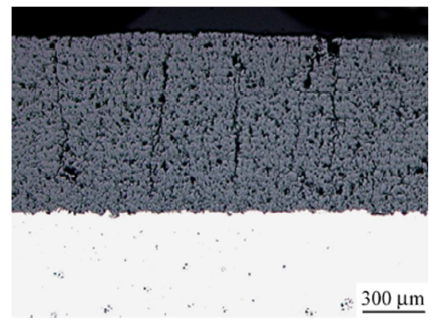
In recent years, even-distributed vertical cracks are successfully introduced into the APS stratified structure by adjusting the spraying process parameters after the exploration and improvement of the APS technology [23,24]. The vertical cracks greatly improve the stress-strain tolerance and thermal cycle life of TBCs, its typical microstructure is shown in Fig. 2 [23].
Fig. 2. The cross-sectional morphology of the PS TBCs with segmentation crack structure [
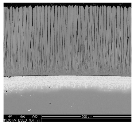
In the 1980s, the United States, Britain, Germany, and the former Soviet Union began using EB-PVD technology to fabricate TBCs. In the mid-1990s, the low cost EB-PVD equipment was invented by Ukraine Paton international electron beam center and popularized around the worldwide, setting off a new wave of development of EB-PVD TBCs. In the process, an electron gun gives off an electron beam in the vacuum chamber, thermal electrons are accelerated under high voltage. Further, the high-speed thermal electrons strike the metallic or ceramic target materials to melt and vaporize the target materials, and subsequently deposit on the substrate to form a coating [25]. The typical structure of EB-PVD YSZ TBCs is shown in Fig. 3 [26].
Fig. 3. The cross-sectional morphology of EB-PVD YSZ TBCs [
The EB-PVD TBCs exhibit excellent aerodynamic properties. They have better surface roughness than those of PS TBCs and do not block fine cooling holes [27]. The EB-PVD TBCs acquire a characteristic columnar microstructure within randomly distributed multi-scale porosity, and a very thin layer exists in the form of equiaxed grains near the interface between the bond coat and the ceramic coat. The columnar grains are separated by their inter-channels which are parallel to the direction of the heat conduction. The columnar grains inter-channels can improve the strain tolerance, thermal shock resistance of the TBCs system and relax their thermal expansion mismatch stresses [28]. However, EB-PVD TBCs result in higher thermal conductivity and lower thermal insulation than those of APS TBCs.
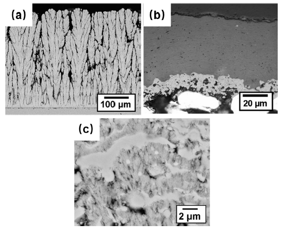
Plasma spray-physical vapor deposition (PS-PVD) technology is a new type of coating preparation method developed on the basis of physical vapor deposition and plasma spraying. In the process, the high energy plasma jet produced by a high power plasma spray gun with low working pressure. The high energy plasma jet can not only melt the spraying particles but also make them gasification, so as to realize the gas, liquid and solid multiphase composite deposits and the controlled microstructure [29,30]. The YSZ coatings with different structures were prepared by PS- PVD [31,32], as shown in Fig. 4 [32]. It is also worth noting that the high energy plasma jet can diffract into the shadow region of the complex geometry parts and the coating is deposited on its surface, so the process can breakthrough the technical bottleneck of the visual deposition.
Fig. 4. PS-PVD YSZ coatings with different microstructures (a) quasi-columnar coating, (b) lamellar coating, (c) hybrid coating [
The APS coating exhibits a lamellar structure and has good thermal insulation performance but poor bonding strength and poor thermal cycle life. The EB-PVD coating exhibits a columnar structure and has excellent thermal cycle life but poor heat-insulation performance. Compared with conventional PS and EB-PVD technologies, PS-PVD technology has the common advantages of PS and EB-PVD. In addition, PS-PVD technology has the advantages of fast deposition speed and low cost of PS technology, and uniformity and density of EB-PVD technology.
As aforementioned, the EB-PVD TBCs with the columnar structure exhibit stronger adhesive strength and longer thermal-cycling lifetime than those of PS TBCs with the laminated structure which exhibit the good resistance to oxidation, corrosion, and poor adhesive with the substrate. Although PS-PVD TBCs have many excellent properties, the study of PS-PVD TBCs is still in the primary stage and the basic theoretical problems related to the deposition process need to be systematically investigated. Therefore, the comparative analysis indicates that the EB-PVD and PS-PVD TBCs are used primarily for the harsh applications with a small volume such as turbine blades in aero-engines, while the APS TBCs are used suitably for the mild applications such as combustors and stator vanes in aero-engines. In general, the EB-PVD and PS-PVD TBCs are gradually becoming popular and will play a pivotal role in the future.
Two types of generated metallic bond coatings are modified aluminium or chromium compounds coating and MCrAlY coating (M = Ni, Co, Fe and/or their combinations) [3,33,34]. The well-known first-generation bond coat is platinum (Pt) modified aluminide diffusion coating, which is fabricated by electroplating Pt with 7-10 μm thickness, followed by aluminizing using chemical vapor deposition (CVD) or pack cementation. Noteworthy, Pt can improve the stabilization and adhesive strength of the coating by reducing the inter-diffusion between the coating and the matrix. However, Pt is expensive and does not have adequate strength at high temperatures. In addition, Zirconium (Zr), hafnium (Hf), lanthanum (La), ruthenium (Ru), and yttrium (Y) modified aluminide coating have also been investigated [[35], [36], [37]].
The second-generation bond coat is MCrAlY coating with a small amount of Y. The widely investigated MCrAlY coatings are NiCrAlY, CoCrAlY, and NiCoCrAlY coatings which can be easily fabricated by PS, HVOF, EB-PVD, or vacuum arc plating (VAP) [[38], [39], [40], [41]]. In the MCrAlY coating systems, Al and Cr contents are in the range of 8-18 and 16-24 wt.%, respectively [[42], [43], [44]]. The Y content is in the range of 0.3-1 wt.%. Al can form an Al2O3 film on the top of the bond coat to protect the underneath bond coat, which increases the oxidation resistance. Cr can form Cr2O3 and increases the hot corrosion resistance. Furthermore, Y can improve the adhesion of the TGO and thermal shock resistance. Moreover, the composition of MCrAlY coating system can be specifically adjusted by adding Ta, Nb, Re, Hf, Zr, and/or other components to improve the high temperature performance, prolong the lifetime, and match other specific requirements. With the increase of the TIT of the aero-engine, MCrAlY material has not been able to meet the needs, and new ultra-high temperature bond coat materials have become the focus of research.
Intermetallic compounds NiAl, which has a high melting point (1638 °C), low density (5.9 g/cm3), relatively high elastic modulus (240 GPa) and good oxidation resistance at 1200 °C, is one of promising ultra-high temperature candidate materials for metal bond coat [[45], [46], [47], [48]]. But the practical application of NiAl is limited by its brittleness, the weak adhesion strength between the oxidation film and the substrate under the high-temperature environment. In addition, the easy diffusion of Ni and Al atoms into the matrix also limit the practical application of NiAl. It is reported that the modification of NiAl by Pt, Ru, and active elements can overcome the above shortcomings [[49], [50], [51]]. For example, the active element Dy modified NiAl can effectively improve the cyclic oxidation performance and reduce the growth rate of the oxide film [45,46,49]. Additionally, the adhesion of oxidation film and the high-temperature oxidation resistance of the NiAl can be significantly improved by Pt modification [51].
With the increase in thrust-weight ratio, new generation aero-engines make use of single-crystal superalloys with a small amount of or even without carbon component to work under high TIT. For the single-crystal superalloy substrate, the diffusion of Al and Cr from bond coat to the substrate promotes the formation of harmful topologically closed packed (TCP) phases and a secondary reaction zone (SRZ) when singly aluminized or chromized coating are directly fabricated [49,52,53]. Therefore, carbon-doped layer, Pt-modified aluminized coating, or other diffusion barrier coatings should be fabricated before the fabrication of bond coating on the surface of substrates. Moreover, the Pt-doped aluminide is not prone to the SRZ effect because of its barrier for Al diffusion. Metal and ceramic composite bond coats were also produced by LPPS to further match the coefficient of thermal expansion (CTE) between the ceramic coat and the bond coat [54].
Ceramic materials for TBCs must have many desirable properties, such as high melting point, low thermal conductivity, phase stability in the operated temperature range, matched CTE, good adhesive strength, chemical inertness, low sintering rate, and so on [[1], [2], [3],5]. CTE and thermal conductivity are the most important properties for TBCs. A single ceramic material can hardly meet all the requirements for TBCs ceramic materials. The combination of two or more ceramic materials, such as Y2O3-stabilized HfO2, Y2O3/Gd2O3 stabilized ZrO2 (YSZ/GdSZ), may meet the requirements for TBCs ceramic materials.
Compared with other TBCs systems, 6-8 wt.% yttria stabilized zirconia is the most successful topcoat ceramic materials due to its relatively low density, low thermal conductivity attributed to its high concentration of point defects, ability of stress relaxation caused by compatible CTE, and strain tolerance [2,5,7]. So far, the superior successor of YSZ has not been developed yet. On the other hand, YSZ also has some disadvantages for TBCs applications such as limited operating temperature (<1200 °C), sensitivity to the hot corrosion, impressionable to environmental sediments, and accelerated TGO formation caused by the extremely high ionic oxygen diffusivity in the ZrO2-based ceramics [55,56]. Therefore, it is necessary to seek new stabilizer for zirconia and novel ceramic candidates to meet the demands of TBCs materials for higher TIT. Multiple oxide co-doped zirconia, A2B2O7-type pyrochlore and fluorite compounds (A = La, Gd, Sm; B = Zr, Ce), magnetoplumbite compounds (LaMgAl11O9 and LaTi2Al9O19), garnet-type compounds (Y3Al5O12), perovskites (SrZrO3, BaLa2Ti3O10) and other new oxide ceramics can be used as candidate materials for higher temperature TBCs ceramic materials [2,5,[57], [58], [59], [60], [61], [62]].
Among these candidate materials, multiple oxide co-doped zirconia, La2Zr2O7 and Gd2Zr2O7 are considered the most promising TBCs materials. Multiple rare earth oxides co-doped zirconia can further reduce its thermal conductivity and improve the high-temperature phase stability of t′ phase (metastable tetragonal phase), which have been verified instead of YSZ through first principles and experiments [2,7,57]. Thermal conductivity of 3.7 Sc2O3-3.7 Gd2O3-92.6 ZrO2 (mol %) is 1.47-1.58 W m-1 K-1 from 20 to 1400 °C, which is about 40% lower than that of 4.5 YSZ (2.35-2.65 W m-1 K-1). Sc2O3-Gd2O3 co-doped ZrO2 has still good phase stability from room temperature to 1400 °C [63]. In addition, ZrO2-Ta2O3-Y2O3 not only had low thermal conductivity and excellent phase stability but also improved the V2O5 and SO2 hot corrosion resistance [64,65]. Furthermore, both La2Zr2O7 and Gd2Zr2O7 have low thermal conductivity, high melting point, low sintering rate, and high-temperature phase stability. However, thermal cycle life of La2Zr2O7 and Gd2Zr2O7 TBCs are relatively short due to their low CTE, poor fracture toughness, and high-temperature chemical compatibility with Al2O3 [2,5,66]. The thermal cycle performance of La2Zr2O7/YSZ and Gd2Zr2O7/YSZ double ceramic layer TBCs through structural optimization design is very excellent at high temperatures [67,68]. Different materials in combination and multi-layered structure ceramics topcoat may be the promising choices.
Thermal cycle lifetime and thermal shock lifetime are the most important properties of TBCs, which are always used to characterize the stability and durability of the TBCs. The service environments of TBCs are extremely complex, including high temperature oxidation, hot corrosion, wear and impact, environmental sediments (CaO-MgO-Al2O3-SiO2, V2O5, and SO2) deposition, and so on [1,69]. The service life of TBCs is affected by these service environmental factors, coating structure, and properties of the coat materials, which made the complicated failure modes of the TBCs. As a result, the accurate prediction of the service life of TBCs has become a research focus in the field of TBCs, and the failure mechanism of TBCs is especially important.
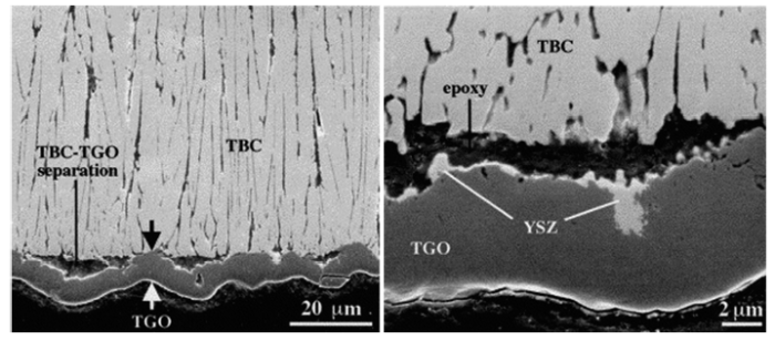
YSZ, multiple rare earth co-doping YSZ such as A2B2O7-type rare earth zirconates contain many oxygen vacancies. When these materials serve as TBCs at high temperature, TGO are generated. Although the TGO film can effectively inhibit the further oxidation of the bond coat, they cause thermal stress which can lead to crack initiation, extension and therefore failure of the TBCs. Fig. 5 shows the failure of the TBCs due to the cracking of the TGO film [70].
Fig. 5. The coating failure caused by the cracking of the TGO film [
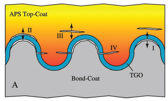
Because the TGO film is between the ceramic coat and the bond coat, the formation of the TGO film is subjected to a great plane pressure stress. Therefore, TGO tends to expand in the plane to release the lattice distortion energy. When it constrained by the adjacent coatings, the TGO film is inclined to deform in the form of a vertical interface to obtain a larger surface area, and some wrinkles are generated. The bond coat also synergistically deforms because the TGO film adheres to the bond coat. The distorted TGO film will exert large tensile stress to the adjacent coatings, resulting in the initiation and expansion of the microcracks in the coating, as shown in Fig. 6 [71]. When a certain number of adjacent cracks connect to each other, the coating appears to flake off. Ni, Co, and Cr elements may diffuse outwards with the consumption of Al element for a long time at high temperature, and the spinel phase composed of Ni, Co, Cr, Al will be generated between the TGO film and ceramic coat [69,72]. The brittle fracture of the spinel phase is easy to occur under stress because of the brittleness of the spinel phase, resulting in delaminations of the coatings.
Fig. 6. A schematic illustration showing the cracking mechanism in the APS TBCs [
Phase transformations from the t′ phase to tetragonal and cubic (t + c) and then to monoclinic (m) phase would occur when the temperature of service environment is above 1200 °C [1,2,5,69]. At the same time, the sintering phenomenon would occur along with volume expansion and the formation of stress concentration. The decomposition of t′ phase under high temperature will adversely affect the service life of the TBCs.
In addition, the surface temperature of the ceramic coat has been improved with the increase of TIT. The ceramic coat tends to sintering under the high working temperature, resulting in the increase of its thermal conductivity. Consequently, the external high temperature gas would damage the super alloys due to the weak heat insulating property of the TBCs.
Another failure mode is the environment sediments failure. The TIT significantly rises with the increase of the thrust-weight ratio, which would bring about some harsh requirements for new materials. Especially, one failure mode caused by the environment sediments on the TBCs surface is becoming the focus of the TBCs field. These environment sediments mainly include dust, sand, volcanic ash, and runway debris, and their composition are calcium oxide, magnesium oxide, aluminum oxide, silicon dioxide (CMAS) and trace vanadium, sulfur, sodium, iron elements [[73], [74], [75]]. When the surface temperature exceeds the melting point of the environment sediments, these molten deposits infiltrate into the coatings through the open pores and interconnected cracks. The stabilizer of the zirconia dissolves in the melts, leading to the phase transformation with volume change, thermophysical and mechanical properties degradation of the TBCs, eventually accelerating the failure [[75], [76], [77]].
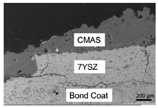
The failure of TBCs is indeed complex. Fig. 7 shows the failure of a real blade caused by the CMAS after high temperature service [78]. It can be observed from Fig. 7 that after reaction with CMAS YSZ coating crack through thickness and then parallel propagated horizontally at the YSZ/bond coat interface. When the surface temperature of the blade is higher than the CMAS melting point, CMAS is molten and can easily penetrate into the YSZ coating.
Fig. 7. Failed blade caused by the CMAS [
On the other hand, the YSZ ceramic coating is the fast ion conductor of oxygen at high temperature. When the oxygen enters into the YSZ coating and diffuses into the bond coat interface, the bond coat is oxidized to generate a black continuous Al2O3 film, namely the TGO film. The growth stress of the Al2O3 film and the thermal stress can lead to the cracking and peeling of the TGO film, which are harmful to the life of TBCs.
What is more, a series of non-destructive evaluation (NDE) methods of the detection, evaluation, and prediction have been developed to improve the integrity and performance of the TBCs toward reliable application on the aero-engine. The first applied qualitative and quantitative evaluation method is acoustic emission (AE) [79]. Besides AE, infrared thermography (IR) was developed to detect and evaluate the delamination and degradation of the TBCs [80]. Moreover, new NDE methods such as electrochemical impedance spectroscopy (EIS), photo-stimulated luminescence spectroscopy (PSLS) have been invented to detect and evaluate the formation and failure of TGO film in the TBCs [[81], [82], [83], [84]]. Undeniably, more significant explorations are demanded toward more convenient and reliable nondestructive testing methods to understand their failure, build the accurate performance models and predict the service lifetime of the TBCs.
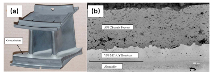
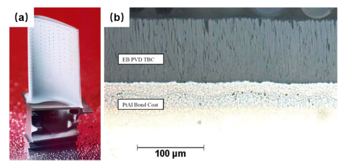
The applications of TBCs in the aero-engine have dramatically increased in the past decade. They are widely used on the hot stator or rotor components such as combustion chambers, fuel vaporizers, vanes and blades with the objective of extending the components service life, increasing the aero-engine durability, and reducing the operating costs (Table 1). Thus, various TBCs have been successfully applied on the hot stator or rotor components of different aero-engines in the General Electric (GE) and Pratt & Whitney Group (PW) in the USA [85]. Fig. 8 shows the macro- and micro-morphology of the VPS MCrAlY + APS YSZ TBCs on the outer platform of the high-pressure turbine (HPT) 2nd vane [85]. Fig. 9 exhibits the macro- and micro-morphology of the PtAl + EB-PVD YSZ TBCs on the HPT 1st blade [85]. The overhaul lifetime is in the range of 10,000~20000 h, corresponding to 2000-4000 cycles.
Table 1 Applications of TBCs on commercial aero-engine parts [
| Bond coat | Topcoat | Example GE | Example PW |
|---|---|---|---|
| VPS MCrAlY | APS YSZ | CF6-50 Vane 2 | V2500 Vane 1 |
| APS MCrAlY (aluminized) | APS YSZ | CF6-80 Vane 2 | not applied |
| aluminized | EB-PVD YSZ | CFM56-7 Vane 1 | not applied |
| Pt-Al | EB-PVD YSZ | CF6-80 Blade 1 | not applied |
| EB-PVD MCrAlY | EB-PVD YSZ | not applied | PW2000 Blade1 |
Fig. 8. (a) HPT stage 2nd vane with TBCs and (b) microstructure of the TBCs [
Fig. 9. (a) HPT stage 1st blade with TBCs and (b) microstructure of the TBCs [
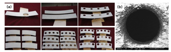
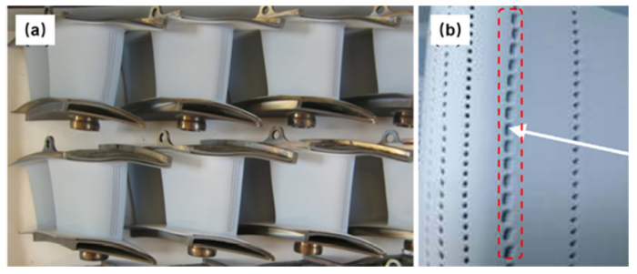
In China, the TBCs have been widely investigated in the past decade. Fig. 10(a) shows the macro-morphology of the HVOF MCrAlY + APS YSZ TBCs on the combustor tiles with a large number of cooling holes. Fig. 10(b) clearly exhibits the edge morphology of the as-coated cooling hole. Fig. 11(a) shows the macro-morphology of the VAP MCrAlY + EB-PVD YSZ TBCs on the HPT vanes with a large number of cooling holes with different diameters and incline angles. Fig. 11(b) shows the distinct shrinkage and the change in the diameter of the as-coated cooling holes, in particular, for the abnormity and incline cooling holes. Therefore, the researches related to the blocking of the cooling holes during the TBCs fabrication and the corresponding strategies are still being carried out. The adjustment of the TBCs process routing followed drilling the as-coated cooling holes is considered as one of the attractive methods. In addition, ultrafast laser etching and laser microjet methods also have been attempted to drill the coated turbine vanes and blades.
Fig. 10. (a) TBCs coated on the combustor tile and (b) the edge morphology of the cooling hole with TBCs.
Fig. 11. (a) HPT vanes with TBCs and (b) morphology of the cooling holes with TBCs.
The complexity and diversity of the TBCs systems make their investigations a time-consuming task. At present, the premature failure of the TBCs impedes their comprehensive applications and superior potentials. Furthermore, traditional TBCs materials are not suitable for the requirements of the next generation aero-engines with ultra-high TIT. Therefore, considerable efforts should be devoted to obtaining new candidate materials which are reliable and durable for the TBCs systems. Compared with the traditional TBCs, new candidate materials with microstructure design such as functionally gradient material TBCs, high segmentation crack density TBCs and nano-structured TBCs are expected to have extraordinary properties with the potential capability of working at higher temperatures. It has been found that the thermal conductivity drastically reduces for the nano-size materials. However, one of the biggest challenges is to retain the pre-existing nanostructure.
Besides experiments, complementary atomic-level simulations should be further investigated to guide the experiments, such as the critical stress-strain field. New types of NDE methods for evaluation and prediction of the TBCs should be cultivated and developed to improve the TBCs systems, such as qualitative and quantitative online detection of the evolution of microstructure and damage. The full potential of the advanced TBCs should be systematically explored to meet the requirements of the next generation aero-engines.

 WeChat
/
| 〈 |
|
〉 |