Search for articles:
Bo Zhou, Manling Sui
Corresponding authors:
Received: 2019-05-8
Revised: 2019-05-15
Accepted: 2019-05-20
Online: 2019-10-05
Copyright: 2019 Editorial board of Journal of Materials Science & Technology Copyright reserved, Editorial board of Journal of Materials Science & Technology
More
Abstract
{10$\bar{1}$1} compression twins with high density stacking faults were studied at atomic scale using Cs-correction transmission electron microscopy. On one side of the {10$\bar{1}$1} twin boundary, there were many steps arranged alternately with the coherent twin boundaries. Most of the steps were linked with stacking faults inside twins. Burgers vector of twinning dislocations and the mismatch strain at steps were characterized. Due to the compressive mismatch strain at steps, the high density stacking faults inside twins were formed at twin tips during twinning process. The localized strain at the steps would be related to the crack nucleation in magnesium alloys.
Keywords:
Magnesium and its alloys, as the lightest commercial structural metal materials, have been used in aerospace and automotive industries [[1], [2], [3]]. Due to their hexagonal close-packed (HCP) structure, there are no sufficient slip systems to meet Von Mises criteria [4]. Deformation twinning (including tension and compression twins) plays a significant role in mediating the strain along c-axis in magnesium alloys. Different from the {10$\bar{1}$2} tension twins that initiated at fairly low critical resolved shear stress (CRSS) and were frequently observed, the {10$\bar{1}$1} compression twins were only found under high stress during plastic deformation [[5], [6], [7], [8]]. It is on account of the non-close-packed of pyramidal plane {10$\bar{1}$1}, and interfacial defects (such as steps, dislocations, disconnections) will be generated at the twin boundaries (TBs) to accomplish the twinning process [9,10]. Also, the {10$\bar{1}$1} twin boundaries can convert slip dislocations into disconnections which tend to pile-up and relax via facet nucleation [11]. The interfacial structure of {10$\bar{1}$1} twins has been widely investigated. Serra et al. proposed a topological theory to describe the TB defects, finding that the heights of interfacial steps were mainly 2 and 4 atomic layers [12,13]. By molecular dynamic simulations, Li et al. [14] and Wang et al. [15] speculated that the 2-layer step was probably a more active one in {10$\bar{1}$1} twins. On the contrary, by combination of computer simulations and high resolution transmission electron microscopy (HRTEM), Wang et al. discovered that the twinning interface was a flat atomic plane without steps [16]. Recently, Zhu et al. reported various steps with Gd segregation at the {10$\bar{1}$1} twin boundaries in Mg-Gd alloys using atomic-resolution high-angle annular dark-field scanning transmission electron microscopy, including the finding of 7-layer step for the first time in hexagonal systems [17]. In addition, there are a lot of basal stacking faults (SFs) inside {10$\bar{1}$1} twins, which is another essential characteristic of {10$\bar{1}$1} twins and has attracted considerable attention in recent years [[18], [19], [20], [21], [22]]. The normal basal SFs, as typical planar defects in HCP metals, were divided into three types by virtue of different partial dislocations, i.e. intrinsic faults produced either by Frank partial dislocations (I1) or by Shockley partial dislocations (I2), and extrinsic fault produced by Frank partial dislocations (E) [22]. It has been found that a high density of SFs formed in matrix essentially leads to the production of magnesium alloys with high mechanical performance [23]. However, basal SFs discovered inside {10$\bar{1}$1} twins were recognized as anomalous SFs, which is referred to as partial stacking fault (PSF) to distinguish from normal SFs (I1, I2 and E types). Recently, some simulation results showed that PSFs in {10$\bar{1}$1} twins were formed by large atomic shuffles (∼0.16 nm) rather than dislocations involved, which is similar to the anomalous SFs in {10$\bar{1}$2} twins [24,25]. Even so, it is still lack of experimental investigations on high density SFs in {10$\bar{1}$1} twins, especially at atomic scales. The formation mechanisms of high density SFs inside twins are not well understood yet.
In the present work, a series of HRTEM observations on {10$\bar{1}$1} twins together with a high density of internal SFs were carefully performed to identify the atomic structural characteristics of TBs and SFs. It was found that the coherent twin boundaries (CTBs) and steps alternately arranged at TBs, and the formation of high density SFs was closely associated with the steps. Moreover, we proposed a formation mechanism associated with high density SFs inside {10$\bar{1}$1} twins that the mismatch between (0001)M (basal plane of matrix) and (10$\bar{11}$)T (pyramidal plane of twin) causes the compressive strain inside the twins, which is partially applied on (0001)T plane to active the formation of PSFs during twinning deformation. In addition, Burgers vector of twinning dislocation (TD) and strain state of TBs were characterized. Our results could greatly promote the understanding of the formation of high density SFs inside {10$\bar{1}$1} twins.
As-extruded magnesium alloy AZ31 (Mg-3%Al-0.7%Zn-0.3%Mn, wt%) sheets were used in the present study. Specimens were cut from the as-extruded sheet and annealed at 648 K for 12 h for complete recrystallization. Then specimens were rolled 10% at room temperature with a strain rate of about 10-3 s-1. TEM samples were cut along the rolling direction (RD), and then thinned by twin-jet electropolishing in a solution of 10% nitric acid, 30% glycerol, and 60% methanol at 253 K. Finally, ion milling (Gatan PIPSⅡ695) was used with low angle and low voltage at 243 K to remove surface contamination and oxide layers. Microstructure characterization was performed in an FEI Titan environmental TEM equipped with a Cs image-corrector operating at 300 kV with a point resolution of 0.68 Å.
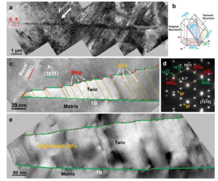
When c-axis of magnesium crystal is placed in compression, one of the deformation modes appears that basal planes rotate around the < 1$\bar{2}$10 > zone axis by 56.3° to form a {10$\bar{1}$1} twin. Typical cross-sectional morphology of the {10$\bar{1}$1} twins is a slender band shape, as shown in Fig. 1(a). The schematic twin relationship between the matrix and the twin is shown in Fig. 1(b). Fig. 1(c) and (e) show the zooming observations on the front part of the slender band, respectively corresponding to the dashed red frames in Fig. 1(a). Interestingly, the lower TB is almost flat, while the upper TB is irregular, consisting of many steps and flat segments. The flat TBs are parallel to the ({10$\bar{1}$1}) plane, while these inclined planes at each steps are approximately parallel to the (0001)M plane or the ({10$\bar{11}$})T plane. As shown in Fig. 1(d), the selected area electron diffraction (SAED) pattern taken at the interface between the matrix and the twin along <1$\bar{2}$10> zone axis presents a perfect mirror relationship with respect to the ({10$\bar{1}$1}) plane, i.e. a perfect {10$\bar{1}$1} twin relationship, in which the (0001)M plane and the ({10$\bar{11}$})T plane are not parallel to each other and have a 5.7° misorientation. Additionally, the high density SFs are in full of the whole twin and almost all the SFs cut through the twin lamella, as indicated by the dashed yellow lines in Fig. 1(c). Moreover, the diffraction streaks between the twin diffraction points (marked by yellow arrows in Fig. 1(d)) confirm the existence of the SFs on the (0001)T plane. It should be noting that most of the SFs exactly connected to the steps at the upper TB with one end and terminated at the lower TB, meanwhile there were almost no SFs in matrix in such a cold rolled sample.
Fig. 1. (a) TEM micrograph of a {10$\bar{1}$1} twin. (b) Schematic illustration of {10$\bar{1}$1} twin in a HCP unit cell. (c) Enlarged micrograph of the twin tip marked in (a). (d) SAED pattern corresponding to the {10$\bar{1}$1} twin along [$\bar{1}$2$\bar{1}$0] zone axis, yellow arrows indicate the SFs on (0001)T plane and (e) enlarged micrograph of the front part of the twin marked in (a). The green, red, and yellow lines represent the CTBs, steps and SFs, respectively.
Each segment of the {10$\bar{1}$1} twin lamella was studied by HRTEM, such as the HRTEM images taken in <1 $\bar{2}$ 10> zone axis in Fig. 2(a) and (b). From the HRTEM images, steps with different heights were measured and the statistical results of the step height are distributed in four, eight, ten, and fourteen layers of the {10$\bar{1}$1} planes. In particular, all the steps in our observations are multiples of two-layers, which is in agreement with the simulation results [14,15] but different from the observations in Mg-Gd alloys [17]. In addition to the step heights, we can confirm that, based on HRTEM observations, the inclined planes at all steps were located in between the two crystallographic planes, either closely parallel to the (0001)M plane or closely parallel to the ({10$\bar{11}$})T plane, which is related to whether the steps linked with the SFs.
Fig. 2. (a, b) HRTEM images of {10$\bar{1}$1} twin tip. (c, d) Enlarged HRTEM images of Step A and Step B, respectively. The dashed yellow lines represent the boundaries and the white arrow shows the SF in the twin. The insets of atomic planes schematically show the stacking sequence of the close-packed planes, in which the yellow, blue, and green balls represent the layer-A, layer-B, and layer-C, respectively. The red vector circuits are drawn surrounding Step A and Step B, and the direction vector of each circuit segment along the [1$\bar{2}$10] projection is accordingly listed the built-in tables, in which Λ= $ (2/3)^ \frac{1}{2}$c/a, P is the transformation matrix from the coordinate frame of the twin (marked by a subscript T) to that of the matrix (marked by a subscript M). (e, f) εyy strain maps of Step A and Step B. (g) Strain distribution curves of the lines 1-3 marked in (e) and (f).
In order to analyze the detailed microstructure of the steps linked with or without the SFs, two different 8-layer steps were selected and marked as Steps A and B by the dashed red frames in Fig. 2(a) and (b), respectively. Fig. 2(c) is the high magnification HRTEM image of Step A showing the interface between the matrix and the {10$\bar{1}$1} twin clearly, in which the 8-layer step linked with the flat CBTs at both ends. The CBT planes are coincided perfectly with the {10$\bar{1}$1} plane, showing a mirror-symmetric lattice relationship between the matrix and the twin. However, at the step, the interface of the matrix and the twin is approximately parallel to the ({10$\bar{11}$})T plane.
The interface disconnection with a step in the twinning plane was considered as a twinning dislocation [26]. Since the traditional Burgers circuit cannot be applied to calculate the atomic disarrangement at interfacial defects, herein we used a dichromatic diagram method [27] to draw Burgers circuits around the steps on twinning boundary and further to quantify the Burgers vector of TDs by the method of Pond [12]. As shown in Fig. 2(c), a closed circuit SABCDEF was constructed around Step A, and the direction vector of each circuit segment along the [1$\bar{2}$10] projection was listed in the built-in table. We calculated the Burgers vector of TD of this 8-layer Step A and achieved that the b8 twinning dislocation is about $\frac{1}{4}$[$\bar{1}$012], which is equal to four times of the 2-layer TDs [15]. Fig. 2(d) is a high magnification HRTEM image of Step B (another 8-layer step), which shows the interface at the step is approximately parallel to the (0001)M plane. In addition, Step B is just connected to a SF in the twin, as indicated by a white arrow. Thus, the atomic plane stacking sequence of ···ABABABAB··· is changed into ···ABABACAC···, as shown by the insets of atomic planes in Fig. 2(d). Similarly, a closed circuit SABCDEJKF was constructed surrounding Step B and the corresponding segments of the circuit were listed in the lower built-in table. The Burgers vector of the TD of the 8-layer Step B with a SF was calculated as $\frac{1}{4}$[$\bar{1}$012] + $\frac{1}{5}$[$\bar{1}$010.56] in the coordinate frame of the matrix. Obviously, the difference between Step A and Step B is whether the SF exists, and the Burgers vector of the SF is $\frac{1}{6}$[20$\bar{2}$3] in the coordinate frame of the twin, showing a consistency with the reported PSFs in twins [22].
Comparing with Step A and Step B, except for the difference in the Burgers vector with or without the SF component, there is another obvious difference in the image contrast at the steps (see Fig. 2(a)-(d)), which implies that the local strains were different. To analyze the strain of the two different steps, a geometric phase analysis (GPA) [28] was carried out by using a plug-in GPA software for the image-processing package in Digital Micrograph. We defined the x-axis being parallel to the step and the y-axis being parallel to the CTB. The εyy strain maps of Steps A and B are shown in Fig. 2(e) and (f) respectively, and the corresponding integral results of strain distribution along the lines 1-3 are shown in Fig. 2(g). It is evident that the strain gradient of either Line 1 across Step A or Line 2 across the lower left part of Step B is relatively uniform. However, the upper right part of Step B shows a great strain gradient in Line 3, indicating a significant localized strain. Apparently, the large localized compressive strain still remained at the upper right part of Step B, but the formation of the SF partially released the strain at the lower left part of Step B. In fact, based on our intensive HRTEM observations, most of the steps are connected to the SFs. In other words, the high density SFs inside the twins are activated to accommodate the huge localized strain at the steps. Thus, it is reasonable to deduce that the significant local strain concentrated at the steps led to the formation of SFs, resulting in high density SFs inside the {10$\bar{1}$1} twin lamella.
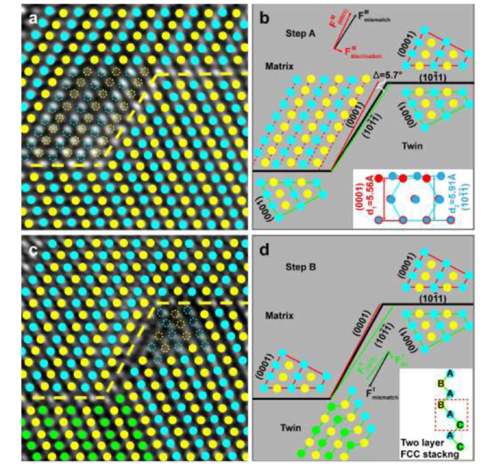
Fig. 3 shows the analysis on the local strain induced atomic accommodation at these two steps with or without the SF on the atomic scale. Based on the atomic location identification of the HRTEM images (Fig. 3(a) and (c)), the inclined facet for Step A is nearly parallel to the ({10$\bar{11}$})T plane (Fig. 3(b)), while that for Step B is close to the (0001)M plane (Fig. 3(d)). Based on the SAED pattern in Fig. 1(d), the orientation relationship between (0001)M plane and ({10$\bar{11}$})T plane has an angle difference about 5.7°, as indicated by the red and green lines nearby the steps in Fig. 3(b) and (d). Although the atomic arrangement and lattice spacing are different for the (0001)M and ({10$\bar{11}$})T planes (see the inset in Fig. 3(b)), the two planes would match well at the step interface by locally atomic adjustment during twinning deformation. Then, the (0001)M plane would be subjected to a tensile strain up to 5.9% in the case of Step A (Fig. 3(b)), or the ({10$\bar{11}$})T plane would be subjected to a compressive strain up to 6.3% in the case of Step B (Fig. 3(d)). Because the facet of Step A is approximately parallel to ({10$\bar{11}$})T, a tensile strain exists within the matrix to accommodate the misorientation angle, resulting in a deviation of (0001)M plane from the initial position (see the dashed circles in Fig. 3(a)). Therefore, this tensile strain leads to lattice distortion, and then generates a disclination in matrix to cause the rotation of (0001)M plane (Fig. 3(b)). However, due to the facet of Step B is approximately parallel to (0001)M, a compressive strain presents within the twin, leading to lattice distortion in twin (Fig. 3(c)). In addition, the basal plane is the close-packed plane in magnesium and the basal SFs is easily activated during deformation. Therefore, the mismatch strain was partially applied on (0001)T plane to active the formation of the PSFs during twinning deformation. A two-layer FCC stacking (···BAC···) generates inside the twin [22,29], as the inset shown in Fig. 3(d). Additionally, we also observed a mass of SFs at different steps inside the twins and found that all of them have the same stacking sequences.
Fig. 3. (a, b) The atomic marked HRTEM image and corresponding simulation diagram of Step A. The dashed circles and dashed red lines represent the ideal position of the atoms and the (0001)M planes, respectively. The inset shows the difference of the atomic arrangement and lattice spacing in the (0001)M and ({10$\bar{11}$})T planes. (c, d) The atomic marked HRTEM image and corresponding simulation diagram of Step B. The yellow, blue, and green balls represent the atoms on layer A, B, and C, respectively. The inset shows the two-layer FCC stacking sequence.
The formation of the PSFs inside the twins can greatly release the mismatch strain at the steps. However, the similar mismatch strain applied on the matrix does not lead to the formation of the basal SFs in matrix, even though the CRSS of (0001) plane is relatively low. It confirms that the formation of the high density SFs in {10$\bar{1}$1} twins are closely related to the twinning process at the steps during deformation, which is the typical PSFs companied by twinning [22] rather than the ordinary SFs like I1, I2, and E [19] formed by Frank or Shockley partial dislocations. Based on the HRTEM and GPA results, there is a close relationship between the PSFs and the steps due to the significantly mismatch stain. In addition, it is reasonable to link these steps with considerable local stains to the reported microcracks situated on the matrix/twin interface in AZ31 magnesium alloy [6].
To sum up the above analysis, the formation process of high density PSFs inside {10$\bar{1}$1} twins can be illustrated as in Fig. 4. When the external force is applied to the samples, the {10$\bar{1}$1} deformation twins begin to nucleate, which consists of a large number of steps. All the steps, including different layer heights, have the step facets localized between the (0001)M and ({10$\bar{11}$})T planes. Due to the mismatch strain at the step facets, the formation of the PSFs in twins would be actived during twinning shear at most of the steps, as shown in Fig. 4(a). With the slippage of TDs, the twins grew up and got thickening, and the PSFs that produced in the previous stage anchored at these steps and crossed the whole twin, as shown in Fig. 4(b). Some HRTEM images of the PSFs terminated at the bottom TBs of the {10$\bar{1}$1} twins are shown in Fig. 4(c) and (d). The PSFs generated from a high density of steps at the twin nucleation stage and grew with the thickening of the twins, resulting in the phenomenon of high density PSFs inside the {10$\bar{1}$1} twins.
Fig. 4. (a, b) Schematic illustration of the high density SFs expanding with the {10$\bar{1}$1} twin thickening. (c, d) HRTEM images of the PSFs terminated at the bottom TBs of the {10$\bar{1}$1} twins.
By using HRTEM to study the atomic structure of the {10$\bar{1}$1} twin tips, we found that many steps existed on one side of the twin boundary and most of them were linked with stacking faults inside the twins. There were tensile/compressive mismatch strains of the (0001)M/({10$\bar{11}$})T facets at the steps. And the Burgers vector of twinning dislocations and the mismatch strain at the steps were characterized. The formation mechanism of high density SFs inside {10$\bar{1}$1} twins was closely associated with the compressive strain on the ({10$\bar{11}$})T facet at the steps during twinning process. Moreover, the localized strain at the steps would be related to the crack nucleation in magnesium alloys. These results could open a new insight into the understanding of the SFs in twins and the crack nucleation on the atomic scale, and can play a significant role in developing magnesium alloys.
This work was supported financially by the National Natural Science Foundation of China (Nos. 11374028, U1330112 and 51621003), the National Natural Science Fund for Innovative Research Groups (No. 51621003) and the Scientific Research Key Program of Beijing Municipal Commission of Education (No. KZ201310005002).

 WeChat
/
| 〈 |
|
〉 |

