Search for articles:
Zhiwei Xiong , Ying Yang
Corresponding authors:
Received: 2019-04-17
Revised: 2019-04-25
Accepted: 2019-05-8
Online: 2019-10-05
Copyright: 2019 Editorial board of Journal of Materials Science & Technology Copyright reserved, Editorial board of Journal of Materials Science & Technology
About authors:
1Dr. Z.W. Xiong, Z.H. Li, and Dr. Z. Sun equally contributed to this work.
More
Abstract
It is a challenge to develop complex-shaped NiTi shape memory alloy parts by traditional processing methods, due to the poor machinability of NiTi alloy. It is reported that selective laser melting (SLM) of additive manufacturing could overcome this problem. However, the reported SLM-produced NiTi exhibits poor tensile ductility due to the inner defects and adverse unidirectional columnar grains from SLM process. In this work, the defect-less SLM-NiTi with nondirective columnar grains was fabricated by optimizing the intraformational laser scanning length and interformational laser scanning direction. The obtained lath-shaped SLM-NiTi sample exhibits tensile strain of 15.6%, more than twice of the reported maximum result ($\widetilde{7}$%). Besides, the SLM-NiTi part with complex geometry displays a shape memory recovery of 99% under compressive deformation of 50%.
Keywords:
NiTi shape memory alloys (SMAs) have been extensively used in a variety of fields such as aerospace, biomedical and automotive industries due to their unique functional features and superior mechanical properties [[1], [2], [3], [4]]. However, all the conventionally-fabricated (smelting and machining) NiTi parts have quite simple geometries such as wires, plates, bars, tubes etc. for their poor machinability [5,6], which critically limits the full applicability of NiTi SMAs.
Selective laser melting (SLM) of additive manufacturing has been proposed in recent years to develop the NiTi parts with complex geometry [7,8], accompanied with a better geometrical accuracy and surface finish [7]. But all the SLM-produced NiTi reported exhibit poor tensile ductility [9]. The reported largest tensile strain is only $\widetilde{7}$% [10], which is significantly smaller than that (>15%) of the conventionally-fabricated NiTi and far from adequate for the practical applications [11].
Two main factors are responsible for the poor tensile ductility of SLM-produced NiTi. First, the inner defects including pores and cracks exist in almost all SLM-manufactured metal parts [9,12,13]. Second, the columnar grains growing throughout multilayers promote cracks propagating on a flat continent when tensioned vertical to building direction [[14], [15], [16]]. It is found that the intraformational laser scanning length and interformational laser scanning direction have a significant impact on the microstructures of SLM-manufactured metal parts during multiple complex thermal cycle process of the line by line laser scanning [9]. Exploiting suitable laser scanning length could prevent the formation of pores and cracks by improving the remelting/reheating temperature and reducing cooling rate, leading to the trapped gases sufficient escape and thermal stress reduction. Altering laser scanning direction could inhibit unidirectional columnar grains growing throughout multilayers by changing the direction of heat dissipation [17].
In this work, we proposed a scanning strategy named stripe rotation. By optimally combining the intraformational laser scanning length (stripe width of 4 mm) and interformational laser scanning direction (hatch rotation of 67°), we fabricated the defect-less SLM-NiTi without unidirectional columnar grains. The SLM-NiTi exhibits tensile strain of up to 15.6%, more than twice of the reported maximum result ($\widetilde{7}$%), and the SLM-NiTi part displays a shape recovery of 99% upon heating under compressive deformation of 50%.
The SLM-produced NiTi (Ni: 50.4 at.%) sample was fabricated from the gas-atomized powder with particles of 15-53 μm in diameter and built on the NiTi substrate maintained at 180 °C. SLM processing was carried out under an argon atmosphere with an over-pressure of 10-12 mbar and oxygen level below 500 ppm. The adopted Eplus M100-T machine is equipped with a maximum 200 W Yb-fiber laser of 50 μm in diameter. The parameters used for preparing samples were: laser power of 120 W, laser scanning speed of 500 mm/s, layer thickness of 30 μm, hatch spacing of 80 μm.
Phase transformation temperature was investigated by using a TA Instruments Q20 DSC instrument at a heating/cooling rate of 5 °C min-1 from -70 °C to 100 °C. Phase analysis was performed by X-ray diffraction using Bruker D8 Focus with Cu Kα radiation. The microstructures were characterized by scanning electron microscopy (SEM, FEI Quanta 200 F Field Emission) and optical microscopy (OM, OLYMPUS).
A uniaxial tensile test was carried out at room temperature on the lath-shaped SLM-NiTi with dimensions of 80 mm × 2.8 mm × 0.8 mm using a KQL computer-controlled electronic universal testing machine accompanied with a high and low temperature control system. Shape memory effect was explored under different tensile deformations of 2%, 4%, 6% and 8%, and conducted on tensile loading-unloading and subsequent heating. The compression experiment of SLM-produced NiTi part was executed at room temperature and heated in hot water ($\widetilde{1}$00 °C).
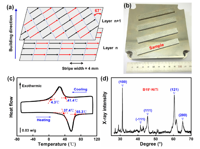
Fig. 1(a) illustrates the stripe rotation scanning strategy, deployed with a stripe width (laser scanning length) of 4 mm and a hatch rotation of 67°. The selected hatch rotation angle follows a principle that is not divisible by 360°, which aims at avoiding the overlap of laser tracks among multilayers and guaranteeing the blanket coverage melting of powders. Here the existing “Black Regions” are filled with black arrows and “White Regions” filled with red arrows which represent the orientation of laser tracks in each layer. The laser goes through “Black Regions” first, and then “White Regions”. Fig. 1(b) shows the SLM-produced lath-shaped NiTi samples built on NiTi substrate. Fig. 1(c) shows the DSC graph. It shows the Ms is 41.4 °C, Mf is 4.3 °C upon cooling, and the As is 37.4 °C, Af is 65.3 °C upon heating. Fig. 1(d) shows the XRD pattern of the SLM-NiTi after cooling in liquid nitrogen, which demonstrates the sample remains B19ʹ martensitic state at room temperature (RT$\widetilde{2}$0 °C).
Fig. 1. (a) The stripe rotation scanning strategy with stripe width of 4 mm and hatch rotation θ = 67°. The laser goes through “Black Regions” (black arrows) first and then “White Regions” (red arrows) in each layer. (b) The SLM-produced lath-shaped NiTi samples built on NiTi substrate. (c) DSC graph of the SLM-NiTi. (d) XRD pattern of the SLM-NiTi after cooled in liquid nitrogen.
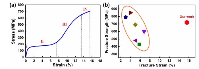
Fig. 2(a) shows the tensile stress-strain curve of the SLM-NiTi. It is seen that the sample exhibits a tensile fracture strain of 15.6% and fracture strength of 700 MPa. It is evident that the sample experiences a typical Lüders-like stress plateau over the martensite variant reorientation deformation [18]. The various stages are identified as the initial elastic deformation (stage Ⅰ), stress plateau associated with variant reorientation (stage Ⅱ), elastic deformation of oriented martensite (stage Ⅲ), and elastic/plastic deformation of oriented martensite (stage Ⅳ) [19]. Fig. 2(b) presents the comparison of tensile fracture strain and fracture strength between our work and the reported SLM-produced NiTi [10,20,21]. It is obvious that our SLM-NiTi possesses tensile fracture strain more than twice of the best reported ($\widetilde{7}$%), accompanied with high fracture strength. It is demonstrated that our SLM-NiTi overcomes the problem of poor tensile ductility in the reported SLM-produced NiTi.
Fig. 2. Tensile deformation behavior of the SLM-NiTi. (a) Tensile stress-strain curve at RT. (b) Comparison of tensile fracture strength and fracture strain between our work and reported SLM-produced NiTi [
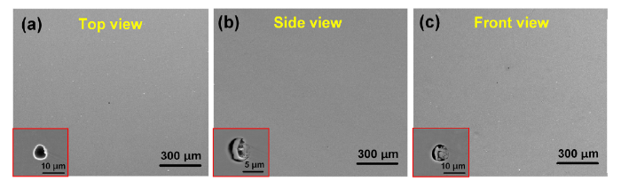
Fig. 3(a-c) shows the SEM micrographs from the top view, side view and front view of the SLM-NiTi, respectively. It is seen that there are no large-scale pores, impurities or cracks. From the inserts of further magnified views, few spherical micro-pores in diameter of 6-10 μm still exist. It is reported that the large-scale pores usually come from the trapped gases [22,23], which fails to escape due to the rapid solidification rate, and the cracks occur due to the high thermal stress, which is induced from large thermal gradient. During the line by line laser scanning process, melting-solidification of powders and remelting/reheating-cooling of solidification zones coexist. Thus the optimally proposed laser scanning length is conducive to improving the remelting or reheating temperature and reducing cooling rate, leading to the powders sufficient melting, trapped gases full escape and cracks being restrained.
Fig. 3. (a)-(c) SEM secondary electron micrographs of the SLM-NiTi from top view, side view and front view, respectively. The inserts are the micro-defects in magnified view.
The spherical micro-pores usually come from the fail-escaped dissolved gas from the liquid metal during fast solidification process, which also exist in traditional casting parts [24]. The escape rate of such micro-pores is quite low due to their small sizes [25], thus they are trapped in the SLM-NiTi. It is considered that the spherical micro-pores don’t have deadly disruption to the tensile ductility of the SLM-NiTi.
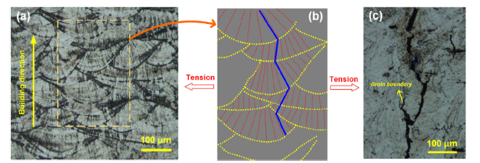
Fig. 4(a) shows the etched optical microscope image of the SLM-NiTi from the side view. Clearly we can see the sectorial molten pools with various morphologies among layers. To investigate the microstructures deeply, we made a schematic diagram as shown in Fig. 4(b). The yellow dotted lines represent the arched molten pool boundaries and the red dotted lines represent the radial grain boundaries in a molten pool. It is known that the direction of the grain growth varies with the direction of heat dissipation [26]. In the molten pool, laser spot is the highest temperature area compared with the surrounding areas. As a result, the grains grow epitaxially from the boundary to the center [27,28], leading to the radial grain structure.
Fig. 4. (a) Etched optical micrographs of the SLM-NiTi in side view. (b) Schematic diagram of microstructures in the partial area. The yellow dotted line represents the molten pool boundary; red dotted lines represent the radial grain boundary in a molten pool; the blue line represents the flexural zigzag grain boundary throughout multilayers. (c) Etched optical micrographs of the cracks upon tension.
The blue line in Fig. 4(b) represents the zigzag grain boundary throughout several layers along the building direction. The zigzag grain boundary is different from the common straight grain boundary in the reported SLM-produced metal materials [14,29]. Based on the above analysis, the grains grow along the direction of heat dissipation and the laser scanning direction could alter the direction of heat dissipation, thus altering the direction of the grain growth. Adopting appropriate interformational laser scanning direction of 67° could ensure the laser scanning path doesn’t overlap among multiple layers, leading to the zigzag grain boundary. Fig. 4(c) shows the crack path upon tension, which is also “zigzag” shape. Upon tension, the cracks prefer to propagate along the grain boundaries and the zigzag grain boundary obstructs the cracks to propagate smoothly [30], thus improving the tensile ductility of the SLM-NiTi.
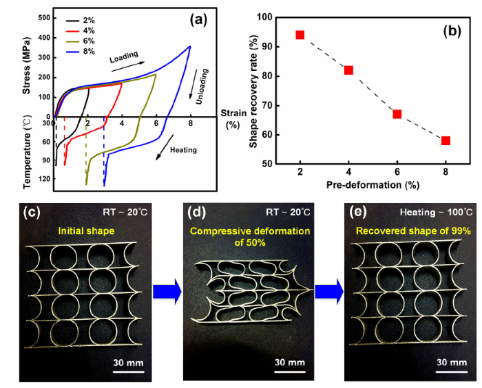
We explored the shape memory effects of the SLM-NiTi under different tensile pre-deformations. Fig. 5(a) shows the tensile loading-unloading curves under pre-deformation of 2%, 4%, 6%, 8% and subsequent shape recovery upon heating. There is irrecoverable strain after heated and the ratio of recoverable strain to unloaded strain is defined as shape recovery rate. Fig. 5(b) shows the shape recovery rate as a function of tensile pre-deformation. It is seen that the shape recovery rate decreases with the increasing pre-deformations. The shape memory rate is 95% when deformed by 2%, while the shape memory rate is 58% when deformed by 8%. The decrease of the shape memory rate results from the fact that more dislocations tend to slip with the tensile strain increasing due to the low yield stress of the SLM-NiTi [31,32]. The grain size of the SLM-NiTi is much larger than the traditionally-manufactured (forging and cold working) commercial NiTi and the coarse grains could significantly reduce the critical stress of dislocation slip and the yield strength of the SLM-NiTi [33]. Thus more dislocations and plastic deformations occur along with the martensite variant reorientation in the stage Ⅱ (Fig. 2(a)).
Fig. 5. (a) Stress-Strain-Temperature curves obtained by tensile loading-unloading-heating process of the SLM-NiTi. (b) Shape recovery rate as a function of tensile pre-deformation. (c) The initial shape of printed SLM-NiTi part. (d) The compressed SLM-NiTi part with deformation of 50%. (e) The recovered shape of the SLM-NiTi part after heating.
Fig. 5(c) shows the SLM- NiTi part of 90 mm × 80 mm × 10 mm in size and 0.5 mm in wall thickness. Fig. 5(d,e) shows the compression deformation - shape recovery of the SLM-NiTi part. The SLM-NiTi part exhibits shape recovery rate of 99% under the compressive deformation of 50%. Although the shape memory effect of the individual lath-shaped SLM-NiTi sample is not so satisfactory (shown in Fig. 5(b)), the SLM-NiTi part possesses excellent shape memory effect. It is speculated that although the total deformation is 50%, the deformations of partial areas are far below 50%, which may just experience the martensite variant reorientation without plastic deformation. As a result, the deformed part is able to return to its original shape upon heating.
In summary, by optimally combining the laser scanning length and laser scanning direction, the defect-less SLM-NiTi without unidirectional columnar grains was fabricated. The lath-shaped sample exhibits fracture strain of up to 15.6%, more than twice of the best reported. And the SLM-NiTi part with complex geometry displays an excellent shape memory effect (99% shape recovery upon heating after 50% compressive deformation). This study may contribute to promoting a more widely application of NiTi alloy assisted with additive manufacture.
This work was supported by the National Key R&D Program of China (No. 2018YFB1105100), the Science Foundation of China University of Petroleum, Beijing (No. 2462018BJC005), the Joint Fund of Ministry of Education for Pre-research of Equipment (No. 6141A020222), the fourth batch of pre-research projects for manned spaceflight (No. 040202).

 WeChat
/
| 〈 |
|
〉 |