


Influence of Temperature on Stacking Fault Energy and Creep Mechanism of a Single Crystal Nickel-based Superalloy
[Sugui Tian1, *  , Xinjie Zhu
1 , Jing Wu1 , Huichen Yu2 , Delong Shu1 , Benjiang Qian1 ]
, Xinjie Zhu|
|


The influence of temperatures on the stacking fault energies and deformation mechanism of a Re-containing single crystal nickel-based superalloy during creep at elevated temperatures was investigated by means of calculating the stacking fault energy of alloy, measuring creep properties and performing contrast analysis of dislocation configuration. The results show that the alloy at 760 °C possesses lower stacking fault energy, and the stacking fault of alloy increases with increasing temperature. The deformation mechanism of alloy during creep at 760 °C is γ′ phase sheared by <110> super-dislocations, which may be decomposed to form the configuration of Shockley partials plus super-lattice intrinsic stacking fault, while the deformation mechanism of alloy during creep at 1070 °C is the screw or edge super-dislocations shearing into the rafted γ′ phase. But during creep at 760 and 980 °C, some super-dislocations shearing into γ′ phase may cross-slip from the {111} to {100} planes to form the K-W locks with non-plane core structure, which may restrain the dislocations slipping to enhance the creep resistance of alloy at high temperature. The interaction between the Re and other elements may decrease the diffusion rate of atoms to improve the microstructure stability, which is thought to be the main reason why the K-W locks are to be kept in the Re-containing superalloy during creep at 980 °C.
Because single crystal nickel-based superalloys have excellent mechanical and creep properties at high temperature, they have been widely used in the preparation of blade parts of advanced aero-engines[1]. But as the aero-engine performance enhances, such as aero-engine power and thermal efficiency, the mechanical and creep properties of alloys at high temperature need to be further improved[2, 3, 4]. Adding refractory elements Re, W, or Mo may reduce the diffusion rate of the other elements in alloys because of their solid solution strengthening effects[5]. Especially, the element Re may obviously improve the creep properties of alloy at high temperature[6]. Additionally, the alloys with different compositions have various creep resistance, and the temperature tolerance of alloy may be improved with the increase of the refractory element Re[7, 8]. One of the reasons the element Re improves the creep resistance is that it may decrease the stacking fault energy (SFE) of alloys.
The alloys with different stacking fault energies display various mechanical and creep properties[9] due to the different moving patterns of dislocation during deformation[10, 11, 12], and therefore, the stacking fault energy of alloys is an important physical character related to the mechanical properties.
Some elements, such as Cr, Mo, Ti and W, may reduce the stacking fault energy of nickel[13, 14, 15], which results in the various deformation mechanisms of the alloys during creep. It was indicated[16, 17] that the deformation feature of some alloys during primary creep is dislocation slipping in γ matrix, and the creep resistance of alloys at high temperature may be improved by adding the element Re, which is mainly distributed in γ matrix to reduce the stacking fault energy and inter-diffusion coefficient of the other elements[18, 19, 20]. Moreover, the resistance of the dislocations climbing and cross-slipping in γ matrix is also affected by the stacking fault energy[16, 21, 22].
Some literature reported[23, 24, 25, 26] that the deformation mechanism of alloy in the primary stage of creep at 750 ° C is the activation of < 112> dislocations with extended ribbon feature linked by anti-phase boundary, super-lattice extrinsic and intrinsic stacking faults or complex stacking faults (CSF). In the primary stage of creep at 750 ° C/750 MPa, the deformation mechanism of CMSX-4 alloy is mainly < 112> dislocation ribbons shearing through the γ /γ ′ phases[27, 28]. The ribbons consist of four dislocations in the γ ′ phase, and separated by super-lattice intrinsic stacking faults (SISF) or anti-phase boundary (APB)[29].
Due to the work of aircraft engines in service undergoing the processes from the intermediate temperature to high temperature, the blade parts in aero-engines had to bear the various work conditions from start to stable course. It was reported[7, 8] that the configuration of < 112> partials plus stacking fault is formed in the alloy during creep at 800 ° C, while the deformation mechanisms of the alloy during creep at 1070 ° C is only < 110> super-dislocation shearing into γ ′ phase. This indicates that the alloy displays various deformation mechanisms during creep at different temperatures. However, the dependence of the stacking fault energy of alloy on temperatures and the influence of stacking fault energy on deformation mechanisms are not clear.
By transmission electron microscope observations and computer simulated images of dissociation widths, the stacking fault energy of alloy is determined as a function of temperature[30]. Moreover, adding 10% Co (mass fraction, %) makes the stacking fault energy in binary Ni-Cr solid solutions drop from 75 to 56 mJ/m2[31, 32]. Adding some elements, such as Ti, Al, Ta, Mo and W dissolving in the γ ′ /γ phases, decreases the stacking fault energy of alloy to 20-30 mJ/m2[33]. Because stacking fault energy has an important effect on the deformation mechanisms and life of alloys during creep, it is very interesting to study the influence of temperatures on the stacking fault energy and deformation mechanisms of alloys.
In this study, by creep properties measurement of a single crystal nickel-based alloy at different temperatures, microstructure observations and contrast analysis of dislocations configuration, the stacking fault energies of the alloy at different temperatures were calculated based on thermodynamics method, and the influence of temperatures on the stacking fault energy and deformation mechanism of the alloy during creep was investigated.
A single crystal nickel-based superalloy containing 2% Re with [001] orientation had been prepared by selecting crystal method in a vacuum directional solidification furnace under a high temperature gradient. The nominal chemical composition of the alloy is given inTable 1. The growing direction of the single crystal bars was determined to be within 6° deviating from [001] orientation by Laue-back reflection. The used heat treatment regime of the single crystal bars is given as follows: 1290 ° C, 1 h + 1300 ° C, 2 h, AC (air cooling) + 1315 ° C, 4 h, AC + 1120 ° C, 4 h AC + 870 ° C, 32 h, AC.
| Table 1. Chemical compositions of the single crystal nickel-based superalloy (mass fraction, %) |
After full heat treatment, the bars of the single crystal nickel-based alloy were cut into the plate-like creep specimens along (100) crystal plane of the [001] orientation; the specimens have the cross-section of 4.5 mm × 2.5 mm and the gauge length of 20.0 mm. After the surface of the specimens was mechanically ground and polished, the uni-axial constant load tensile testing was performed in a creep testing machine of GWT504 model. Under the conditions of 760 ° C/810 MPa, 980 ° C/300 MPa and 1070 ° C/160 MPa, the creep properties of the alloy were measured to plot the creep curves. The microstructures of the alloy after being crept up to fracture under different conditions were observed by transmission electron microscopy (TEM), combined with the contrast analysis of dislocation configuration, and the deformation mechanisms of the alloy under different conditions were investigated. Moreover, the stacking fault energy of the alloy at different temperatures was calculated by thermodynamics methods, and the influence of temperatures on the stacking fault energy and creep mechanism of the alloy was investigated.
The stacking fault energy is an important physical character of alloys. The mechanical and creep properties of alloys are closely related to their SFE. Therefore, the influence of the stacking fault energy on the mechanical properties of alloys has been widely investigated.
For the metals with FCC structure, the {111} close-packed planes are the ones that slip easily. During deformation, the regular stacking model of the close-packed structure is changed when the stacking fault is formed in the planes, which is equivalent to one layer ε atoms with HCP structure inserting into γ atoms on {111} planes of the FCC structure. The stacking fault energy may be calculated according to the difference of Gibbs free energies between two layers of γ atoms and one layer of ε atoms. Therefore, the stacking fault energy (γ SF) of alloy with FCC structure may be expressed as[34]
where V is the molar volume, and
The change of Gibbs free energy originating from the substitutional atoms is given as follows:
 |
Here,
Here, Δ Gchm is the change of the free-energy originating from Suzuki segregation; Δ Gsuris the surface free-energy originating from the concentration difference of the atoms between the matrix and the stacking fault region, Δ Gels is the elastic free-energy coming from the difference of the atoms' size, and the surface free-energy (Δ Gsur) and the elastic free-energy (Δ Gels) in the calculation may be ignored due to a smaller energy acting between the segregation atoms. Therefore, the stacking fault energy of Ni-Al-Me ternary alloy may be calculated according to Eqs. (1), (2), (3), (4) and (5), in which the used parameters are taken from literature[30, 36, 37].
Because the decomposition of dislocation occurs mainly in γ ′ phase of alloy during creep, the stacking fault energy of γ ′ phase is thought to be the one of the alloy. The alloy is regarded as a solid solution in the calculation, according to the partitioning ratios of the elements Cr, Co, W, Mo, Al, Ta and Re in γ ′ /γ phases in the alloy[38]. The stacking fault energies of γ ′ phase in Ni-6%Al-1%Me (Me = Cr, Co, Ta, Mo, Re) and Ni-6%Al-1%W ternary alloys at different temperatures are calculated, as shown in Fig. 1. According toFig. 1, the elements Ta, Cr, Co, Mo and Re, relative to the element W, may reduce the stacking fault energy of the Ni-6%Al-1%Me ternary alloy, and the element Re reduces the one to a greater extent.
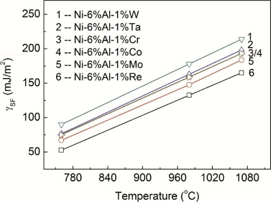 | Fig. 1. Stacking fault energy (SFE) of the Ni-6%Al-1%Me alloys at different temperatures. |
Moreover, the ratio in the stacking fault energies of Ni-6%Al-1%Me (Me = Cr, Co, Ta, Mo, Re) to Ni-6%Al-1%W ternary alloys at different temperatures is defined as the equivalent conversion coefficient of each element; the ones (Ai) at different temperatures are listed inTable 2. It is shown from Table 2 that the Ni-6%Al-1%Me (Cr, Co, Ta, Mo, Re) ternary alloys at different temperatures display the various equivalent conversion coefficients (Ai).
| Table 2. Equivalent conversion coefficients of components Me(i) at different temperatures |
Further, the product of the equivalent conversion coefficients and mass fraction of each element is summed to obtain the total concentration Me(T) of the elements in Ni-6%Al-x%Me (Me = Cr, Co, W, Ta, Mo, Re) alloy, which is expressed as Eq. (6):
where [C%] is the equivalence concentration of elements and A(T)i is the equivalent conversion coefficients of the component (i) (i = Cr, Co, W, Ta, Mo, Re). The equivalent conversion coefficients (Ai) of the elements (i) at various temperatures are given inTable 2. The C in Eq. (6) is the mass fraction of the elements in the alloy, and the values ofC are given in Table 1. Therefore, the stacking fault energy of the multi-component alloy at different temperatures may be calculated by the total concentration Me(T) of elements in the alloy substituting into Eq. (1). The stacking fault energies of the multi-component alloy at 760, 980 and 1070 ° C are calculated and listed in Table 3.
| Table 3. Stacking fault energy of γ ′ phase in the used alloy at different temperatures |
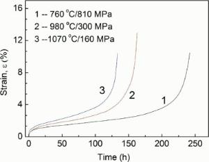
The creep curves of the alloy at 760 ° C/810 MPa, 980 ° C/300 MPa and 1070 ° C/160 MPa are measured as marked by the numbers 1, 2, and 3 in Fig. 2, respectively, which indicates that the strains and rates of the alloy increase with increasing creep temperatures, wherein the strain rates of alloy during steady state creep at 760 ° C, 980 ° C and 1070 ° C are measured to be 1.58 × 10⁻⁶/h, 1.98 × 10⁻⁶/h and 2.26 × 10⁻⁶/h, respectively, and the creep lifetimes of alloy at temperatures stated above are measured to be 241 h, 163 h and 133 h, respectively.
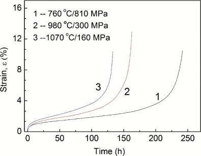 | Fig. 2. Creep curves of the alloy at different conditions. |
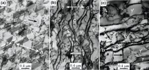
After the alloy is crept up to fracture at different temperatures, the microstructures in the samples near the fracture region are shown in Fig. 3, where the observed surfaces of the specimens are parallel to the (100) plane. The morphology of alloy crept for 241 h up to fracture at 760 ° C/810 MPa is shown in Fig. 3(a), where the direction of the applied stress is marked by the arrows. The morphology indicates that the γ ′ phase in alloy remains still the cubical configuration; dislocation tangles are filled up in γ matrix channels as shown in the region A; and some super-dislocations have sheared into γ ′ phase, as marked by the arrow in Fig. 3(a). Moreover, a significant amount of stacking fault stripes appear within the cubical γ ′ phase, as marked in the region B of Fig. 3(a). Because the stripes of the stacking fault display the symmetrical feature and the outside stripes in the stacking fault region exhibit the dark contrast, the stacking fault in the alloy is identified as the super-lattice intrinsic stacking fault (SISF).
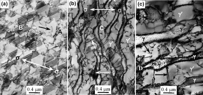 | Fig. 3. Microstructures after the alloy crept up to fracture under different conditions: (a) 760 ° C/810 MPa, (b) 980 ° C/300 MPa, (c) 1070 ° C/160 MPa. |
The microstructure of the alloy crept for 163 h up to fracture at 980 ° C/300 MPa is shown inFig. 3(b), where the direction of the applied stress is marked by the arrow. It is indicated that the γ ′ phase in alloy has transformed into the rafted structure along the direction perpendicular to the stress axis, and the dislocation networks are distributed in the interfaces of the rafted γ ′ /γ phases. In the latter stage of creep, some dislocation networks in the local region have been destroyed, as marked by the horizontal arrow. Significant amounts of dislocations in γ matrix are piled up in the interfaces of γ ′ /γ phases, which may cause the stress concentration. When the value of stress concentration exceeds the yield strength of alloy, the dislocations may shear into the γ ′ phase from the interfaces, where the networks are damaged. The super-dislocation shearing into the γ ′ phase is marked by the inclined arrow. As the creep goes on, the slipping of dislocations is alternately activated, along the directions at 45° angles relative to the stress axis, to shear the rafted γ ′ phase under the action of the bigger shearing stress, which results in the contortion of the rafted γ ′ /γ phases, as shown in the region C of Fig. 3(b).
The microstructure of the alloy crept for 133 h up to fracture at 1070 ° C/160 MPa is shown inFig. 3(c), indicating that the γ ′ phase in alloy has transformed into the thicker rafted structure due to the region near fracture bearing a bigger effective stress, and the regular dislocation networks are distributed in the interface of γ ′ /γ phases, as shown in the region D. Moreover, some screw or edge super-dislocations had sheared into the rafted γ ′ phase, as marked by the inclined and horizontal arrows. Compared to the rafted γ ′ phase in Fig. 3(b), the thickness and twisted extent of the rafted γ ′ phase in Fig. 3(c) increases, which is attributed to the bigger plastic deformation occurring in the necking region.
After the alloy is crept for 241 h up to fracture at 760 ° C/810 MPa, the dislocation configuration within γ ′ phase is shown in Fig. 4, indicating that the partials and stacking fault stripes are distributed within the γ ′ phase; the partials in two sides of the stacking fault stripes are defined as the dislocations A and B, respectively. Moreover, the super-dislocation shearing into γ ′ phase is marked by the letter C. The stacking fault stripes display contrast when the diffraction vector g is 002 and 020, respectively, as shown inFig. 4(a) and (b), and the contrast of the stacking fault stripes disappears when diffraction vector g is
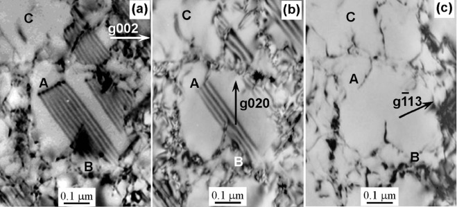 | Fig. 4. Dislocation configuration within the γ ′ phase after alloy crept for 241 h up to fracture at 760 ° C/810 MPa: (a)g = 002, (b) g = 020, (c)g= |
The dislocation A displays contrast when the diffraction vector g is 002 and
It is a reasonable consideration that when the γ ′ phase is sheared by [10
The super-dislocation C shearing into the cubical γ ′ phase displays contrast when the diffraction vector g is 020, as shown in Fig. 4(b), but the contrast of the dislocation C disappears when the diffraction vector g is 002 and
It is a reasonable consideration that the initial slipping plane of dislocation C with Burgers vector bC = [110] is (11
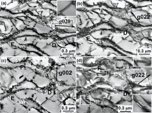
After the alloy is crept for 163 h up to fracture at 980 ° C/300 MPa, the dislocation configurations within the rafted γ ′ phase are shown in Fig. 5, in which some dislocations shearing into γ ′ phase are marked by the letters D, E and F, respectively. When the diffraction vector g is 020, 02
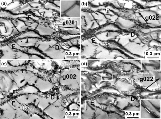 | Fig. 5. Dislocation configurations within the γ ′ phase after the alloy crept for 163 h up to fracture at 980 ° C/300 MPa: (a) g = 020, B = [100], (b) g=02 |
The dislocations E and F display contrast when the diffraction vector g is 020, 02
On the other hand, the super-dislocations shearing into γ ′ phase may decompose to form the configuration of the partial plus APB, such as the dislocations D, E and F displaying the decomposed feature. Although the dislocations E and F possess the same Burgers vector
Although the dislocations D and F display the decomposed feature, as shown in the magnified configurations in the upper right of Fig. 5(a) and (d), respectively, the dislocation F displays the single line contrast, as shown in Fig. 5(a), which is attributed to their various decomposed planes under a certain diffracted condition. Moreover, it is indicated that the decomposed widths of dislocations D and F on (100) and (001) planes are measured to be about 3 nm as shown in Fig. 5(a) and (d). But the decomposed width of the dislocation E on (111) plane is about 5 nm as shown in the bottom right of Fig. 5(d). The decomposition reaction of the dislocations E and F on the (111) and (001) planes is given as follows:
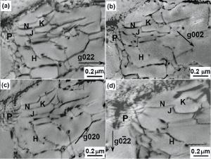
After being crept for 133 h up to fracture at 1070 ° C/160 MPa, the deformation feature of alloy is shown in Fig. 6. It can be understood that some denser dislocation networks are distributed in the interface of γ ′ /γ phases, as marked in the region P of Fig. 6. Therefore, it may be determined that the semi-coherent interfaces remain in between the γ ′ /γ phases. Moreover, the super-dislocation shearing into the γ ′ phase is marked by the letter H, and the components in the network-like dislocations are marked by the letters K, J and N, respectively.
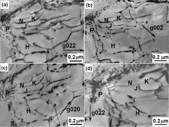 | Fig. 6. Dislocation configuration within the γ ′ phase after alloy crept for 133 h up to fracture at 1070 ° C/160 MPa: (a) g = 022, (b) g = 002, (c) g = 020, (d) g=0 |
When the diffraction vector g is 022, 020, 0
When the diffraction vector g is 022, 002 and 020, the dislocation K displays contrast, as shown in Fig. 6(a-c), whereas the contrast of the dislocation K disappears when the diffraction vector g is 0
According to the analysis stated above, no slipping of dislocations is detected on {100} planes of the alloy during creep at 1070 ° C, which suggests that if some dislocations may cross-slip from {111} to {100} planes to form the K-W locks during creep, the dislocation in the locks may be activated for re-slipping on {111} planes as the creep temperature increases to 1070 ° C.
The stacking fault energy is an important physical character, which has an obvious effect on the deformation mechanism and resistance of alloy during creep. Therefore, the alloys with different stacking fault energies display the various deformation mechanisms and resistances during creep. On the one hand, the resistance of dislocation moving in γ matrix may increase with the alloying extent of the elements. On the other hand, the deformation mechanism of alloy during creep may change with the stacking fault energy, especially the stacking fault energy of alloy with the same composition changes with temperatures, as shown in Table 3. It is indicated from Table 3 that the single crystal alloy at 760 ° C displays a lower stacking fault energy, and the stacking fault energy of the alloy increases with increasing temperature. Therefore, the various deformation mechanisms occur in the alloy during creep at different temperatures, as shown in Fig. 4, Fig. 5 and Fig. 6.
According to the contrast analysis of dislocation configuration, the alloy at 760 ° C has a lower stacking fault energy; the deformation mechanism of alloy with lower stacking fault energy during creep is the γ ′ phase sheared by the < 110> super-dislocation, which may be decomposed to form the configuration of (1/3) < 112> Shockley partials plus SISF. The stacking fault energy of alloy at 980 ° C increases to 281.2 mJ/m2, which increases the resistance to dislocation decomposition, so that the configuration of (1/2) < 110> partials plus the anti-phase boundary (APB) is formed in the alloy when < 110> super-dislocation shearing into γ ′ phase is decomposed, such as the dislocations E and F in Fig. 5(d). But the deformation mechanism of the alloy during creep at 1070 ° C is the super-dislocations with screw or edge features shearing into the γ ′ phase, as shown in Fig. 6, due to the stacking fault energy of alloy increasing to 349.1 mJ/m2.
The analysis stated above indicates that the motion mode of dislocation during creep is closely related to the stacking fault energy of alloy[2, 3]. The activated dislocations during creep are easily decomposed in the alloy with lower stacking fault energy to form the configuration of Shockley partials plus SISF, and the alloy displays bigger expanding width of dislocation, as shown in Fig. 4(a). The expanding dislocation cannot cross-slip due to the one being hard to concentrate; therefore, the configuration of dislocation may improve the creep resistance of alloy. The decomposed resistance of dislocation increases with increasing temperature and stacking fault energy of alloy, so that a few < 110> super-dislocations shearing into γ ′ phase during creep at 980 ° C/300 MPa is decomposed to form the configuration of (1/2) < 110> partials plus APB, and no configuration of the partials plus SISF is detected in the alloy. The stacking fault energy of alloy increases as the creep temperatures go up further to 1070 ° C, and the super-dislocation shearing into γ ′ phase cannot be decomposed, as shown in Fig. 6. Therefore, it is thought that the deformation mechanisms of alloy during creep at different temperatures are the < 110> super-dislocation shearing into γ ′ phase, and the decomposed modes of dislocations are related to the temperature and stacking fault energy of alloy. The dislocation shearing into γ ′ phase may be decomposed to form the configurations of the partials plus SISF or partials plus APB as the stacking fault energy of alloy increases. Both the SISF and the APB formed from the dislocation decomposition may hinder dislocation motion to improve the creep resistance of alloy.
During creep, < 110> dislocations are easily activated on {111} plane of γ ′ phase with Ll2structure. When the dislocations shearing into γ ′ phase are decomposed to form the partials, super-lattice intrinsic stacking fault (SISF), anti-phase boundary (APB) or complex stacking fault (CSF) may form in between the partials according to the differences of the stacking fault energy and deformation conditions[39]. The schematic diagram of dislocations shearing into γ ′ phase on various planes is shown in Fig. 7, where the direction of dislocation movement is marked by the arrows. At 760 ° C, the alloy possesses lower stacking fault energy of 128.1 mJ/m2. The super-dislocation shearing into γ ′ phase may be decomposed on {111} planes to form in the configuration of the partials plus SISF due to their close stacking structure, as shown in Fig. 4, which is schematically shown in Fig. 7(a). Because it is very difficult for the configuration of partials plus stacking fault to bundle up, the cross-slipping of the dislocations on {111} planes may be restrained to improve the creep resistance of alloy.
 | Fig. 7. Schematic diagrams of dislocations slipping and decomposing on different planes of γ ′ phase in the alloy during creep: (a) decomposition of dislocation on (11 |
As the creep temperature increases to 980 ° C, the stacking fault energy of the alloy increases to 281.2 mJ/m2, and the dislocation shearing into γ ′ phase cannot be decomposed to form the partials plus SISF. But the super-dislocation shearing into γ ′ phase may be decomposed to form the configuration of (1/2) < 110> plus APB, as shown in Fig. 5. Moreover, no complex stacking fault (CSF) is detected in the alloy because the formation of the configuration needs a bigger energy.
It is thought by analysis that the probability of forming various plane-defects during creep depends on the needed energy[39]. During creep at 760 ° C, the configuration of the partial plus SISF forms when the dislocation shearing into γ ′ phase is decomposed on the {111} plane as shown in Fig. 4, which needs only a lower energy of about 13 mJ/m2[40]. But stacking fault energy of alloy increases with increasing temperature, and the decomposed width of dislocation diminishes due to the increase of the decomposed resistance. Therefore, the configurations of the partials plus SISF or partials plus APB form in the alloy during creep at 760 and 980 ° C, respectively, as shown in Fig. 4 and Fig. 5. The configuration displays the plane core structure of dislocations, as schematically shown in the right side on (11
Moreover, the screw super-dislocations shearing into γ ′ phase of alloy during creep at 760 and 980 ° C may cross-slip from {111} to {100} planes to form the K-W locks, or the ones may be further decomposed to form the configuration of K-W locks plus APB. The configuration of the K-W locks is a sessile dislocation with non-plane core structure, as schematically shown on the right side on (11
On the one hand, adding element Re may reduce the stacking fault energy and enhance the solid solution strength extent to improve the creep resistance of alloy[17, 18]. On the other hand, the Re atomic clusters in γ matrix[41, 42] and the interaction of the Re with other atoms may decrease further the diffusion rates of other elements to improve the microstructure stability of alloy. Once the K-W locks are formed in the alloy, they may be kept because the interaction of the Re with the other atoms reduces their diffusion rates during creep at 980 ° C. It is thought that the better microstructure stability of alloy is attributed to the interaction of the Re with other elements. Therefore, the dislocations in the K-W locks cannot be re-activated to release the locks under the action of the thermal activation during creep at 980 ° C, so that the K-W locks may be kept in the alloy, such as the dislocations D and F in Fig. 5, which is schematically marked by the letter N in Fig. 7(c).
It is a reasonable consideration that < 110> dislocations in alloy during creep at 1070 ° C may also cross-slip from {111} to {100} planes to form K-W locks, but the thermal activation may promote the dislocations in K-W locks for re-slipping on {111} planes to release the K-W locks. This is the main reason why no K-W locks are detected in the alloy during creep at 1070 ° C. Therefore, it is thought that temperature has an important effect on the creep behaviors and deformation mechanism of alloy[10, 43, 44].
Although the super-dislocation shearing into γ ′ phase may be decomposed to form the configuration of the partials plus APB, the decomposition on various planes needs to overcome the different resistances. It is indicated that the energy needed is about 142 mJ/m2 when the < 110> dislocation on {111} planes is decomposed to form the partials plus APB[40]. Although the decomposition forming the configuration of the partials plus APB needs a bigger energy, the migration of the atoms occurs easily in the {111} decomposed plane with close packed structure; the combined role of the bigger APB energy and easy migration feature of atoms results in the dislocations shearing into γ ′ phase being decomposed on {111} plane to form the configuration of (1/2) < 110> partials plus APB with decomposed width of about 5 nm, such as the dislocation E in Fig. 5. The configuration of (1/2) < 110> partials plus APB on {111} planes possesses the planar core structure, as schematically indicated in Fig. 7(b).
The < 110> dislocation decomposing on {100} planes to form the APB needs only a smaller energy of about 28 mJ/m2[39], and therefore, the configuration of the (1/2) < 110> plus APB may stably exist on the {100} plane, such as the dislocation F in Fig. 5. Although the < 110> dislocations shearing into γ ′ phase may decompose on {100} plane, the decomposed ones are not easily expanded on the plane due to their non-close-packed structure, which results in the decomposed width of dislocation on {100} plane being only about 3 nm, as shown in the dislocations D and F of Fig. 5.
(1)The alloy at 760 ° C possesses lower stacking fault energy, and the stacking fault energy of alloy increases with increasing temperature. The creep mechanism of alloy at 760 ° C is γ ′ phase being sheared by < 110> super-dislocations, which may be decomposed to form the configuration of Shockley partials plus SISF.
(2)During creep at 980 ° C, the rafted γ ′ phase is sheared by < 110> super-dislocations with screw or edge features, which may be decomposed on the {111} and {100} planes to form the configuration of (1/2) < 110> plus APB. As the temperature increases to 1070 ° C, the creep mechanism of alloy is the rafted γ ′ phase sheared by the screw or edge super-dislocation on {111} planes.
(3)During creep at 760 and 980 ° C, some super-dislocations shearing into γ ′ phase may cross-slip from the {111} to {100} planes to form the K-W locks, and the ones on {100} planes may be decomposed to form the configuration of (1/2) < 110> plus APB; the K-W locks with non-plane core structure may restrain the slipping and cross-slipping of dislocations to enhance the creep resistance of alloy at high temperature.
(4)Adding the element Re may reduce the stacking fault energy of alloy to enhance the creep resistance, wherein the interaction between the Re and other atoms decrease the diffusion rate of elements to improve the microstructure stability, which is the main reason the K-W locks are kept in the Re-containing alloy during creep at 980 ° C.
This work was financially supported by the National Natural Science Foundation of China(Grant No. 51271125).
The authors have declared that no competing interests exist.
| [1] |
|
| [2] |
|
| [3] |
|
| [4] |
|
| [5] |
|
| [6] |
|
| [7] |
|
| [8] |
|
| [9] |
|
| [10] |
|
| [11] |
|
| [12] |
|
| [13] |
|
| [14] |
|
| [15] |
|
| [16] |
|
| [17] |
|
| [18] |
|
| [19] |
|
| [20] |
|
| [21] |
|
| [22] |
|
| [23] |
|
| [24] |
|
| [25] |
|
| [26] |
|
| [27] |
|
| [28] |
|
| [29] |
|
| [30] |
|
| [31] |
|
| [32] |
|
| [33] |
|
| [34] |
|
| [35] |
|
| [36] |
|
| [37] |
|
| [38] |
|
| [39] |
|
| [40] |
|
| [41] |
|
| [42] |
|
| [43] |
|
| [44] |
|