
Characteristics of Twin Lamellar Structure in Magnesium Alloy during Room Temperature Dynamic Plastic Deformation
[Lou Chao, Zhang Xiyan*  , Duan Gaolin, Tu Jian, Liu Qing]
, Duan Gaolin, Tu Jian, Liu Qing]
|
|


The microstructures of the as-rolled magnesium alloy subjected to dynamic plastic deformation along the rolling direction have been investigated. Mostly one ![]() twin variant or a twin variant pair is activated in a grain, leading to a parallel
twin variant or a twin variant pair is activated in a grain, leading to a parallel ![]() twin lamellar structure. At the stage of twinning-dominated deformation (
twin lamellar structure. At the stage of twinning-dominated deformation (![]() twin activity. When plastic strain is greater than ∼8%, the twin lamellar structure disappears because the volume fraction of twins almost saturates at a value of ∼90%.
twin activity. When plastic strain is greater than ∼8%, the twin lamellar structure disappears because the volume fraction of twins almost saturates at a value of ∼90%.
Deformation twinning plays an important role in the deformation of hexagonal close-packed (hcp) metals because of their limited slip systems [1], [2], [3] and [4]. Due to the complicated interaction between twinning and slip, deformation twinning can effectively strengthen or weaken the strength and ductility of hcp metals [3]. For pure Mg and Mg alloys, which have the low stacking fault energy, twinning plays an important role during deformation, particularly at low temperatures and high strain rates [5] and [6]. Generally three types of twins can be activated in magnesium alloys: extension twins, compression twins on the and planes, and double twins, including and double twins [7], [8] and [9]. twinning is thought to be activated more frequently in several types of twins of Mg alloys. Due to the polar characteristic of twinning, the deformation texture attributable to twinning always forms in wrought magnesium and magnesium alloys and results in high asymmetry and anisotropy in the mechanical properties of metals [10] and [11]. Moreover, the twin boundaries acted as effective barriers for slip also play an important role in the deformation mechanisms of hcp materials [5], [12] and [13]. Song and Li [14] investigated the effect of twin spacing on the deformation behavior of nano-twinned magnesium using molecular dynamics simulation and found that there is a pronounced shift in its mechanical behavior when twin spacing is smaller than 2.9 nm. Therefore, it is crucial to understand the twinning behavior in hcp materials, for microstructural design and applications. For a face-centered cubic (fcc) polycrystalline Cu subjected to a dynamic plastic deformation, twin boundary spacing decreases from 48 to 14 nm with increasing strain and steps into saturated state when deformation strain is greater than 1.2 [15]. When a nickel-base HASTELLOY C-2000 alloy was subjected to a surface severe plastic deformation treatment, the twin spacing decreased as the position became closer to the impacted surface [16]. However, a little has been reported so far on hcp metals. For the Mg alloys of hcp crystal structure, the development of the microstructural morphology caused by twins is also closely related to plastic strain. Hence, it is of great interest to investigate the microstructural evolution of Mg alloys during deformation. twin nucleation and propagation can be dramatically enhanced at dynamic rates, and contraction and secondary twinning are not favored [17]. So to facilitate twinning, dynamic plastic deformation (DPD) was employed to deform samples to several strains in this study.
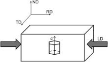
The hot-rolled AZ31 Mg alloy sheet (Mg–3%Al–1%Zn, wt%) has twin-free equiaxed grain structure ( Fig. 1(a)) and an average grain size of 34 μm calculated by the linear intercept method. As generally observed in annealed AZ31 sheets, the basal {0001} planes of this sheet were aligned almost parallel to the rolling plane, as shown in Fig. 1(b). Cylinders (8 mm in diameter and 12 mm in height) were cut from this sheet along the rolling direction (RD) ( Fig. 2). Samples were subjected to DPD just once with Instron Dynatup 8120 testing machine at room temperature and the strain rate is about 103 s-1. The deformation strain was defined as ε = ln( L0/ Ld), where L0 and Ld are the initial and final height of the samples, respectively. The initial texture was measured by X-ray diffraction in a Rigaku D/max-2500 PC. Scanning electron microscopy–electron back-scattered diffraction (SEM–EBSD) was utilized to analyze the microstructure and texture of samples after deformation. The deformation within the samples under uniaxial compression was of inhomogeneity, so EBSD data was acquired from the center of the cross section ( i.e. the ND–RD plane) of the impacted sample. EBSD scans were performed by FEI Nova400 FEG–SEM on the unit for 300 × 300 with a step size of 1 μm and EBSD information was acquired with Channel 5 software. The specimens for EBSD were prepared by standard metallographic polishing, then electropolished by using the commercial AC 2 electrolyte for 60 s at 20 V and 20 °C.
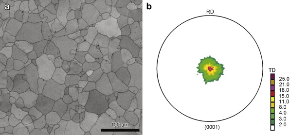 | Fig. 1. Microstructural characteristics of the as-rolled material: (a) EBSD map, (b) (0001) pole figure. |
 | Fig. 2. Schematic illustration of the sample orientations used for DPD testing. RD, TD and ND represent the rolling direction, the transverse direction and the normal direction, respectively; the arrows indicate the loading direction. |
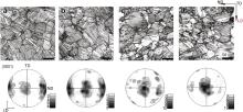
Fig. 3 shows the optical micrographs of DPD samples observed in the longitudinal section with different strain levels and the texture evolution during deformation. Only twin is generated in grains during deformation. At the early stage of deformation, a lot of twins are activated and the twin morphologies developed in a grain are almost parallel to each other, as shown in Fig. 3(a) and (b). With further strain, irregular twin shapes are obtained due to the coalescence of growing twins, as shown in Fig. 3(c) and (d). For compression perpendicular to the c-axis in the hcp crystal structure, the c-axis of the twinned region is oriented toward the loading direction (LD). The difference of twin textures with different strains ( Fig. 3) can be interpreted based on the different volume fractions of twins. For strain ε > ∼8%, the as-rolled texture with the c-axis aligned parallel to the normal direction (ND) is transferred to the twin texture with the c-axis aligned parallel to the RD ( Fig. 3(d)).
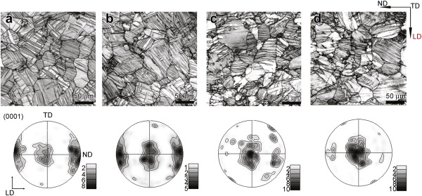 | Fig. 3. EBSD maps and (0001) pole figures of AZ31 samples with different strains: (a) ε = 2.1%, (b) ε = 4.3%, (c) ε = 6.5%, (d) ε = 8.3%. LD represents loading direction. |
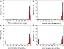
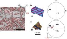
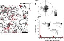
Theoretically, a grain could twin on six equivalent twinning planes with one shear direction of, but the selection of twin variants depends on the strain path [18] and [19]. Fig. 4 shows the misorientation angle distributions of AZ31 samples with different strains. As shown in Fig. 4(a), a local peak at 80°–90° increases rapidly with increasing strain to ∼4% ( Fig. 4(b)) due to twin nucleation, and then decreased as the interaction of growing twins ( Fig. 4(c) and (d)). For Mg alloys, several misorientation relationships can be generated between two twin variants, i.e. 0° or 7.4° relationship between same twin variant pairs, and 60° or 60.4° relationship between different twin variant pairs [17] and [19]. But the misorientations for the latter two are so close that it is hard to distinguish in EBSD map [20]. For compression perpendicular to the c-axis, most grains included just one twin variant or a twin variant pair, so these twin bands were almost parallel to each other, such as grain A in Fig. 5(a), and orientations of grain matrix and the activated variants are illustrated in Fig. 5(b). So a local peak at 80°–90° decreases as the intersection or coalescence of twins with further strain, and a misorientation relationship about 7.4° is generated, leading to a rapid increase in the peak of low misorientation angles about 0°–10° ( Fig. 4). As listed in , some grains generate different twin variants, such as grain B in Fig. 5(a), and its orientation is illustrated in Fig. 5(c). So a local peak at ∼60° increases slightly with strain. In addition, a local peak at low angles (<5°) results from the dislocation pileups developing at the twin boundaries and the sessile dislocations within twins. It should be pointed out that the similar twin lamellar structure in our experiments has also been gotten by quasi-static compression (QSC), in which the loading direction is perpendicular to the c-axis of crystal lattice [19] and [20].
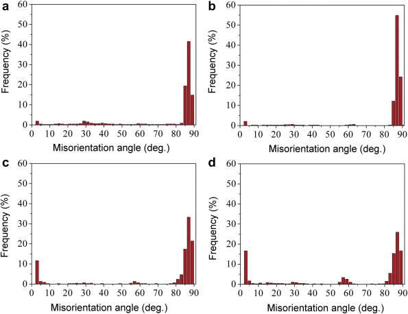 | Fig. 4. Misorientation angle distributions of AZ31 samples with different strains: (a) ε = 2.1%, (b) ε = 4.3%, (c) ε = 6.5%, (d) ε = 8.3%. The rotation axis distributions in the crystal coordinate system indicate the different misorientation relationships. |
 | Fig. 5. (a) Microstructure of DPD sample with ε = 4.3%, red lines indicate |
| Table 1. Statistical results of the number of twinned grains |
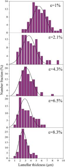
Lamellar thickness was measured by an average linear intercept with the aim of analyzing the relationship between the microstructural morphology and plastic strain. To ensure statistical validity, a large number of twinned grains have been investigated in five samples, corresponding to different strain levels of 1%, 2.1%, 4.3%, 6.5% and 8.3%, respectively, as listed in . Nearly all grains generate twins in the statistical results, and a few grains do not form twins because grain orientations have a large deviation from ideal orientation of basal texture. The statistical results of lamellar thickness are presented in Fig. 6. The average lamellar thickness decreases from 5.55 μm at ε = 1% to 2.49 μm at ε = 8.3%. Meanwhile, the distribution range of lamellar thickness shrinks from 2–10.2 μm at ε = 1% to 1–4.85 μm at ε = 8.3%. Lamellar thickness decreases significantly with increasing strain.
 | Fig. 6. Statistical results of lamellar thickness with different strains. |
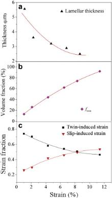
Fig. 7(a) shows the average lamellar thickness with different strains. It is obvious that lamellar thickness decreases with increasing strain to ∼8%. But the contribution of twinning to the deformation rapidly decreases with increasing strain because the capacity for twinning is exhausted locally within grains ( Fig. 7(b)). When plastic strain exceeds ∼8%, twin morphologies become irregular and the amount of twin boundaries finally decreases as twin-to-twin interactions causes a change in the misorientation angles of twin boundaries. As shown in Fig. 8, a few twin lamellae are found in the sample with ε = 11.4% ( Fig. 8(a) and (c)), and the initial texture with the c-axis aligned parallel to the ND is transferred to the twin texture with the c-axis aligned parallel to the RD ( Fig. 8(b)). As mentioned above, with increasing strain, a lot of 7.4° boundaries parallel to each other are generated (gray lines as shown in Fig. 8(a)), making it look like lamellar structure. A few compression twins are activated in the twin area because c-axis aligns parallel to the loading direction, and the misorientation relationship of 56° leads to the increase in the local peak at 50°–57° ( Fig. 8(c)).
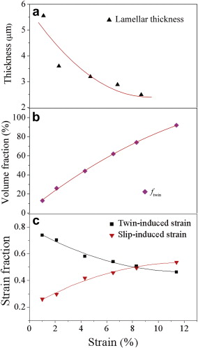 | Fig. 7. Microstructural statistical results: (a) lamellar thickness, (b) twin volume fraction ftwin, (c) twin/slip-induced strain rate of DPD AZ31 alloys with different strains. |
 | Fig. 8. (a) EBSD map of ε = 11.4% deformed sample, |
The strain accommodated by twinning can be calculated as follows [18]:
When twinning dominated the deformation of AZ31 alloy, a large number of twin lamellae were generated in grains due to the parallel twin structure, and lamellar thickness decreased with increasing plastic strain. Obviously, this microstructural evolution is directly related to twin nucleation and growth. Generally lamellar thickness decreases with the increase in the number of twin nucleation, or increases due to the growth of activated twins. A much higher stress is required for twin nucleation compared with twin growth [18]. So twin nucleation becomes more difficult, and the activated twins are easier to develop with further strain. At the early stage of twinning-dominated deformation ( ε < ∼4%), a lot of twins are activated, leading to a rapid decrease of the lamellar thickness with increasing strain. And the twin nucleation per grain is associated with grain area [23]. The growth of activated twins led to the decrease in the initial grain area, so the nucleation of new twins became more difficult with further strain. Meanwhile, the coalescence of growing twins led to the decrease in lamellar numbers. When deformation strain exceeds ∼4%, a little change of lamellar thickness with strain can be attributed to the fact that twin nucleation was restrained. Capolungo et al. [24] thought that twin thickening proceeded independently of slip in Mg. Here, it was thought that the twin growth would not be affected by dislocation slips.
Dislocation slips, replacing twinning, dominated the later deformation above ∼8%. The twin lamellar structure disappeared because the volume fraction of twins almost saturated at a value of ∼90%.
When the as-rolled AZ31 Mg alloy is subjected to dynamic plastic deformation perpendicular to the c-axis of hcp lattice, mostly one twin variant or a twin variant pair is activated in a grain, leading to a parallel twin lamellar structure. At the stage of twinning-dominated deformation ( ε < ∼8%), lamellar thickness decreases from 5.55 to 2.49 μm with increasing strain. The evolution of lamellar thickness during deformation is directly related to twin activity. At low strains ( ε < ∼4%), the positive nucleation of twins results in a rapid decrease in the lamellar thickness. When plastic strain is greater than ∼4%, the twin nucleation which is restrained due to the limited grain area and the growth of activated twins lead to a gradual decrease in the lamellar thickness. Dislocation slips dominate the later deformation beyond ∼8%. At this stage, twin lamellar structure disappears because the volume fraction of twins almost saturates at a value of ∼90%.
This work was supported by National Natural Science Foundation of China (Nos. , and ) and the Fundamental Research Funds for the Central Universities (No. ).
| 1. |
|
| 2. |
|
| 3. |
|
| 4. |
|
| 5. |
|
| 6. |
|
| 7. |
|
| 8. |
|
| 9. |
|
| 10. |
|
| 11. |
|
| 12. |
|
| 13. |
|
| 14. |
|
| 15. |
|
| 16. |
|
| 17. |
|
| 18. |
|
| 19. |
|
| 20. |
|
| 21. |
|
| 22. |
|
| 23. |
|
| 24. |
|