Fatigue Behaviors of a Ni-free ZrCuFeAlAg Bulk Metallic Glass in Simulated Body Fluid
[Wang Yimei, Liu Yan, Liu Lin*  ]
]
]
|
|


Fatigue behaviors of a biocompatible Ni-free Zr60.14Cu22.31Fe4.85Al9.7Ag3 Zr-based bulk metallic glass (BMG) have been studied under three-point-bending test in a simulated body fluid (SBF) at 37 °C and compared with those in air at room temperature (RT). The BMG shows a high fatigue limit of approximately 366 MPa in SBF, which was slightly lower than that in air (400 MPa). The fatigue cracks tended to initiate from the defects such as cast-pores, inclusions and corners of the samples and propagate in a similar path in SBF and in air. Three distinct regions, i.e. a crack-initiation region, a stable crack-growth region and an unstable fast-fracture region were clearly observed on the fatigue-fractured surface. Although pitting occurred at the defects where crack initiated, it does not affect significantly the fatigue life of the BMG, because the lifetime in the present BMG is mainly determined by crack propagation. The high corrosion-fatigue limit of the studied BMG results from its excellent corrosion resistance in SBF and intrinsically good toughness.
Zr-based bulk metallic glasses (BMGs) with atomic disordering structure have attracted much attention in recent years due to their potential for biomedical applications [1], [2], [3], [4], [5], [6] and [7]. The combination of low Young's modulus, high elasticity and strength, good bio-corrosion resistance and wear resistance makes the Zr-based BMGs very promising to be used as load-bearing implants, such as artificial joints and dental implants [8], [9] and [10]. However, these load-bearing implants usually suffer from cycle-loading in bio-corrosive environments, thus undergo the unavoidable fatigue deformation [11], [12] and [13]. Understanding of the fatigue behavior of the BMGs in bio-corrosive environment is crucial for the practical applications. As a matter of fact, extensive studies have been conducted on the fatigue properties of various Zr-based BMGs in air. It has been found that the BMGs exhibit a diversity of fatigue behavior and properties depending on the loading mode, material quality and surface conditions [14], [15], [16], [17], [18] and [19]. However, only very few work has been devoted to the effect of bio-corrosive environment on the fatigue behavior of the Zr-based BMGs [20] and [21]. Maruyama et al. [20] firstly studied the corrosion-fatigue behavior of Zr65Cu15Al10Ni10 BMG in a phosphate buffered saline (PBS) solution and found that the fatigue properties of the BMG in PBS were quite similar to those in air, as the defects originated from manufacturing process took the determinative effect on fatigue lifetime, thus covering up the corrosive effect. More recently, Huang et al. [21] investigated the corrosion-fatigue behavior of (Zr55Al10Ni5Cu30)99Y1 BMG, and reported that the fatigue limit decreased significantly in PBS, as compared to that in air, due to the occurrence of anodic dissolution on the specimens. However, the influence of physiological environments on the fatigue behavior and the failure mechanisms of the Zr-based BMGs are still far from being understood.
Recently, the author's group has developed a novel Ni-free BMG with the composition of Zr60.14Cu22.31Fe4.85Al9.7Ag3 (at.%). The BMG shows superior mechanical properties, including high compressive strength up to 1720 MPa, low Young's modulus of 82 GPa and high notch toughness of 94 MPa m1/2, as well as excellent biocompatibility, thus indicating a great potential to be used as the load-bearing implants [22]. However, for the possible medical applications, the evaluation of the fatigue properties of the BMG in physiological environments is essentially required. Therefore, in this work we have conducted a primary study on the bio-corrosion-fatigue behavior of this BMG in simulated body fluid (SBF) and compared the obtained result to that in air.
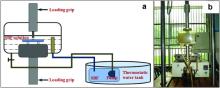
Alloy ingots with a nominal composition Zr60.14Cu22.31Fe4.85Al97Ag3 (at.%) were prepared from pure elemental metals of Zr, Cu, Fe, Al, Ag (purity > 99.5%) by arc-melting under a Ti gettered Ar atmosphere. The ingots were remelted at least five times to ensure the compositional homogeneity. Then rectangular plates with dimensions of 3.2 mm × 3.2 mm × 130 mm were fabricated by copper-mold sucking casting. Prior to the fatigue testing, X-ray diffraction (XRD, Philips' X'Pert PRO) and different scanning calorimetry (DSC, TA-Q2000) were performed to verify the amorphous structure of the prepared bars. The fatigue specimens with dimensions of 3 mm × 3 mm × 50 mm were then cut from the as-cast plates and all the four lateral sides of the specimens were mechanically ground and finally polished to mirror-finish in order to eliminate any possible effects of surface roughness or defects on the fatigue properties. Three-point-bending (3PB) fatigue test of the BMG (with a span of 30 mm) was carried out using a computer-controlled servo hydraulic-testing machine (QBS-50, made in China) under load control using a sinusoidal waveform and a load ratio of R = 0.2 (the ratio between minimum to maximum load) in air at room temperature (RT) and in simulated body fluids (SBF) at 37 °C, respectively. The composition of the SBF used was reported elsewhere [23]. A nominal frequency of 5 Hz was used at low fatigue cycles (<106), while a high frequency of 10 Hz was employed at high fatigue cycles (>106) [22] and [24]. Testing was continuously conducted until the samples failed or until the number of cycles reached 1 × 10⁷ cycles. Two to three samples were repeated at each load level for data reproducibility. Fig. 1 shows the schematic diagram (a) and photograph (b) of the setup for the corrosion-fatigue test used in this study, in which an acrylic chamber attachment was assembled on the fatigue testing machine. The sample was totally immersed in the SBF solution during the whole test. The SBF solution was kept at a constant temperature of 37 °C and was circulated by pumping. The morphology and composition of samples after fatigue fracture were examined by using a scanning electron microscope (SEM; FEI Quanta 200) coupled with the energy dispersive spectroscopy (EDS) system.
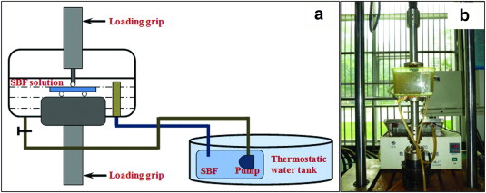 | Fig. 1. (a) A schematic diagram and (b) photograph of the setup for the corrosion-fatigue test used. |
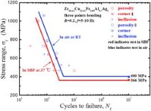
Fig. 2 shows the S– N curves of the Zr60.14Cu22.31Fe4.85Al9.7Ag3 BMG in air at RT and in SBF at 37 °C. It can be seen that the fatigue life ( Nf) at all applied stress ranges ( σr = σmax - σmin, where σmax and σmin indicate the maximum and minimum stress respectively in a loading cycle) in SBF were somehow less than, but still comparable to those in air. The corrosion-fatigue limit was approximately 366 MPa in SBF, which was slightly lower than the fatigue limit in air (400 MPa), representing about 8.5% reduction of the fatigue limit. Compared to the data reported previously in (Zr55Al10Ni5Cu30)99Y1 BMG (with 40% reduction) in similar testing condition [21], the present BMG seemed insensitive to the corrosion attack in SBF solution. In Fig. 2, the sites for crack initiation were also specified based on the SEM observation on the fractured surface of the BMG samples after fatigue failure, which show that the cracks mainly initiated at the corners or at the defects, such as porosities and crystalline inclusions, in both air and SBF conditions.
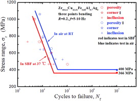 | Fig. 2. S– N curves for 3PB-fatigue tests of Zr60.14Cu22.31Fe4.85Al9.7Ag3 BMG in air at RT and in SBF at 37 °C at a frequency of 5–10 Hz and R = 0.2, in which the sites for crack initiation are also specified. |
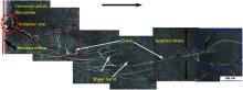
Fig. 3 displays a crack profile on the side surface of a specimen which was subjected to the fatigue test in SBF prior to failure in a stress range of 1000 MPa after 4800 cycles. It can be seen that the crack initially formed at a corrosion pit on the corner of the beam where stress concentration exists. Then the crack propagated generally along a perpendicular direction with respect to the tensile stress. It is interesting to note that the initiated crack tended to propagate microscopically in a zigzag path instead of cutting straight, as highlighted in the red boxes in Fig. 3, demonstrating that the fatigue crack propagation in the present case followed a mixed mode (i.e. Mode I and Mode II), which caused the dissipation of the plastic deformation energy and thus increased the resistance to crack propagation [25]. It is also noted that a number of shear bands appeared at both sides of the crack, indicating that severe plastic deformation occurred during crack propagation. It has been reported that the easy formation of shear bands at the crack tip would cause a high tendency for crack deflection [26] and thus change the loading mode [27]. In the crack tip zone (see the blue box at the right side in Fig. 3) one can see that a lot of shear bands formed in front of the tip, reflecting the plastic deformation caused by the intensive stress concentration ahead of the tip. It can be seen that cracks, as indicated by arrows, mainly propagated along the main shear bands.
 | Fig. 3. SEM fractograph of a crack profile on the side surface of a specimen which was subjected to the corrosion-fatigue test prior to failure in a stress range of 1000 MPa after 4800 cycles. The arrow above indicates the crack propagation direction. |
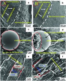
Fig. 4(a) and (b) shows the typical morphologies of the fracture surface for the samples tested in air (at σr = 653 MPa) and SBF (at σr = 600 MPa), respectively, with the lifetime around 23,000 cycles. The fractured surface morphologies were quite similar in air and in SBF, as characterized by three distinct regions, i.e. crack-initiation region, stable crack-growth region and fast-fracture region, as indicated in Fig. 4(a) and (b), respectively. In consistent to the previous work, the cracks usually initiated at the corner or the surface defects (such as inclusions or pores) [24] and [28]. Fig. 4(c) and (d) is the high magnification of the regions (i.e., regions A and B as shown in Fig. 4(a) and (b), respectively), which indicated that the crack initiated mainly from pores on the tensile side for the specimens tested in both air and SBF. It can also be seen that corrosion occurred at the sharp edge in the pore (see Fig. 4(d)), which is believed to play a role in accelerating crack initiation [29]. This can account for the slight reduction of the fatigue lifetime for the specimens tested in SBF as compared to that in air (see Fig. 2). Fig. 4(e) and (f) shows the amplified images from the stable crack propagation regions for the specimens tested in both air and SBF, respectively. The features of crack propagation were almost similar in the two samples and were characterized by regular coarse striations with spacing of about 4.5 μm and fine striations with spacing of about 0.5 μm. The boundaries of coarse striations in SBF were not as clear as that in air, probably due to the corrosive effect in SBF. The coarse striation spacing was about 9 times wider than the fine one, which was similar to the results reported by Wang et al. [30]. Actually, the similar morphology for fatigue fracture surface in the stable crack propagation region was also observed in other BMG systems [21], [30], [31] and [32]. It is argued that fine striations correspond to the fatigue cycling, i.e. one cycle generates one striation, while the coarse striations are considered to be associated with the shear banding in the vicinity of the crack tip [30] and [31]. This should be the same case in the present study. It is noted that the fatigue crack propagation behavior of the BMG seemed not affected significantly by corrosion attack in SBF solution, as the fracture morphologies and the striation spacing were almost the same in air and in SBF. In addition, the corresponding fatigue fracture toughness was also calculated using Newman's theory [33], yielding a value of 32–50 MPa m1/2 and 30–45 MPa m1/2 for BMGs tested in air and SBF, respectively. They were also very similar in the two testing conditions, demonstrating further minimal influence of SBF solution on the fatigue properties of the BMG. The fatigue toughness was much higher than other Zr-based BMGs [18], indicating that the present Zr60.14Cu22.31Fe4.85Al9.7Ag3 BMG, even in SBF environment retained good resistance to crack propagation.
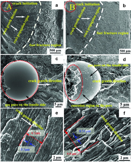 | Fig. 4. SEM fractographs of the typical fracture surface of the specimens failed in air and in SBF. (a) and (b) Overall fatigue morphology in air and in SBF, respectively; (c) and (d) crack initiated from the casting pores on the tensile surface in air and in SBF, respectively; (e) and (f) coarse and fine striations in crack-growth regions in air and in SBF, respectively. Corresponding spacing is measured. |
Different from the most high-strength crystalline materials, in which persistent-slip bands, deformation bands, twinning and grain boundaries are usually considered as the preferential sites for the nucleation of fatigue cracks, the fatigue cracks in the BMGs usually initiated at the defects, such as casting pores, inclusions and stress concentration at the corners, or even surface scratches [20], [24] and [28]. This is actually what happened in the present study (see Fig. 2). It have been reported that the fatigue lifetime of BMGs is mainly determined by the fatigue crack-growth stage, while crack initiation takes up only 25% or even less of the total fatigue life [24]. Though pitting mostly occurred at those defects ( Fig. 4(d)) may promote the crack initiation, the fatigue lifetime and fatigue limit, determined by cracks propagation seemed insensitive to the environmental attack in SBF, and still kept a high level with respect to those in air. In addition, the crack propagation is very susceptible to the load ratio R, the crack-growth rate generally increases with increasing loading ratio [26], [34] and [35], therefore, it is expected that the fatigue limit of the Zr60.14Cu22.31Fe4.85Al9.7Ag3 BMG could be even higher if R = 0.1 was chosen.
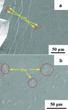
Regarding the reasons for the excellent corrosion-fatigue properties of Zr60.14Cu22.31Fe4.85Al9.7Ag3 BMG in this study, it is proposed that the excellent corrosion resistance in SBF and intrinsically good toughness contribute to the high fatigue limit of BMG. Fig. 5(a) shows the SEM morphology of the side surface of a fatigue specimen in the stress range of 600 MPa after about 28,000 cycles (tested for about 1.5 h) in SBF at 37 °C, which shows almost free of pits on the out-surface of the BMG sample tested. Only a few small pits formed even after immersion in SBF for 30 days (see Fig. 5(b)), demonstrating a good corrosion resistance of the BMG in SBF, which is attributed to the formation of passive film with the enrichment of ZrO2 and Al2O3 [22]. The experimental results indicated that the fatigue crack mainly initiated at surface defects, e.g., pores and inclusions or corners of the samples both in air and in SBF solution. Although pitting usually occurs at these defects, it cannot play a determined role in fatigue properties due to the small size of pits (less than 10 μm) as compared to size of the defects (see Fig. 5). In addition, the high fracture toughness with K = 30–45 MPa m1/2 may also contribute to the good corrosion-fatigue properties.
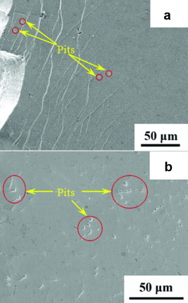 | Fig. 5. SEM fractographs of (a) side surface of fatigue specimen failure at stress range of 600 MPa after about 28,000 cycles in SBF at 37 °C and (b) surface of specimen immersed in SBF for 30 days. |
In this study, the fatigue behaviors of a Ni-free ZrCuFeAlAg BMG were investigated in air at room temperature and in simulated body fluid (SBF) at 37 °C under three-point-bending test. The fatigue endurance limit of the BMG was approximately 366 MPa in SBF, which was slightly lower than that in air (400 MPa). The fatigue cracks initiated mainly from the defects of the specimens, such as casting pores, inclusions and corners, and propagate microscopically in a zigzag path along the main shear bands both in air and in SBF. The fatigue-fractured surfaces were very similar in two testing conditions with distinct three regions: i.e. crack initiation, stable crack propagation region and fast-fracture region. Though pitting mostly occurred at the defects in SBF, which may promote the crack initiation, the fatigue lifetime and fatigue limit, determined by cracks propagation, still kept a high level with respect to those in air. The excellent corrosion resistance in SBF and high toughness can account for the good corrosion-fatigue properties of the BMG.
References
This work was financially supported by the National Nature Science Foundation of China (Grant Nos. 51071072 and 51271081). The authors are grateful to the Analytical and Testing Center, Huazhong University of Science and Technology for technical assistance.
| 1. |
|
| 2. |
|
| 3. |
|
| 4. |
|
| 5. |
|
| 6. |
|
| 7. |
|
| 8. |
|
| 9. |
|
| 10. |
|
| 11. |
|
| 12. |
|
| 13. |
|
| 14. |
|
| 15. |
|
| 16. |
|
| 17. |
|
| 18. |
|
| 19. |
|
| 20. |
|
| 21. |
|
| 22. |
|
| 23. |
|
| 24. |
|
| 25. |
|
| 26. |
|
| 27. |
|
| 28. |
|
| 29. |
|
| 30. |
|
| 31. |
|
| 32. |
|
| 33. |
|
| 34. |
|
| 35. |
|