

1. Introduction
High-entropy alloys (HEAs), consisting of five or more elements with equiatomic or near-equiatomic concentration, are widely investigated due to their exceptional mechanical properties, e.g., high strength and hardness [[1], [2], [3], [4]]. In general, the experimental results demonstrate that HEAs tend to form simple solid-solution structures or multi-phase structures due to their high mixing entropy [[5], [6], [7]]. Recently, the high-entropy bulk metallic glasses have been developed by the rapid cooling method [[8], [9], [10], [11], [12]]. The HE-BMGs, the combination of HEAs and bulk metallic glasses (BMGs), which have both strong topological and chemical disorder, show some unique or remarkably improved properties, compared with the normal BMGs or HEAs [13,14].
To improve the mechanical properties in BMG composites, the amorphous-crystalline multilayered structures are fabricated by the magnetron sputter deposition of alternating layers of various metals [[1], [2], [3], [4], [5], [6], [7], [8], [9], [10], [11], [12], [13], [14], [15], [16], [17]]. By a controlled growth of crystalline and amorphous phases, the deformation behaviors are systematically studied [[18], [19], [20]]. For example, in the amorphous/nanocrystalline (e.g., CuZr/Cu) composite, a multilayer structure can suppress the formation of shear bands and enable plastic co-deformation of the two phases [[21], [22], [23], [24]]. The effects of layer thickness and sample size on the deformation behavior of crystalline/amorphous Cu/CuZr composites under tension loading are investigated using a molecular dynamics (MD) simulation method. The peak stress reaches a plateau when the crystal layer thickness is larger than 5 nm [21]. The effect of grain-boundary characteristics on the atomistic mechanisms of yielding and plastic deformation behavior is constructed. It demonstrates a transition of the deformation mode from the localized to homogeneous-like deformation by tailoring the relative volume fraction of the Cu layers [22]. Using a systematic experiment and MD simulation, a transition of deformation modes from shear banding to co-deformation subject to nanoindentation was revealed by a systematic experimental study of the amorphous/crystalline composite [23,24]. In those investigations, the crystalline and amorphous layers usually remained of equal thickness, and thus, the transition of deformation behaviors may emerge from the length-scale effect of both amorphous and crystalline phases [25,26]. Recently, the amorphous/crystalline HEA FeCrCoNi has been successfully prepared by the high-pressure torsion (see Fig. 1(a)) [8]. More recently, the HEA coated with the amorphous films represents the high yielding strength and ultimate tensile strength attributed to the limitation of the dislocation nucleation and mobility by the back stress and repulsive image stress at the interface [[27], [28], [29]]. The structural hierarchy of AlCoCrCuFeNi HEA can been obtained by controlling cooling rates, and the mechanical behavior of HEA composite is optimized to maximize high strength [30]. However, up to now, little work has been conducted concerning the influence of the amorphous layer thickness on the mechanical properties in the amorphous/crystalline HEA composite.
Fig. 1.
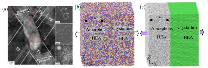
Fig. 1.
(a) The amorphous/crystalline HEA FeCoCrNi composite prepared by high-pressure torsion from the experiment [8] and (b, c) the tension model of the amorphous/crystalline HEA structures ( 


In the present work, the deformation behavior in the amorphous/crystalline HEA FeCrCoNi composite of varying amorphous layer thicknesses is investigated using the MD simulation method. The structural/interfacial evolution, shear strain, and stress have been studied to reveal the thickness effect of the amorphous HEA layer on the mechanical properties.
2. Simulation model and method
Fig. 1(b) and (c) shows the tension simulations of amorphous/crystalline HEA FeCrCoNi structures. This model includes the amorphous HEA and crystalline HEA. The dimension of the sample is 15.5 nm × 15.2 nm × 16.1 nm. To investigate the effect of size on the tensile deformation in the amorphous/crystalline HEA composite, the various amorphous HEA layer thicknesses can range from 0 to 15.5 nm. The amorphous/crystalline HEA FeCoCrNi is randomly distributed with Fe, Co, Cr, and Ni atoms. To obtain the amorphous HEA model, it is melted at 2500 K in the isobaric-isothermal ensemble (NPT) first, then quenched from 2500 K to 300 K at a cooling rate of 10 K/ps [[21], [22], [23], [24],30]. According to the experiment [8], the crystallographic orientation of the crystalline HEA layer is set as [011] along the x-axis, [[1], [2], [3], [4], [5], [6], [7], [8], [9], [10], [11]] along the y-axis, and [21,1] along the z-axis. Periodic boundary conditions are applied along x, y, and z directions. The embedded atom method (EAM) potential is widely used to study the solidification, microstructure evolution, and plastic deformation driven by tension [[30], [31], [32], [33], [34]]. Using the current EAM potential, some works have studied the microstructure evolution, mechanical properties, and strengthening mechanism in single crystal HEA [34], dual-phase HEA [6], nanocrystalline HEA [35] and amorphous HEA [36,37].
The initial temperature of MD simulations in the amorphous/crystalline HEA FeCoCrNi composite is 300 K. Before the tension, the sample is first subjected to the energy minimization using the conjugate gradient method [6,[34], [35], [36]], and then all relaxed to obtain an equilibrium state. The constant strain rate of 1 × 10⁸ s-1 is applied along the x-direction [[34], [35], [36]]. A time step is 1 fs in all MD simulations, using the large-scale atomic/molecular massively-parallel simulator (LAMMPS) [38]. The microstructural evolution is presented via the Ovito software [39]. The common neighbor analysis (CNA) is used to identify the microstructure after deformation, where red atoms represent the stacking fault, green atoms mean the face-centered cubic (FCC) structure, and the white atoms are the dislocation core and interface structure as well as amorphous structure.
3. Results
According to the previous work [[21], [22], [23]], the layer thickness of a crystal structure plays a key role in the mechanical properties and deformation mechanisms in crystalline/amorphous composites. The stress-strain curves of the amorphous/crystalline HEA FeCoCrNi composite with different amorphous layer thicknesses are presented in Fig. 2(a), where the thicknesses of the amorphous HEA layer are 0 nm, 3 nm, 6 nm, 9 nm, 12 nm, and 15.5 nm. The corresponding volume fractions between the amorphous HEA layer and composite are 0%, 19.4%, 38.7%, 58.1%, 77.4%, and 100%. Apart from the amorphous HEA, the deformation of the amorphous/crystalline HEA with varying thicknesses suffers with the elastic stage, yielding stage, softening stage, and hardening stage (Fig. 2(a)). In the amorphous/crystalline HEA composite, the crystalline HEA has the high strength, followed by the amorphous/crystal structure, and finally amorphous structure. This result agrees with the report in crystalline Cu/amorphous Cu50Zr50 composites, where the strength of the crystalline Cu is higher than that of the amorphous Cu50Zr50 [21]. Moreover, with the increasing thickness of the HE-BMG layer, the strength of the HE-BMG/crystalline sample reduces, in good agreement with the experiment results in the amorphous Cu45Zr55/crystalline Cu [23]. As can be found, the single crystal HEA samples possess the high yielding strength, compared to their amorphous counterparts. The similar results are observed in the stress-strain curves of amorphous/crystalline Au nanowires, Mg alloys, CuAg alloys, and CuZr alloys [[40], [41], [42], [43]]. This trend is attributed to the strong size effect in the single crystal sample [44]. However, the traditional bulk alloys present coarse-grained/fine-grained structures, which have a low strength compared to their amorphous counterparts owing to the nucleation of voids or cracks from grain boundary, and grain boundary sliding at a low critical threshold stress [[45], [46], [47]].
Fig. 2.

Fig. 2.
Stress vs. strain in the amorphous, crystal, and amorphous/crystal HEA at different thicknesses of the amorphous HEA layer (a) and yielding strength and strain at different thicknesses of the amorphous HEA layers (b).
Using the mixed principle, the flow stress of multilayers can be estimated by $\sigma ={{\sigma }_{\text{a}}}{{t}_{\text{a}}}/\left( {{t}_{\text{a}}}+{{t}_{\text{c}}} \right)+{{\sigma }_{\text{c}}}{{t}_{\text{c}}}/\left( {{t}_{\text{a}}}+{{t}_{\text{c}}} \right)$ [23], where ${{\sigma }_{\text{a}}}$ and ${{\sigma }_{\text{c}}}$ represent the flow stresses of the amorphous and crystalline HEA, respectively. ${{t}_{\text{a}}}$ and ${{t}_{\text{c}}}$ represent the thicknesses of the amorphous and crystalline HEA layers, respectively. Here, the flow stress decreases with the increasing thickness of the amorphous HEA, consistent with the result of Fig. 2(a). It can be noted that the stress significantly drops in the sample with the small thickness of the amorphous HEA layer after yielding (Fig. 2(a)). On the other hand, the yielding strain increases with the decreasing thickness of the amorphous HEA layer (Fig. 2(b)), indicating the softening in advance. Hence, the thickness of the amorphous HEA layer plays a critical role in the overall mechanical response under tensile deformation.
To reveal the underlying deformation mechanism of the amorphous/crystal HEA composite considering the effect of the amorphous HEA layer, the atomic structures of amorphous/crystal HEA composites at the tensile strain of 20% are presented in Fig. 3. The nucleation of the Shockley partial dislocation could occur at the crystalline-amorphous interface, and then Shockley partial dislocations are absorbed at the opposite interface in Fig. 3(b-g). The corresponding dislocation densities are 7.28 × 10¹⁷ m-2, 6.68 × 10¹⁷ m-2, 5.18 × 10¹⁷ m-2, 9.62 × 10¹⁷ m-2, 1.35 × 10¹⁷ m-2, and 4.32 × 10¹⁷ m-2 in Fig. 3, in addition to the pure amorphous HEA. With the increasing thickness of the amorphous HEA layer, the dislocation density dynamically fluctuates, exhibiting different degrees of plastic deformation in the crystalline layer. It is confirmed that the deformation behavior of the crystal layer has a good correlation to the dislocation density [48,49], and depends on the thickness of the amorphous HEA layer. By comparing Fig. 2, Fig. 3, the high strength mainly comes from the contribution of the crystalline HEA layer through the dislocation hardening mechanism, and the nucleation and slip of dislocations in the crystalline HEA layer further activate plasticity in the amorphous HEA layer [[40], [41], [42], [43]]. Especially, the deformation twins occur at the interface (Fig. 3, Fig. 4), which strongly affects the mechanical properties of the amorphous/crystal HEA composite [8,30]. Moreover, the dislocation nucleation leads to the non-smooth interface structure (Fig. 5). Here, for different thicknesses of the amorphous HEA layers, the interface morphology is presented in Fig. 5(a-f), and the atomic displacement is shown in Fig. 5(g-l), to reveal the fluctuation of the interface morphology on the deformation behavior. The red atom means the high atomic displacement, and the blue atom indicates the low atomic displacement. As a result, the strip texture generates in the non-smooth interface, which provides nucleation sites for the shear-band embryo (Fig. 6).
Fig. 3.

Fig. 3.
The structural evolution at the strain of 20% and different materials: the crystalline HEA (a), the amorphous HEA layer with 3 nm (b), the amorphous HEA layer with 6 nm (c), the amorphous HEA layer with 9 nm (d), the amorphous HEA layer with 12 nm (e), and the amorphous HEA (f) at a strain of 20%. Dotted lines represent interfaces.
Fig. 4.

Fig. 4.
The deformation twins at the strain of 20 % and different amorphous HEA layers: (a, b) 3 nm; (c, d) 6 nm. This region is marked by the blue circles in
Fig. 5.

Fig. 5.
The interface morphology in the strain of 20% and different amorphous HEA layers: (a, e) amorphous HEA layer with 3 nm; (b, f) amorphous HEA layer with 6 nm; (c, g) amorphous HEA layer with 9 nm; (d, h) amorphous HEA layer with 12 nm. (a-d) represent the surface morphology of the interface, and (e-h) represent the atom displacement from the interface.
Fig. 6.

Fig. 6.
The shear strain distribution at the strain of 20% and different materials: the crystalline HEA (a), amorphous HEA layer with 3 nm (b), amorphous HEA layer with 6 nm (c), amorphous HEA layer with 9 nm (d), amorphous HEA layer with 12 nm (e), and amorphous HEA (f). Dotted lines represent interfaces.
4. Discussion
In order to obtain the deep understanding of the influence of microstructures on the deformation behavior [[21], [22], [23]], the atomic shear strain of the amorphous/crystal HEA composites is calculated after the tensile deformation. Fig. 6(a-d) displays the distribution of the atomic shear strain after the deformation at the total strain of 20%. The shear strain is computed by determining the deformation gradient tensor from the initial and current atomic positions. The red atom means a high shear strain, and the blue atom indicates a low shear strain. The obvious main shear bands are observed in the crystalline layer, and a large number of tiny shear bands occur in the amorphous HEA. Moreover, the high shear strain in the amorphous HEA layer is concentrated in the interface region. The shear band does not penetrate the interface from the crystalline to amorphous HEAs, which is different with the previous report about the shear band across the crystal and amorphous structure in the multilayer amorphous Cu50Zr50/Cu nanolaminated composites [22]. The dislocation nucleation induces the formation of shear bands, which could be proved in the high strain located at the contact interface between the dislocation and amorphous HEA (Fig. 6). Hence, the slip mechanism is found in the amorphous/crystal HEA composites, to enhance the plastic ability of the amorphous HEA.
The local stress concentration plays a decisive role in the deformation behavior, leading to controlled mechanical properties. Here, the distribution of the stress along the x direction is shown in Fig. 7. The red atom means the high tensile stress, the blue atom indicates the high compressive stress, and the green atom represents the low or free stress. Compared to the crystalline HEA layer, the amorphous HEA layer presents a more complex stress distribution, where the local high tensile and compressive stresses alternately appear in the loading plane. Meanwhile, the crystalline HEA shows the relatively stable and low peak in the stress distribution. This trend is due to that the amorphous HEA has the random distribution of different elements with various atomic radii [[1], [2], [3], [4], [5], [6]]. The shear bands are very difficult to pass through the interface, due to the complex stress fields. Furthermore, the local stress gradient drives the deformation behavior, to control the mechanical properties, especially the softening effect. Hence, the fluctuation of the stress from the tensile to compressive stresses in the range of several Ångstrom scales along the interface, controls the slip of dislocations in the crystalline layer and the formation of shear bands in the amorphous HEA layer. This trend leads to a more homogeneous redistribution of plastic deformation (Fig. 3, Fig. 4, Fig. 5, Fig. 6, Fig. 7). A comparison of Fig. 6, Fig. 7 shows the universal phenomenon of the local yield in the amorphous HEA layer due to the different atomic bond strengths. It can govern the interface properties, which control both the thickness-dependent global yield strength and strain hardening of the amorphous/crystal HEA composite.
Fig. 7.

Fig. 7.
The stress distribution at the strain of 20% and different materials: the crystalline HEA (a), amorphous HEA layer with 3 nm (b), amorphous HEA layer with 6 nm (c), amorphous HEA layer with 9 nm (d), amorphous HEA layer with 12 nm (e), and amorphous HEA (f). Dotted line represents the interface.
To characterize the local structure of the deformed HEA, the Voronoi polyhedron method (VPM) is employed to identify the structure according to the previous study [[50], [51], [52]]. The VP can be indexed as < n3, n4, n5, n6, …, ni>, where ni represents the number of i-edge faces on the VP [[50], [51], [52]]. The majority of VPs can be denoted by a 4-integer index < n3, n4, n5, n6> [50]. In addition, the vertex is ignored if the number of atoms in the VP is less than 1% of the total. Fig. 8 shows the distribution and proportion of VPs in deformed HEA. When the amorphous HEA layer is larger than 9 nm, the top three VPs are <0, 1, 10, 2 > , <0, 3, 6, 4> and <0, 0, 12, 0> before the deformation (Fig. 8(a)), and after the deformation (Fig. 8(b)). When the amorphous HEA layer is lower than 6 nm, <0, 4, 6, 3> and <0, 5, 6, 2> in the top two VPs take place. With increasing amorphous HEA layer, the VPs of <0, 3, 8, 2>, <0, 4, 4, 6>, <0, 4, 6, 2>, <0, 4, 6, 3>, <0, 4, 6, 4>, <0, 5, 4, 4>, <0, 5, 6, 1>, <0, 5, 6, 2>, <0, 5, 6, 3>, <0, 6, 2, 5>, <0, 6, 4, 2>, <0, 6, 4, 3>, <0, 6, 6, 1>, <0, 7, 4, 1) increase, and the VPs of <0, 1, 10, 2>, <0, 1, 10, 3>, <0, 1, 10, 4>, <0, 2, 8, 2>, <0, 2, 8, 3>, <0, 2, 8, 4>, <0, 2, 8, 5>, <0, 3, 6, 4>, <0, 3, 6, 5> decrease. When the amorphous HEA layer decreases to 3 nm, new VPs of <0, 6, 6, 1> and <0, 7, 4, 1> occur. Compared to VPs in the deformed HEA before the deformation, a similar distribution and proportion of VPs can be observed in the deformed HEA after the deformation (Fig. 8(b)), in addition to VPs of <0, 4, 4, 6>, <0, 5, 4, 4>, <0, 4, 4, 6>, and <0, 6, 2, 5>. Moreover, these VPs only exit in a deformed HEA, and the VPs of <0, 1, 10, 4>, <0, 3, 8, 2>, <0, 5, 6, 1>, <0, 5, 6, 3>, and <0, 7, 4, 1> only exit in an undeformed HEA. Thus, the VP evolution depends on the thickness of the amorphous HEA layer, and then regulates the mechanical properties.
Fig. 8.

Fig. 8.
Distribution and proportion of major VPs before deformation (a) and after deformation (b) at different amorphous HEA layers.
5. Conclusion
In the current work, the deformation behaviors and mechanical properties in amorphous/crystal HEA composites are investigated by means of MD simulations. The effects of the amorphous HEA layer thickness on the tensile deformation behavior are systematically studied. The dislocation nucleation in the crystal HEA layers and the formation of multiple embryonic shear bands in the amorphous HEA layers take place after plastic deformation. The strength of amorphous/crystal HEA composites reduces with increasing the thickness of the amorphous layer. This trend agrees with not only the previous experimental results in the amorphous Cu45Zr55/crystalline Cu, but also the mixed principle of a simple composite average. Furthermore, the softening stress and the yielding strain increase, as the thickness of the amorphous HEA layer decreases. The origin of the high plasticity is attributed to the enhanced redistribution of plasticity, by the coupled interaction between the crystal plasticity, and the glassy plasticity at the nanoscale. This deformation mechanism results in the high yielding strength in the nanolaminated composites. Moreover, tailoring the thickness of the amorphous layers would be an effective way, for tuning the plasticity of nanolaminated composites. The results provide the fundamental understanding the underlying atomistic mechanisms of yielding and tunable plasticity, which guide the design of the amorphous HEA with the high strength and good plasticity.
Acknowledgements
This work was supported financially by the Foundation for Innovative Research Groups of the National Natural Science Foundation of China (No. 51621004), the National Natural Science Foundation of China (Nos. 51871092, 11772122, and 51771233), the State Key Laboratory of Advanced Design and Manufacturing for Vehicle Body (No. 71865015), the Fundamental Research Funds for the Central Universities (No. 531107051151) and the National Key Research and Development Program of China (Nos. 2016YFB0700300 and 2016YFB1100103). P.K. Liaw very much appreciates the support of the U.S. Army Research Office Project (Nos. W911NF-13-1-0438 and W911NF-19-2-0049) with the program managers, Drs. M.P. Bakas, S.N. Mathaudhu, and D.M. Stepp. P.K. Liaw thanks the support from the National Science Foundation (Nos. DMR-1611180 and 1809640) with the program directors, Drs. J. Yang, J.G. Shiflet, and D. Farkas.
Reference
DOI
URL
PMID
[Cited within: 4]

Realizing improved strength-ductility synergy in eutectic alloys acting as in situ composite materials remains a challenge in conventional eutectic systems, which is why eutectic high-entropy alloys (EHEAs), a newly-emerging multi-principal-element eutectic category, may offer wider in situ composite possibilities. Here, we use an AlCoCrFeNi2.1 EHEA to engineer an ultrafine-grained duplex microstructure that deliberately inherits its composite lamellar nature by tailored thermo-mechanical processing to achieve property combinations which are not accessible to previously-reported reinforcement methodologies. The as-prepared samples exhibit hierarchically-structural heterogeneity due to phase decomposition, and the improved mechanical response during deformation is attributed to both a two-hierarchical constraint effect and a self-generated microcrack-arresting mechanism. This work provides a pathway for strengthening eutectic alloys and widens the design toolbox for high-performance materials based upon EHEAs.
DOI
URL
PMID
[Cited within: 1]
Two kinds of crystalline/amorphous nanolaminates (C/ANLs), i.e., Ag/Cu-Zr and Mo/Cu-Zr, with a wide range of modulation ratios eta (thickness ratio of the amorphous layer to the crystalline layer) from 0.1 up to 9.0 were, respectively, prepared using magnetron sputtering. The hardness and the strain rate sensitivity m were measured for comparison through nanoindentation testing. The mechanical properties displayed a strong eta-dependence, which was tuned by the crystalline phases. With the increase of eta, the hardness increased in the Ag/Cu-Zr nanolaminates while it decreased in the Mo/Cu-Zr ones. However, the two C/ANLs showed similar variations in m that was reduced gradually from positive values at small eta to negative values at large eta. Microstructural examination demonstrated that the amorphous Cu-Zr layers in both the C/ANLs showed a deformation-induced crystallization (DIC) phenomenon within the nanoindentation deformation zone. The DIC was highly dependent on eta and became more intense in the Mo/Cu-Zr than in the Ag/Cu-Zr C/ANLs. The eta- and constituent-dependent DIC behaviors were rationalized in light of the stress field applied on the amorphous layers that is sensitive to both the amorphous layer thickness and the crystalline constituents. This DIC-induced negative m in amorphous layers competed with the positive m in crystalline layers, leading to a negative-to-positive change in m on reducing eta. The underlying deformation mechanism was revealed to be the cooperation between dislocation activities in the crystalline layers and shear transformation zone motions in the amorphous layers. Furthermore, a modified mechanistic model was utilized to quantitatively describe the eta-dependent hardness at different crystalline constituents.
DOI
URL
PMID
[Cited within: 2]
Icosahedral order has been suggested as the prevalent atomic motif of supercooled liquids and metallic glasses for more than half a century, because the icosahedron is highly close-packed but is difficult to grow, owing to structure frustration and the lack of translational periodicity. By means of angstrom-beam electron diffraction of single icosahedra, we report experimental observation of local icosahedral order in metallic glasses. All the detected icosahedra were found to be distorted with partially face-centered cubic symmetry, presenting compelling evidence on geometric frustration of local icosahedral order in metallic glasses.

 WeChat