

1. Introduction
Aluminum alloys are widely used in automotive industries due to their light weight, recyclability and environmentally friendliness [[1], [2], [3]]. Hypoeutectic Al-Si casting alloys with high specific strength and excellent casting properties are extensively applied in the automotive parts like automobile hub, steering wheel and dashboard [2,[4], [5], [6]]. As one of the most popular manufacturing processes for aluminium alloys, high pressure die casting (HPDC) process is widely used because of high production efficiency, high quality assurance and considerable economic benefits [7,8]. Employing the vacuum-assist HPDC, Li et al. [9] found samples exhibited ∼90% lower porosity than those of conventional HPDC samples with an improvement of ∼20% higher strength, double elongation and treble fatigue life achieved.
In the process of die-casting, the solidification contains two stages including slow-shot stage and fast-shot stage [10]. The first stage starts in the shot sleeve where the plunger pushes the melt forward. During the slow-shot stage, the temperature of metal liquid near the chamber wall dropped between solidus and liquidus. Externally solidified crystals (ESCs) and Fe-rich phase precipitated from liquid along chamber wall, growing into coarse microstructure rapidly and remaining in the solidified casting ultimately. During the fast-shot stage, the melt was injected into the die cavity with a filling time of less than 20 ms [11]. After filling, the whole casting became solidified in about several seconds because of fast heat transfer between the melt and die wall (heat transfer coefficient was estimated to be ∼104-105 W·m-2 K-1) [12]. A typical microstructure of HPDC hypoeutectic Al-Si alloys comprised of externally solidified crystals (ESCs), Al grains and eutectic. ESCs with a large size over 10 μm formed in the shot sleeve while Al grains with a smaller size less than 5 μm formed in die cavity. Both ESCs and Al grains belonged to primary α-Al.
Employing the Fe element in the spray agent can help removing the casting part from the die. However, Fe-rich phases doping in aluminum alloy severely damage mechanical properties of the casting. Zhang et al. [13] summarized the detrimental effect of Fe-rich phases on aluminum alloys and found brittle platelet β Fe-rich phases lowered the mechanical properties of casting. Using 3-D reconstruction models, Dinnis et al. [14] found the plate-like Fe-rich phases (β-Al5FeSi) and Chinese script-type Fe-rich phases (α-Al15(Mn, Fe)3Si2) were common in as-cast Al-Si alloys. Li et al. [15] found that, with Mn element addition, partial plate-like β-Al5FeSi transformed into Chinese script-type α-Al15(Mn, Fe)3Si2 with a significant improvement on mechanical properties. Similarly, Co, Cr and Ni could also change the morphology of Fe-rich phases and reduce the harmful influence of β Fe-rich phases [16,17]. The size and morphology of Fe-rich phases also varied in different cooling rates. Becker et al. [18] found δ phase changed into β phase and the size increased rapidly with the decrease of cooling rate. Samuel et al. [19] discovered the effect of alloying elements on Fe-rich phases was weakened at slow cooling rate. Gorny et al. [20] found incomplete peritectic reactions (Al13Fe4+Liquid→Al8SiFe2, Al8SiFe2+Liquid→Al9Fe2Si2) happened and three kind of Fe-rich phases was present under high cooling rate. Table 1 shows the summary of Fe-rich phases in hypoeutectic Al-Si alloys. As Becker [18] mentioned, the characteristic of Fe-rich phases largely depended on solidification rate and the chemical composition. Fe-rich phases have been extensively reported, but studies on Fe-rich phases in HPDC are rather limited.
Table 1 Summary of Fe-rich phases in hypoeutectic Al-Si alloys.
| Phase | Crystal structure | Space group | Lattice constant | Morphology | Nucleation position | Reference |
|---|---|---|---|---|---|---|
| β-Al5FeSi | Monoclinic | A12/a1, I41/acd | a = 0.616 b = 0.618 c = 2.081 β = 90.42 | Plate-shaped | High Fe content and slow cooling speed | [18,21] |
| δ-Al4FeSi2 | Orthorhombic | I4/mcm | a = 0.615 b = 0.615 c = 0.952 | Needle-like shaped | Relatively high cooling speed | [18,22] |
| α-Al8Fe2Si | Hexagonal | P63/mmc | a = 1.24 c = 2.63 | Polyhedral-shaped | High Fe content and slow cooling speed | [18,23] |
| α-Al15Fe3Si2 | Cubic | Im3¯ | a = 1.253 | Polyhedral-shaped, Chinese script-type | High cooling speed and Mn addition | [14,18,24] |
In this study, Fe-rich phases in a high-pressure die-cast hypoeutectic Al-Si alloy were characterized. Particular attention was focused on morphology and their effects on fracture of a HPDC AlSi10MnMg alloy. Furthermore, by using the synchrotron X-ray tomography technique, Fe-rich phases with different morphologies were extracted and investigated.
2. Experiment
A commercial hypoeutectic AlSi10MnMg was used and the chemical composition was listed in Table 2. As a widely used alloy in auto parts, AlSi10MnMg has attracted great attention in recent years. A TOYO BD-350V5 cold chamber die casting machine was employed in the experiment. Fig. 1(a) shows the configuration of the HPDC casting, which comprised two testing bars and four plates. Another HPDC casting including three tensile testing bars and one plate used in this experiment could be found in [7,10]. Fig. 1(b) shows the positions where the samples were extracted. Samples for optical microscope (OM), scanning electron microscope (SEM), transmission electron microscopy (TEM) and electron probe micro-analyzer (EPMA) analysis were extracted from the center of standard testing bar. Samples for synchrotron X-ray tomography was extracted along the radial direction with a size of ϕ1 × 5 mm. Fig. 1(c) and (d) show the tensile testing plate and in-situ testing specimen extracted from the plate (see Fig. 1(a)). Table 3 shows the key processing parameters adopted in the experiment. A vacuum system, similar as that in [9], was employed in the experiment.
Table 2 The chemical composition of the AlSi10MnMg hypoeutectic Al-Si alloy (wt.%).
| Si | Fe | Cu | Mn | Mg | Zn | V | Ti | Sr | Al |
|---|---|---|---|---|---|---|---|---|---|
| 9.5-11.5 | < 0.15 | < 0.03 | 0.5-0.8 | 0.1-0.5 | < 0.07 | < 0.07 | 0.04-0.15 | 0.01-0.025 | Bal. |

Fig. 1.
The configuration of (a) HPDC casting including two tensile test bars and four plates; (b) tensile test bar and sample extraction locations for OM, SEM, TEM, EPMA and synchrotron X-ray tomography; (c) tensile test plate and (d) in-situ tensile test specimen.
Table 3 The key processing parameters in HPDC.
| Melting temperature (°C) | Initial mold temperature (°C) | Slow-shot speed (m/s) | Vacuum condition |
|---|---|---|---|
| 680 | 120 | 0.05, 0.4 | On |
The metallographic samples were mounted by epoxy resin, grinded using SiC papers (400-2000 grit size) and then polished with ethyl alcohol based colloidal silica suspension (0.1 μm). Ultrasound cleaning was applied to polish the specimen. The specimen surface was then etched by a 0.5 vol%HF for 30 s to observe the Fe-rich phases using SEM. EPMA (JXA-8530 F) was used to obtain the element distribution. For TEM observation, sample was mechanically ground to ∼300 μm and then milled by ion beam (Ar+) with Gatan 691 ion milling machine after dimpling. The synchrotron X-ray tomography experiment was performed at Shanghai Synchrotron Radiation Facility (SSRF) using the BL13W1 beamline. X-ray imaging parameters in the experiment stayed the same as in [25], unless stated otherwise. After scanning, a total of 720 projections of image were collected and processed using a software namely PITRE® developed by INFN Trieste [26]. After phase retrieval using PITRE®, the image projections were reconstructed using a software namely Avizo® [27].
Tensile test was carried out using a WDW electronic universal testing machine with a loading rate of 1 mm/min. In-situ tensile test was performed in a SEM chamber at a loading speed of 0.001 mm/s and corresponding in-situ tensile equipment could be found in [28]. All tensile test experiments were carried out at the room temperature (25 °C).
3. Result and discussion
3.1. The distribution of Fe-rich phases
Fig. 2(a) shows optical micrograph of the cross section of the rod for the HPDC AlSi10MnMg alloy. From surface to center, five inhomogeneous bands, including a chilling zone, eutectic band, primary α-Al rich zone, eutectic-rich zone and central ESCs-rich zone, could be identified according to the distribution of phases. The width of each band was ∼310 μm, ∼230 μm, ∼530 μm, ∼610 μm and ∼1520 μm, respectively. Fig. 2(b) shows optical micrograph along the radial direction. Fig. 2(b1)-(b5) show a detailed microstructure of the five different ring-like bands. Fine globular ESCs existed in both chilling zone and eutectic band while coarse dendritic ESCs existed in central zones. Fig. 2(c) shows the area fraction of ESCs, Al grains and eutectic in five different regions (designated by 1-5). According to Fig. 2(c), ESCs increased from surface to center while Al grains decreased. The area fraction of Al grains decreased from 16.56% to 5.26% from surface to center while ESCs increased from 34.14% to 58.96%. Eutectic exhibited a fluctuating distribution along the radial direction. The area fraction of eutectic was ∼54.45% in eutectic band while only ∼35.78% in the central ESCs-rich zone.

Fig. 2.
Optical micrograph (a) of the cross section of the rod for the HPDC AlSi10MnMg alloy, (b) along the radial direction and corresponding local microstructure (b1) - (b5). (c) Area fraction of ESCs, eutectic and Al grains in five different regions. (d) EPMA liner-scan results of Mn and Fe elements, EPMA map-scan results of (e) Mn and (f) Fe in five different regions.
Fig. 2(d) shows the EPMA line-scan results for Mn and Fe elements from surface to center. Mn and Fe elements exhibited a fluctuating distribution pattern along the radial direction. It noted that the distribution of Mn and Fe was consistent and they formed Fe-rich phases together. Fig. 2(e) and (f) show the EPMA map-scan results of Mn and Fe at ‘1’, ‘2’, ‘3’, ‘4’ and ‘5’ zones extracted from five inhomogeneous bands, respectively. Fe-rich phases including Mn and Fe existed in a blocky and/or network morphology and were dispersed along the radial direction, which agreed with the concentration fluctuation (see Fig. 2(d)). Significant segregation could be observed for the Mn element while Fe element exhibited a dispersive net morphology. Fig. 2(f2) and(f4) show that the network Fe-rich phase was mainly distributed in eutectic-rich zone and its formation was related to ternary eutectic reaction.
Fig. 3 (a) and (b) show three different morphologies of Fe-rich phases including coarse blocky shape, fine compact shape and net shape. Coarse blocky and fine compact Fe-rich phases were distributed in interface between primary α-Al and eutectic while net Fe-rich phase was distributed along eutectic boundary. Coarse blocky and fine compact Fe-rich phases as primary phases precipitated from liquid directly. The binary eutectic reaction L→ α-Al + α1-Al(Mn,Fe)Si occurred and α1-Al(Mn,Fe)Si was excluded from the front of solid-liquid interface at the beginning of solidification. After reaching another binary eutectic reaction temperature (577 °C), L→ eutectic (Al + Si) happened and Fe enriched in the remaining liquid. As solidification proceeded, net Fe-rich phase precipitated from remaining liquid and participated from ternary eutectic reaction: L→ Al + Si + α2-Al(Mn,Fe)Si. Fig. 3(c) and (d) show the TEM bright-field image of fine compact Fe-rich phase and net Fe-rich phase, together with the corresponding SAED pattern (see Fig. 3(e) and (f)) respectively. Fe-rich phases in AlSi10MnMg all have a cubic structure because of high Mn doping in the lattice [23].

Fig. 3.
SEM observation of (a) and (b) three kind of Fe-rich phases with different shape including coarse blocky shape, fine compact shape and net shape. TEM bright-field image of (c) fine compact Fe-rich phase and (d) Chinese script-type Fe-rich phase and corresponding selected area diffraction pattern of (e) [377]α and (f)[256]α, respectively.
According to [29], the α-Al8Fe2Si phase formed in interdendritic liquid before the temperature reached the Al-Si eutectic nucleation point. As Si increased in the remaining melt, the α-Al8Fe2Si phase transformed into β-Al5FeSi phase with a coarse plate-like shape. High Mn content in AlSi10MnMg led to high Mn/Fe ratio for maintaining the cubic α-Al(MnFe)Si phase and suppressing the formation of β-Al5FeSi [30]. In HPDC, primary α-Al and α-Al8Fe2Si formed in the shot sleeve. The Mn element participated in the growth of Fe-rich phase and maintained original cubic lattice. The primary Fe-rich phase grew laterally and consumed Mn, resulting in a coarse blocky shape and a decrease of Mn/Fe ratio in the remaining liquid. The remaining liquid in the die cavity became solidified in ∼2 s because of high heat transfer coefficient between the melt and die wall (∼104-105 W·m-2 K-1) [12]. The high cooling rate enhanced heterogeneous nucleation and inhibited the size of Fe-rich phases. Fine compact or net α Fe-rich phases nucleated in remaining liquid and also maintained a cubic lattice.
3.2. 3D morphology of Fe-rich phases via synchrotron X-ray tomography
Fig. 4(a) shows the distribution of Fe-rich phases along the radial direction obtained via synchrotron X-ray tomography. Three different Fe-rich phases existed. Fig. 4(b)-(d) show that the 3-D morphology of Fe-rich phases in HPDC, which exhibited a coarse polyhedral shape, claw-like shape and Chinese script-type shape. According to the SEM results (see Fig. 4(e)-(f)), the coarse polyhedral Fe-rich phase exhibited a regular octahedron shape with a size larger than 10 μm. Fig. 4(e) shows that the polyhedral Fe-rich phase was buried inside the α-Al matrix and defined as primary α-Al15(MnFe)4Si2.5 with Mn/Fe ratio of ∼ 6.9:1 (see Table 4). Claw-like Fe-rich phase comprised three fine compact polyhedral Fe-rich phases with a size of ∼3 μm. Fig. 4(f) shows that the cross section of a polyhedron was approximately a hexagon in fine compact Fe-rich phase. According to [31], fine compact hexagonal Fe-rich phase had a faceted morphology with {110} planes exposed as its natural surfaces. In addition, the claw-like Fe-rich phase was distributed in phase interface and defined as α-Al15(MnFe)1.3Si with Mn/Fe ratio of ∼ 5.5:1 (see Table 4). Chinese script Fe-rich phase exhibited a net morphology with a 3D size of ∼20 μm. While the 2D size in Fig. 4(g) was ∼ 5 μm and it can prove Chinese script Fe-rich phase has a long stretching space along eutectic boundary. Fig. 4(g) shows that the Chinese script Fe-rich phase formed in eutectic and was defined as α-Al18(MnFe)2Si with Mn/Fe ratio of ∼ 3:1 (see Table 4). Comparing with coarse polyhedral Fe-rich phase, the Mn/Fe ratio decreased in fine compact (5.5:1) and Chinese script (3:1) Fe-rich phases (see Table 4).

Fig. 4.
(a) shows the distribution of Fe-rich phases along the radial direction (from surface to center); (b), (c) and (d) show the 3-D morphology of Fe-rich phases in HPDC; (e), (f) and (g) show the SEM results of the morphology of Fe-rich phases corresponding to (b), (c) and (d), respectively.
Table 4 Chemical composition of Fe-rich phases in HPDC AlSi10MnMg alloy.
| Phase shape | xAl[at.%] | xSi[at.%] | xMn[at.%] | xFe[at.%] | xMn/xFe |
|---|---|---|---|---|---|
| Polyhedral shape | 69.24 | 11.40 | 16.91 | 2.45 | 6.9:1 |
| Fine compact shape | 86.69 | 5.88 | 6.28 | 1.15 | 5.5:1 |
| Chinese script-type | 85.64 | 4.74 | 7.20 | 2.42 | 3:1 |
3.3. 3D volume distribution of Fe-rich phases
To quantitatively reveal the size and shape feature of Fe-rich phases, both volume and surface area were measured. Equivalent diameter (dequ) and shape factor (SF) can be expressed by [12]:
where V and A are volume and surface area of Fe-rich phases, respectively. Fig. 5(a) shows a statistical analysis on volume and morphology distribution of the Fe-rich phases under different slow-shot speeds. Most Fe-rich phases had a volume less than 500 μm3 and belonged to fine compact Fe-rich phase. Coarse polyhedral Fe-rich phase with a volume between 500 μm3 and 1500 μm3 was evolved from the {110} planes expanding of fine compact Fe-rich phase. Because of a long stretching space, the volume of Chinese script Fe-rich phase exceeded 1500 μm3. From Fig. 5(a) and (b), high slow-shot speed (Vl=0.4m/s) promoted the precipitation of fine compact and Chinese script Fe-rich phases while more coarse polyhedral Fe-rich phase existed in the specimen with Vl=0.05m/s. In HPDC, fine compact Fe-rich phase nucleated in the shot sleeve and expanded by lateral growth, forming a regular octahedron shape. A lower slow-shot speed increased the retention time of the melt alloy in the shot sleeve and promoted both nucleation and growth of polyhedral Fe-rich phase. After the melt was pushed inside the die cavity, many heterogeneous nucleation sites formed in the melt and then transformed into fine compact Fe-rich phase because of high cooling rate. After reaching the ternary eutectic reaction, Chinese script-type Fe-rich phase precipitated along eutectic boundary. Mn and Fe element was consumed in large quantity in the shot sleeve when Vl=0.05m/s and less fine compact Fe-rich phase and Chinese script-type Fe-rich phase formed in die cavity in remaining liquid compared with Vl=0.4m/s. From Fig. 5(b), Chinese script-type Fe-rich phase with a size near 6000 μm3 existed when Vl=0.4m/s.

Fig. 5.
(a) 3D volume distribution of Fe-rich phases, (b) 3D volume distribution of a sub-volume of 1500 μm3 - 6000 μm3. The equivalent diameter of Fe-rich phases versus the shape factor at different slow-shot speeds of (c) Vl = 0.05 m/s and (d) Vl = 0.4 m/s.
Fig. 5(c) and (d) show the equivalent diameter of Fe-rich phases versus the shape factor. Under lower slow-shot speed (Vl=0.05m/s), most Fe-rich phases had a shape factor over 0.4 when the equivalent diameter of Fe-rich phases was less than 16 μm. However, the shape factor of Fe-rich phases less than 0.4 started from the equivalent diameter ∼10 μm when Vl=0.4m/s which proved many Chinese script-type Fe-rich phases were present.
3.4. The formation of Fe-rich phases simulated by JMatPro®
Fig. 6 shows the change of solute concentration of Mn and Fe in remaining melt under solidification. Mn decreased rapidly and ∼0.1 wt.% Mn precipitated in the form of primary fine compact nucleation cores when the temperature of melt just reached the liquidus temperature. The dispersed nucleation cores absorbed the solute in surrounding liquid and further decreased the concentration of Mn and Fe in liquid. Fine compact Fe-rich phases formed and further expanded along its {110} planes. After the solid fraction reaching 2.4, binary Al-Si eutectic reaction started and Fe-rich phase was not involved. From Fig. 6, the concentration of Mn further decreased while the concentration of Fe slightly increased, which proved further expansion of Fe-rich phase mainly attributed to Mn. Therefore, higher Mn/Fe ratio was exhibited in coarse polyhedral Fe-rich phase compared with fine compact Fe-rich phase. The expansion of coarse polyhedral Fe-rich strode across a long solidification range and high cooling rate could restricted its growth. In HPDC, higher slow-shot speed (Vl=0.4m/s) shortened its growth time in the shot sleeve and massive dispersed nucleation cores formed in die cavity and developed into fine compact phases finally. In the final stage of solidification (see in Fig. 6), ternary eutectic reaction happened along Al-Si eutectic grain boundary and new type of Fe-rich phase was distributed in a narrow network. In Fig. 6, Mn precipitated sharply and formed the skeleton of AlMnSi (cubic lattice). Fe enriched in remaining liquid and became the last solidified part. Fe doping in the cubic lattice of AlMnSi and it ensured the cubic lattice of Chinese script-type Fe-rich phase (α-Al18(MnFe)2Si). Because of enrichment of Fe in ternary eutectic reaction, lower Mn/Fe ratio (3:1) existed in secondary Fe-rich phase compared with primary Fe-rich phases.

Fig. 6.
The Mn and Fe content in liquid versus solid fraction in nonequilibrium state simulated by JMatPro® software based on Scheil-Gulliver theory.
3.5. Primary polyhedral Fe-rich phase and its effect on fracture
Fig. 7(a)-(d) show the EPMA analysis for coarse polyhedral Fe-rich phases. Significant segregation occurred for both Mn and Fe elements. Fig. 7(e) shows the inner area of polyhedral Fe-rich phases. Heterogeneous microstructure was detected and Mn/Fe ratio was between 5.9:1 and 7.2:1. Heterogeneous regions with bright particle exhibited high Mn/Fe ratio and they provided driving force for lateral growth of polyhedral Fe-rich phases, which was consistent with simulation results in Fig. 6.

Fig. 7.
EPMA analysis for (a) Al, (b) Si, (c) Fe and (d) Mn elements in polyhedral Fe-rich phase. Inner area of polyhedral Fe-rich phase (e) and the chemical composition of (f) P1 and (g) P2.
Fig. 8(a) shows the dispersed coarse polyhedral Fe-rich phases. The polyhedral Fe-rich phase exhibited a cleavage fracture morphology (see Fig. 8(b)). Large crack existed in the interior of the Fe-rich phases. Fig. 8(c) and (d) show the fragmented Fe-rich phases. Because of the poor deformation compatibility, the coarse polyhedral Fe-rich phase fragmented along the direction of the applied force. Fig. 8(e) and (f) show the change of coarse polyhedral Fe-rich phase during the in-situ tension test. After exceeding a force of 410 N, the Fe-rich phase cracked, and the surrounding pores also expanded along the direction of the applied force. The casting failure occurred when the applied force exceeded 537 N.
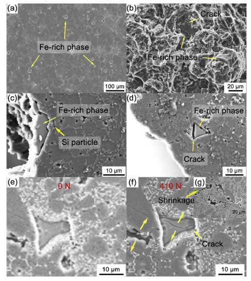
Fig. 8.
The polyhedral Fe-rich (a) and the fracture morphology, (b)-(d) related to polyhedral Fe-rich phases. Polyhedral Fe-rich phase under (e) 0 N and (f) 410 N. Shrinkage under (g) 410 N.
Polyhedral Fe-rich phases fractured in advance before the casting failed. Large crack existing in the interior of the Fe-rich phases served as stress source and provided shortcut for crack propagation. In a finite plate with a center crack, the stress intensity factor KI was dependent on the plate width (W), fracture strength (σ) and crack length (a) [32]:
The geometry factor Y was:
Table 5 lists the geometry factor and the stress intensity factor of shrinkage, planar Si and coarse polyhedral Fe-rich phase. Assuming planar Si and coarse polyhedral Fe-rich phase fractured and the main crack initiated and propagated when the applied force reached the fracture limit, the tensile strength was 230 MPa (537 N) and the average crack length of shrinkage, planar Si and coarse polyhedral Fe-rich phase was 50 μm, 2 μm and 10 μm as shown in Fig. 8(c)-(g), respectively. Because the crack length was much lower than the plate width, i.e. a≪W, the geometry factor Y was ∼1. Table 5 shows that the tip of shrinkage endured the highest elastic stress while the crack in planar Si particle endured the lowest. In this respect, the net shrinkage became the main crack source during the tensile deformation. However, soft ESCs caused KI of shrinkage lower than the theoretical value and restricted further extension of the crack. At this point, densely distributed polyhedral Fe-rich phases (see Fig. 8(a)) became the source of the microcrack and increased stress concentration during tensile deformation.
Table 5 Stress intensity factor of shrinkage, planar Si and polyhedral Fe-rich phase.
| Alloy | Tensile strength (σ) | Average crack length (a) | Geometry factor (Y) | Stress intensity factors (KI) |
|---|---|---|---|---|
| Shrinkage | 230 MPa | 50 μm | 1 | 2.88 MPa⋅m |
| Planar Si particle | 230 MPa | 2 μm | 1 | 0.58 MPa⋅m |
| Polyhedral Fe-rich phase | 230 MPa | 10 μm | 1 | 1.29 MPa·m |
4. Conclusions
In this work, Fe-rich phases in a high-pressure die-cast hypoeutectic Al-Si alloy were characterized using synchrotron X-ray tomography. Particular attention was focused on characterizing the Fe-rich phases and their effects on fracture. Based on the experimental data, the following conclusions can be drawn:
(1)For HPDC AlSi10MnMg alloy, three different morphologies of Fe-rich phases including polyhedral shape, fine compact shape and Chinese script-type shape existed. Polyhedral and fine compact Fe-rich phases belonged to primary phases while Chinese script-type Fe-rich phase was secondary phase participating in a ternary eutectic reaction.
(2)Lower slow-shot speed promoted the polyhedral Fe-rich phase to precipitate in the shot sleeve while decreased the formation of fine compact and Chinese script-type Fe-rich phases in die cavity.
(3)Polyhedral Fe-rich phase with large size had worse deformation compatibility and became stress concentration source, which promoted the generation and propagation of microcracks.
Reference

 WeChat