

1. Introduction
Friction stir lap welding (FSLW) joint is widely applied in aircraft skins, ship decks, railway tankers, etc [1,2] because the joint is welded at solid-phase and has high strength. In the work of Yin et al. [3], they reported that the curved and unbonded lap interface, which is formed because of pin plunge during welding, is called as hook. Hook can induce serious stress concentration and always acts as crack initiation point when a lap joint bears external force. Besides, Song et al. [4] reported that hook reduces the effective sheet thickness of a lap joint since it always bends upwards, and therefore decreased the strength of the lap joint.
Therefore, the researchers have tried various methods trying to reduce or eliminate the hook. Shirazi et al. [5] joined AA5456 aluminum alloy by FSLW and reported that decreasing the rotating speed or increasing the welding speed depresses the vertical material flow during welding, thereby decreasing the hook height. In the work of Yue et al. [6], they reported that a material concentrated zone using the bottom-half-threaded pin locates above the lap interface, which is beneficial to suppress the hook and cold lap. The joint welded by the bottom-half threaded pin has 22.8 % higher failure load than the joint welded by using the conventional full-threaded pin. Wang et al. [7] lap joined 7B04 aluminum alloy using different tools with various pin lengths and found that the hook height first increases and then decreases with increasing the pin length. Furthermore, Yue et al. [8] reported that a tool with a reverse-threaded pin can fabricate joint with smaller hook height and therefore higher joint strength than that fabricated by using a conventional tool. From the above-mentioned references, it is known that no matter how to optimize welding parameters or tool geometry [9,10], hook cannot be eliminated as long as the tool pin plunges into the lower sheet during welding [11,12]. Thus, some researchers have tried pinless tool to reduce or eliminate the hook. Chen et al. [13] lap joined AA6111-T4 and 6082 Al alloys sheets using a pinless tool with a fluted shoulder. The hook cannot be eliminated when the dwell time is shorter than 1 s. Li and his coworkers [14] joined 1.8 mm thick AA2198-T8 Al-Li alloy using a probeless tool with a shoulder having three involute grooves on the shoulder surface and the hook defect cannot be eliminated by changing the dwell time. In another work of their group [15], they found that the hook defect also cannot be eliminated when they use similar tools to join 1.8 mm-thick sheets of AZ31 Mg alloy. Tozaki et al. [16] developed a new tool without probe but with a scroll groove of 0.5 mm depth on shoulder surface for friction stir spot welding 6061-T4 sheets and found that hook still exists at large shoulder plunge depth.
Therefore, in this work, a novel friction stir diffusion bonding (FSDB) method was proposed to eliminate the hook. Three tools with several vortex pins were innovatively designed. The interface bonding characteristic, hook morphology, and mechanical properties of the welded joints were studied.
2. Methods and experiment
2.1. Principle of UASSB
Generally speaking, the stir zone (SZ, donated as yellow color) of a friction stir welding (FSW) joint is wider than the dimension of the pin. There exists a thermal-mechanically affected zone (TMAZ) adjacent to the SZ where the material undergoes both mechanical stirring and frictional heat. If the width of the TMAZ is larger than the distance from the pin tip to the lap interface, a joint can form. However, hook can form if the lap interface undergoes mechanical stirring [17,18]. In this work, FSDB bases on the mechanisms of FSW [19,20] and diffusion bonding [21]. Fig. 1 shows the schematic of FSDB. A tool with several vortex pins (4 pin. for example) on the shoulder is used. The short pin is used during welding, trying to make the TMAZ locate above but not contact the lap interface, and simultaneously make the HAZ cover the lap interface. Thus, the lap interface will undergo large frictional heat but not mechanical stirring during welding. The temperature was tested by using a thermocouple located approximately 1 mm from the shoulder edge (Fig. 1). The tool shoulder exerts a large forging force on the lap interface, providing a powerful condition for diffusion [22]. The bonding between the upper and lower sheets can be formed by diffusion under heat and forging force [23,24]. The pin does not penetrate into the lower sheet, largely depressing the upward material flow, which helps to eliminate hook [25].
Fig. 1.
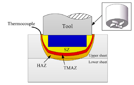
Fig. 1.
Schematic of FSDB.
2.2. Experiment
1.5 mm-thick 2024-T4 Al alloy sheets with alclad layer on its surface were chosen as base material (BM). The BM was cut into 300 mm × 150 mm and then polished by emery papers before welding. Three tools were designed (Fig. 2). Fig. 2(a) shows the tool with two convex-vortex pins and this tool was called as T-tool for convenience. A tool with four convex-vortex pins presented in Fig. 2(b) is called F-tool. Fig. 2(c) gives a tool with six convex-vortex pins (called S-tool). The width and length of the pin were 0.5 mm and 1 mm. The outer radius of the pin is 10 mm. These three tools had the same dimensions except the pin quantity. The diameter of the shoulder is 13.5 mm.
Fig. 2.
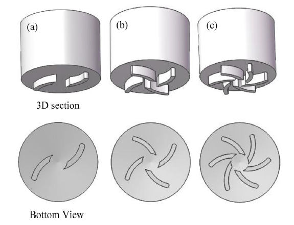
Fig. 2.
Tools used in this work: (a) T-tool, (b) F-tool and (c) S-tool.
The welding was performed on FSW-3LM-4012 machine. Rotating speeds of 500, 600 and 700 rpm, and a constant welding speed of 50 mm/min were used. The shoulder plunge depth was 0.1 mm. The tilting angle of tool axis was 2.5°. The joints were fabricated according configuration B, meaning that the retreating side (RS) of joint bears the main load during lap shear test. After welding, joints were cut perpendicular to the welding direction for metallographic analysis. The specimens were then polished and etched with Keller’s reagent. Joint microstructure was studied using an optical microscope (OM, OLYMPUS-GX71) and a ZEISS scanning electron microscope (SEM). Joint strength was tested on a computer-controlled universal tensile testing machine (INSTRON-8801). A stereoscopic microscope (ZSA403) was used to observe the joint fracture positions. Fracture morphologies were then observed by SEM.
3. Results and discussion
3.1. Cross-sections of the welded joints
Fig. 3 shows the cross-sections of the joints welded by the three tools. The rotating and welding speeds were 600 rpm and 50 mm/min, respectively. The SZs of the three joints all present basin-like morphologies. No macro defect is observed on any joint, indicating that FSDB is suitable for lap welding. Fig. 3(a) shows the joint cross section welded by the T-tool. The original lap interface almost remains intact. Only a small part directly contacts the SZ. Such result shows that the joint is mainly formed by diffusion bonding. During welding, the lap interface is not directly stirred by the tool but undergoes high-temperature (see Fig. 4) caused by the tool rotation. Inter-diffusion of the materials at the upper and lower sheets occurs at high temperature. Moreover, the tool shoulder exerts a large forging force, which can accelerate the diffusion process. Therefore, the upper and lower sheets achieve bonding by the synergistic effects of high temperature and large forging force when using the T-tool. Fig. 3(b) shows the joint cross section welded by the F-tool. The most of the SZ connects the lap interface, meaning that the bonding is achieved by direct material mixing. Only a small part of the lap interface remains intact (Fig. 3(b)), and it is formed by diffusion bonding. Fig. 3(c) shows the cross section of the joint by the S-tool. The entire lap interface is stirred, and the alclad layer curves and extends into the SZ after welding.
Fig. 3.
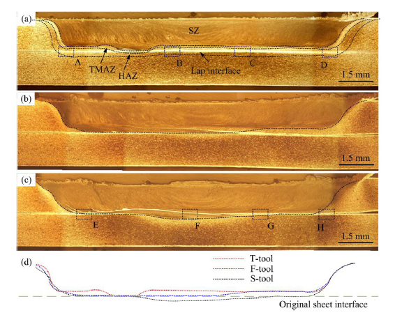
Fig. 3.
Cross-sections of FSLW joints using different tools: (a) T-tool, (b) F-tool, (c) S-tool, and (d) borders of the SZs.
Fig. 4.

Fig. 4.
Temperatures of the testing points using the three tools.
Fig. 3(d) shows the SZ edges of the joints. The SZ edges show rather different morphologies when different tools are used. The most of the SZ locates above the lap interface when using the T-tool, proving that the joint forms basing on diffusion under this condition. On the other hand, the entire SZ locates below the lap interface, indicating that the lap interface is stirred and the joint is formed by material mixing. In fact, the main reason underlying this is the material flow behavior along thickness induced by the increased pin, which will be discussed in the following section.
The thickness of the SZ was measured, trying to show a more clear description of the material flow behavior along thickness. Fig. 5 shows the widths of the SZs along thickness using different tools. The joint welded using the T-tool has a 1.25 mm wide SZ along thickness. Such value is smaller than the thickness of the upper sheet. But sound joint can still form under this condition, proving that the joint is formed by diffusion bonding. The joint welded by the F-tool has a thickness of 1.41 mm, indicating that the material flow behavior along thickness is largely enhanced when using the F-tool. However, such value is still smaller than that of the upper sheet. Therefore, it is seen in Fig. 3(b) that the original lap interface is slightly stirred. It is speculated that the joint is formed mostly by stirring, and partially by diffusion bonding. The joint welded using the S-tool has a 1.55 mm wide SZ along thickness, showing that the material flow behavior is significantly enhanced. As is seen in Fig. 3(c), the original lap interface is stirred when using the S-tool.
Fig. 5.
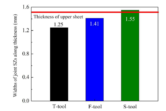
Fig. 5.
Widths of joint SZs along thickness welded using different tools.
Fig. 6 shows the BSE microstructures of the lap interface welded by different tools. Fig. 6(a) shows the images of the lap interface at the advancing side (AS) using the T-tool. The unbounded lap interface shows a flat morphology. Such result shows that the FSDB method in this work can successfully eliminate the hook. Fig. 6(b) and 6(c) shows the microstructures of original lap interface at the joint center. The two sheets are tightly bonded. An alclad layer without crack is observed. Fig. 6(d) shows the lap interface at the RS. Similarly, the un-bonded lap interface shows a flat morphology, indicating that the hook is eliminated at the RS. Fig. 6e shows the lap interface at the AS using the S-tool. The lap interface shows a slightly curved morphology because of the large extrusion force exerted by the tool. Fig. 6(f) and 6(g) shows the microstructures of the original lap interface at the joint center. No crack is observed, either. Similarly, no hook is observed at the RS of the joint (see Fig. 6(h)). The results in Fig. 6 show that the FSDB proposed in this work can eliminate the hook of lap joints. Detailed reason of this will be discussed in the following section. Compared with the work of Chen et al. [13], the FSDB method proposed in this work can join thicker sheets, and good joint surface without serious surface indentation can be obtained. Li et al. [26] and his group eliminated the hook of 1.5 mm thick AA2024-T3 FSSW joint by pinless tools. However, in their work, a subsequent tool stirring processing is needed and the BM is reheated during this process. Yazdi et al. [27] eliminated the hook by using pinless tools with a scroll groove or with l-shaped grooves on the shoulder. However, in their work, a large should plunge depth is adopted and the effective sheet thickness at the SZ is significantly reduced.
Fig. 6.

Fig. 6.
Magnified views of the joint at: (a) A, (b) B, (c) C, and (d) D in
3.2. Material flow behavior
In this section, the material flow behavior using the three tools was simulated by ANSYS FLUENT software. Detailed modeling process has been reported in our previous work [28]. Fig. 7 shows the material flow velocity field using the three tools. The color of the arrow represents the flow velocity and the direction of the arrow represents the flow direction of material. Fig. 7(a) represents the material flow velocity field by the T-tool. The maximum flow velocity of 0.025 m/s is obtained near the pin tip, and the arrows are red. The results in Fig. 7(b) and 7(c) show that the pin geometry has a great effect on the material flow velocity. Fig. 7(b) shows that the maximum flow velocity reaches 0.036 m/s and such value is also obtained near the pin tip. The maximum material flow velocity of 0.041 m/s is obtained when using the S-tool, as shown in Fig. 7(c). The results of Fig. 7 show that higher material flow velocity is obtained when increasing the pin number.
Fig. 7.
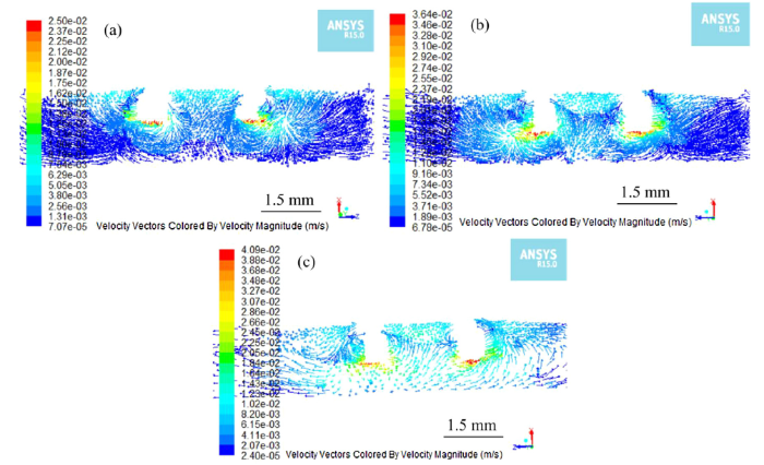
Fig. 7.
Material flow behavior perpendicular to the welding direction by the: (a) T-tool, (b) F-tool, and (c) S-tool.
The material flow behaviors at different sections parallel to the lap interface are analyzed in order to accurately describe the difference when using different tools (see Fig. 8). The distances from section A and section B to the joint upper surface are 0.3 and 1.2 mm, respectively.
Fig. 8.

Fig. 8.
Positions of different sections.
Fig. 9 shows the material flow velocity fields at different sections using different tools. Fig. 9(a) shows the material flow behavior at section A using the T-tool. The maximum velocity value is 0.073 m/s and is obtained at the outer wall of the pin. The material flow velocity increases when using the F-tool and the S-tool (see Fig. 9(b) and 9(c)). The maximum velocity reaches 0.104 m/s and 0.119 m/s when using the F-tool and the S-tool, respectively. The results in Fig. 9(a)-(c) show that higher flow velocities could be obtained when using the tool with more pins. Fig. 9(d) shows the material flow behavior at section B using the T-tool. The maximum velocity reaches 0.018 m/s. Such material flow could generate enough frictional heat input at the lap interface, which is beneficial for the diffusion bonding between the upper and lower sheets. Similarly, higher flow velocities are obtained when using the F-tool and the S-tool. As shown in Fig. 9(e) and 9(f), the maximum velocities reach 0.084 m/s and 0.109 m/s when using the F-tool and the S-tool, respectively. Such high material flow velocity in Fig. 9(f) could directly cause the lap interface to be stirred by the tool, resulting into curved lap interface.
Fig. 9.

Fig. 9.
Material flow velocity fields of section A using the (a) T-tool, (b) F-tool, and (c) S-tool, and of section B using the (d) T-tool, (e) F-tool, and (f) S-tool.
It is seen from Fig. 9 that the material flow velocities at section B are still relatively large when using the three tools in this work. Such phenomena can result into large bonding width at the lap interface of the joint (see Fig. 3). The large bonding width of the lap joints in this work is larger (see Fig. 3) than those obtained using the pinless tools because the material flow velocity decreases significantly along thickness [14,15].
A material flow behavior model during FSDB of this work is shown in Fig. 10. The shoulder and pins drive the material to flow during welding. The material first concentrates below the shoulder then flows downwards. The material released from the pin flows towards the lap interface under the forging force of the shoulder [29]. The downward material flow can exert a large pressure on the lap interface, and this large pressure provides potential powerful condition for the diffusion between the upper and lower sheets. As shown in Fig. 9, there a specific region has relative large material flow velocity but not directly stirred by the pin (the TMAZ). The size of this region becomes larger with increasing the pin number. During welding, the lap interface locates within this region when the S-tool is used (see Fig. 10(b)). The thin and brittle oxide layer on the BM is easily broken under this condition. Afterwards, the bonding between fresh BMs of the upper and lower sheets occurs under the large pressure. However, the pin does no plunge into the lower sheet, so the lap interface does not curve seriously. In the end, no hook forms after welding (see Fig. 6). The material flow becomes relative weak when using the F-tool, resulting into a narrow TMAZ. However, it is believed this region still covers with the lap interface, causing the oxide layer easily to be broken. As shown in Fig. 3(b), a portion of the lap interface is slightly stirred. The material flow becomes further weaker when using the T-tool, resulting into narrower TMAZ compared with those conditions using other tools. The oxide layer on the BM is broken due to the plasticity mismatch between the oxide films and substrates under large pressure. After this, the diffusion effect is still strong enough to form bonding between the upper and lower sheet.
Fig. 10.
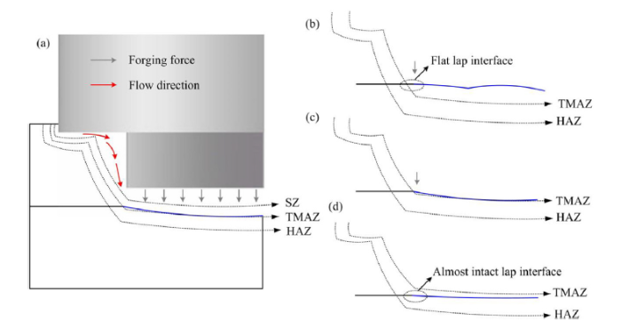
Fig. 10.
Material flow model (a), the lap interface morphology using the S-tool (b), F-tool (c), and T-tool (d).
3.3. Lap shear failure loads and fracture modes
Fig. 11 shows the lap shear failure loads of the joints welded by different tools and rotating speeds. The joints fabricated by the T-tool have failure loads higher than 17 kN. Such high strength indicates that the FSDB method in this work is suitable to fabricate lap joints. The lap shear failure load increases by increasing the rotating speed. As mentioned above, the joining at the interface is formed due to diffusion bonding when the T-tool is used. Consequently, various parameters, such as large plunge depth, high rotating speed, and low welding speed all influence the bonding effect since they can affect the heat input during welding. An increase in rotating speed from 500 to 700 rpm results into an increase in heat input, which is beneficial for diffusion bonding. As a result, the increase of failure load when increasing the rotating speed can be attributed to better bonding at the lap interface caused by increased heat input. For the F-tool, the failure loads of the joints welded at different rotating speeds are rather stable but show no specific variation law. By contrast, the failure loads of the joints welded by using the S-tool are relatively unstable. The maximum lap shear failure load of 19.5 kN is attained when using the rotating speed of 500 rpm. The minimum lap shear failure load of 15.9 kN is attained by using 700 rpm. This can be the softness of the TMAZ caused by increased heat input.
Fig. 11.
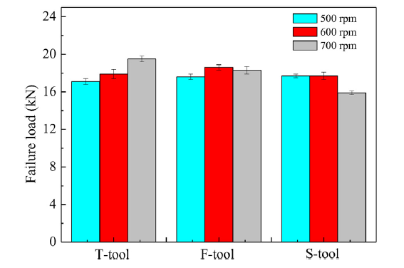
Fig. 11.
Lap shear failure loads of the joints welded by different tools.
Fig. 12 shows the fracture locations of the joints welded by different tools. Fig. 12(a) shows the fracture position of the joint welded using the T-tool. The joint presents a shear fracture and the crack mainly propagates along the original lap interface. This can be attributed to that the relative weak bonding between the upper and lower sheets. We can see in Fig. 3(a) that the most of the lap interface remains intact because of the weak material flow behavior when using the T-tool. The diffusion effect only results into medium-strength bonding at the lap interface. If the joint bears external forces, crack easily initiates from the tip of the lap interface and then propagates along the lap interface, resulting in shear fracture. When using the F-tool and the S-tool, the material flow behaviors at the lap interface are significantly improved, resulting into better bonding at the lap interface. At the same time, higher material flow velocity results into higher heat input [30,31]. The secondary phase particles, which play a strengthening effect [[32], [33], [34]], are dissolved at the TMAZ. Thus, the strength of the TMAZ decreases and joint fractures through the TMAZ, showing a tensile fracture mode. As shown in Fig. 12(b) and 12(c), the crack initiates from the tip of the lap interface and propagates along the TMAZ to the top surface of upper sheet.
Fig. 12.
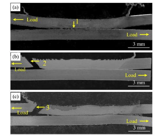
Fig. 12.
Fracture locations of lap joints welded at 600 rpm using: (a) T-tool, (b) F-tool, (c) S-tool.
3.4. Fracture morphologies
Fig. 13 shows the fracture morphologies of the joints welded by different tools. Fig. 13(a) shows the fracture morphologies of region 1 marked in Fig. 12(a). Region 1 locates at the lap interface mainly formed by diffusion bonding. Some dimples are observed, indicating a ductile fracture mode. Such morphology shows that the joint welded by FSDB has excellent bonding at the lap interface. The dimples have specific directivity, and this is formed by the relative movements of the sheets during shear test. Numerous dimples with different sizes are observed at regions 2 and 3 (Fig. 13(b) and 13(c)), and such morphologies also show ductile fracture mode.
Fig. 13.
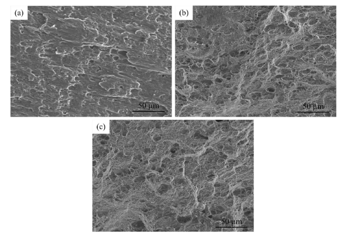
Fig. 13.
Fracture morphologies of lap joints by using: (a) T-Tool, (b) F-tool and (c) S-tool.
4. Conclusions
1 The FSDB process can fabricate lap joint without hook. The joint is formed by the high temperature and the big forging force at the lap interface. The joint welded by the T-tool mainly forms basing on diffusion bonding. The SZ of the joint welded by the F-tool mostly connects with the lap interface, leaving a small part of the lap interface remains intact. The entire lap interface is directly stirred by the S-tool, and the alclad layer curves and extends into the SZ.
2 The material flow velocity is largely increased when increasing the pin number on the shoulder. At section A, the maximum velocity is 0.073 m/s when using the T-tool, which increases to 0.104 m/s and 0.119 m/s when using the F-tool and the S-tool. At section B, the maximum velocity reaches 0.018 m/s when using the T-tool, which increases to 0.084 m/s and 0.109 m/s when using the F-tool and the S-tool.
3 The joints fabricated by the FSDB process have failure load higher than 17 kN. The joint shows shear fracture mode when using the T-tool because the relatively weak bonding at the lap interface. Tensile fracture modes are obtained when using the F-tool and the S-tool because of the softness of the TMAZ.
Acknowledgements
This work is supported by the National Natural Science Foundation of China (No. 51874201).
Reference

 WeChat