

1. Introduction
The advent of 3D printing has ushered in intense research activities on additive manufacturing [[1], [2], [3], [4]]. These fabrication techniques are especially suited for low production runs of highly complex geometrical structures and eliminate the need for joining processes such as brazing and welding. In recent years, there has been increasing interest in incorporating multiple materials into a single build process so as to realize unique properties such as negative thermal expansion coefficients [5,6] and functionally graded materials (FGM). These are composites with constituent concentrations that are spatially varied in a continuous or step-wise gradient. Such graded interface between two dissimilar materials provides a smooth transition of properties at the joint, reducing residual stresses and the risk of delamination between the layers. In recent years, 3D printing has been used to fabricate FGMs with graded dielectric permittivity [7], graded index lenses [8,9], graded modulus in biomimetic soft robot [10], electromagnetic field devices [11], plasmonic materials [12] and in biological implants [[13], [14], [15], [16], [17]].
To date, several strategies to achieve multi-material 3D printing techniques have been employed. For instance, dual print nozzles are commonly used in fused deposition modelling techniques to blend stiff and compliant polymers together in varying ratios to produce polymers with a wide range of modulus [[18], [19], [20], [21], [22]]. Recently, in a study reported by Vijayavenkataraman et al., electrohydrodynamic jetting, a 3D printing process that utilizes high voltage between the nozzle and substrate to extrude very thin fibres in a layer-by-layer manner, was used to fabricate functionally graded scaffolds with pore size gradient [23]. In another study, Zhao et al. used the electron beam melting (EBM) method to synthesize Ti-6Al-4 V mesh structures with spatially varying relative densities, achieving high strength and enhanced energy absorption characteristics [24]. Several other 3D printing techniques, such as selective laser sintering (SLS) [25,26], laser-engineered net shaping (LENS) [27,28] and selective laser melting (SLM) [[29], [30], [31]], have similarly been used to prepare functionally graded structures of titanium alloy, aluminium alloy, steel, zirconia and polylactide.
However, most of the current techniques used for FGM fabrication face a number of limitations. For instance, dual nozzle extruders are typically suitable for thermoplastics only and techniques employing lasers could not be used effectively on materials with high reflectivity, such as Cu and Al based alloys [32]. Oxidation of the metal powders under the intense heat from laser and electron beam techniques is also detrimental, as it often reduces wettability, disrupting interlayer binding and creating regions of weakness within a part [[32], [33], [34]]. Furthermore, the rapid cooling involved in SLS, SLM and EBM can lead to significant build-up of residual stresses, which are responsible for the distortion and even delamination of the final parts [[35], [36], [37], [38]].
In view of these limitations, we propose an alternative technique, namely selective heat melting (SHM), for fabricating multi-material composite structures and FGMs. Selective heat sintering/melting is a 3D printing technique that was previously developed in parallel with SLS and SLM techniques [39], but had largely fallen out of favour since its cost for producing 3D polymeric structures could not compete with Fused Deposition Modelling (FDM) and Stereolithography (SLA) techniques. However, by pairing SHM with a post-processing sintering step, its high throughput, wide material compatibility, small equipment footprint and low cost can be advantageous for 3D printing of composites and FGM. In the present study, we demonstrate these benefits with copper (Cu) - polyethylene (PE) composites fabricated using a custom SHM 3D printer. The present study is concerned with the manufacturing aspects of the SHM technique and therefore, the effects of different processing and material parameters on the physical and mechanical properties of the 3D printed composites will be investigated in detail, while material behaviour during the process are left to future studies.
2. Materials & Methods
2.1. Preparation of powder mixture
Polyethylene colloids with an average diameter of 50 ± 40 μm and melting point of 120 °C (Cospheric LLC, USA), copper particles with diameter ≤ 50 μm and melting point of ∼ 1100 °C (Nanografi Co. Ltd., EU) and iron particles, with diameter ≤ 60 μm and melting point of ∼ 1540 °C (Goodfellow Cambridge Limited, UK) were used as the starting materials to prepare the composites. The melting points were experimentally determined to approximately 10% precision using furnaces, Nabertherm GmbH (HT4/18 and LT5/13). The concentration of copper in the powder mixture was varied from 10 to 30 vol.%. To disperse the particles uniformly, the powder mixtures were mixed in a 15 ml rotating test tube at 14 rpm for 2 h.
2.2. Selective heat melting (SHM) of composite materials
A basic custom-built SHM 3D printing system was used for the present study. The cost of the system was ∼ $400 USD and consisted of a 3-axis linear positioner platform with a repeatable positioning resolution of 1 mm. To control the movement of the positioners, Universal GCode Sender (UGS) was used as the software. A premade HEX file was uploaded to Arduino Uno via a bootloader, XLoader, which allowed the stepper motor of each axis to be controlled discretely, in order to regulate the displacement and velocity of the positioners.
A container for the powder bed, measuring 20 mm × 17 mm, was fixed onto an acrylic platform attached to the translating positioners (Supplementary Information). A stationary metal scraper with a width of 16 mm and a desoldering gun with nozzle diameter of 3.3 mm (TENMA, 21-10130, Rework Station) were positioned above the powder bed container. The temperature and rate of airflow emitted from the desoldering gun can be independently controlled. After a small amount of powder was dispensed into the container, the linear positioner moved the powder bed -1 mm in the Z-axis. This was followed by +25 mm in the X-axis, which allowed the stationary scraper to even out a layer of powder 1 mm thick. This fresh powder bed was then exposed to the hot air from the adjacent desoldering gun. Another movement of -25 mm in the X-axis provided the powder bed with a second exposure of hot air and brought the scraper back to its original position. By repeating these translation operations, structures with length ∼ 20 mm long and layer thickness of 1 mm, were fabricated. Fig. 1 shows the schematic representation of the SHM process used in the present study.
Fig. 1.

Fig. 1.
Schematic representation of custom-built SHM 3D printer.
The effects of processing parameters, such as feed rate (i.e. speed at which the powder bed moved in the X-axis), airflow rate and airflow temperature, on the physical and mechanical properties of 3D printed structures were investigated in detail using composites consisting of 15 vol.% Cu. A fixed set of optimized processing parameters was then used to investigate the effect of composition on the properties of Cu-PE composites.
2.3. Fabrication of CuO foams
The Cu-PE composites obtained in the preceding section can be transformed into CuO foams through sintering in air [Nabertherm GmbH (HT4/18 and LT5/13)] at 950 °C for 60 min with a ramp rate of 5 °C/min [40]. During this high temperature sintering process, the PE colloids undergo thermal decomposition while the Cu particles fused with each other and became oxidized, forming CuO foams. By fabricating a functionally graded Cu-PE composite consisting of 10 vol.%, 15 vol.%, 20 vol.% and 30 vol.% Cu layers of equal thickness (2 mm), a CuO foam with graded porosity can be obtained after the sintering process (Fig. 2).
Fig. 2.

Fig. 2.
Schematic representation illustrating the fabrication of copper oxide foams from a CU-PE composite with graded composition.
2.4. Characterization
Scanning electron microscopy (SEM) was performed using JSM-7600 F (JEOL Inc., Japan) with an accelerating voltage of 2-5 kV. Surface roughness was measured using VK-X1000 (Keyence, Japan) laser scanning confocal microscopy. To gather data for the roughness parameters, five areas were randomly chosen on the surface of each sample. Surface temperature of the powder bed during processing was measured using an infrared thermometer (RS PRO-1327 K, Taiwan). Quasistatic mechanical tests of the samples were carried out using Shimadzu Autograph AG-500A (Shimadzu Corporation, Kyoto, Japan) with a 10 kN load cell at a strain rate of ∼ 0.1 s-1. The sample dimensions were 20 mm × 13 mm × 5 mm and shrinkage of ∼ 10% was observed in all directions after sintering. Mechanical testing was carried out along the direction parallel to the 5 mm dimension. Unless otherwise stated, the mechanical properties reported were averaged over three samples.
3. Results
3.1. Effects of processing parameters
Fig. 3 shows the effect of various SHM processing parameters on the properties of the fabricated composites, consisting of 15 vol.% Cu and 85 vol.% PE, in the form of colour coded tables. Green indicates that the values are desirable while red indicates the opposite. With increased temperature and rate of airflow, the colour coding in Fig. 3 indicates that the surface roughness and failure strength improved, while the resolution generally deteriorated. Similar trends can also be observed, albeit not as robustly, when the feed rate was decreased (Supplementary information). The throughput, on the other hand, improved with higher airflow and temperature as well, but decreased with lower feed rate, which is expected. In the present study, throughput refers to the volume of powder that can be fused per unit time (= feed rate × layer thickness × width of single pass) and is inversely related to the resolution of the technique, which is expressed as the ratio of the minimum printable voxel diameter to the nozzle diameter.
Fig. 3.
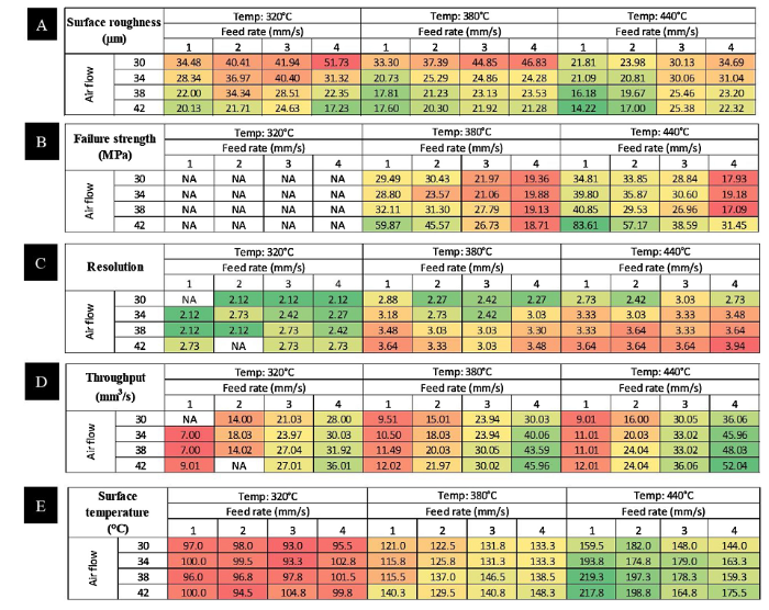
Fig. 3.
Effect of SHM processing parameters on (A) surface roughness, RA (μm), (B) failure strength (MPa), (C) resolution, expressed as a ratio of the minimum printable diameter to the nozzle diameter, (D) throughput (mm3/s) and (E) surface temperature (°C), averaged over four passes. In all cases, the composition of the material was 15 vol.% Cu and 85 vol.% PE. The tables were colour coded on a green- red scale, where green was used to highlight the desirable values.
The main reason that smoother and stronger Cu-PE composites can be synthesized with lower precision at low feed rates, high airflow rate and high temperature of airflow is because these processing conditions encourage greater heat transfer by lengthening the transfer time (low feed rate) or increasing the amount of thermal energy incident upon the powder bed (high airflow rate and temperature). A better heat transfer would enable the PE particles to melt and bind the Cu particles more effectively, leading to a less porous structure with smoother surface and greater strength [40]. This also caused the excess heat to diffuse to greater distances laterally, reducing the resolution, but increasing the throughput for a given feed rate.
To determine this, the surface temperature of the powder bed during processing was recorded in Fig. 3(e). It can be observed that it followed the same trend as that for surface roughness, failure strength and resolution i.e. samples with low surface roughness, high strength and low resolution had been subjected to higher surface temperatures, indicating that more heat was transferred to the powder bed. For instance, at an airflow temperature of 440 °C, feed rate of 1 mm/s and flowrate of 42 mm3/s, the sample had the lowest surface roughness (14.22 μm), highest failure strength (83.6 MPa) and second worst resolution (3.64) at one of the highest surface temperature recorded (218 °C).
A detailed examination of Fig. 3(e) also reveals that the surface temperature of the powder bed did not exceed the sintering (110 °C) or melting temperature (120 °C) for the PE colloids at an airflow temperature of 320 °C, suggesting that the PE particles did not fuse with each other or with the Cu particles [41]. For this reason, no mechanical data could be extracted for samples subjected to an airflow temperature of 320 °C, as they crumbled upon removal from the powder bed. In contrast, the PE colloids had melted and spread evenly across the Cu particles when the airflow temperature was above 320 °C (Fig. 4, Fig. 5). Moreover, it appears that at low feed rate (1 mm/s), the microstructures of the Cu-PE composites were less porous than that fabricated at high feed rate (4 mm/s) (Fig. 4). Similarly, composites fabricated at 440 °C showed visibly lesser pores in comparison to composites fabricated at 380 °C (Fig. 4).
Fig. 4.

Fig. 4.
FE-SEM images of composites consisting of 15 vol.% Cu and 85 vol.% PE fabricated using SHM technique at varying feed rate, air flow rate and temperature of air flow.
Fig. 5.

Fig. 5.
(A) SEM image of composites consisting of 15 vol.% Cu; EDS mapping showing (B) Cu and PE (C) Cu only and (D) PE only.
Temperatures above 440 °C were not utilized in the present study as it was observed that excessive heat transfer led to aggressive melting of the PE and the balling effect, where the surface tension of the melted powder dominated and forced the melted matter into a spherical shape in order to reduce surface energy [32,33,42]. This balling effect led to poor deposition of new layers, causing porosity and delamination. Hence, an optimum processing temperature, airflow and feed rate are important for the fabricated structures to exhibit a dense microstructure with low porosity. For this reason, the processing conditions of airflow temperature =440 °C, feed rate = 1 mm/s and flow rate = 42 mm3/s were selected to investigate the effect of composition on the properties of the Cu-PE composites in the following.
3.2. Effect of composition on the mechanical properties of Cu-PE composite
Fig. 6 shows the effect of PE content on the peak stress and energy absorbed per unit volume by the Cu-PE composites. From Fig. 6(a) and (b), it can be seen that the highest failure stress (60 ± 3.3 MPa) and energy absorption at strain = 0.6 (7.3 ± 0.79 MPa) were obtained at a PE content of 80 vol.%. These findings suggest that at low PE content, there were insufficient PE colloids to serve as a binder to create a strong bond between PE colloids and Cu particles. At excessively high PE concentrations, however, the composite weakened considerably due to the lack of Cu particles.
Fig. 6.

Fig. 6.
Effect of PE content on (A) the failure stress and (B) energy absorbed at 60% strain for Cu-PE composites; (C) Ashby chart with orange crosses representing the average strength-density properties of the Cu-PE samples reported in (A).
Fig. 6(c) shows an Ashby plot that compares the specific strength of the Cu-PE composites with other materials. It can be observed that the Cu-PE composites exhibited similar performance to engineering plastics such as polycarbonate, which is widely used for impact protection in sports and electronic equipment (e.g. mobile phone cases, knee and elbow pads, snowboards etc.) [[43], [44], [45]], despite PE being one of the weakest thermoplastic available [46,47]. Furthermore, the Cu-PE composites fabricated in this investigation has an added advantage of being electrically conductive, with an average conductivity value of 0.152 ± 0.28 S/m, which is comparable to the physically cross-linked graphene assemblies [48,49]. As such, the Cu-PE composites fabricated can be used as an alternative material to polycarbonate in applications where electrical conductivity is important, such as for electromagnetic shielding [[50], [51], [52], [53]]. In addition, because these Cu-PE composites are compatible with 3D printing, the material can be combined with judicious structural design to further maximize its functionalities.
3.3. Mechanical properties of CuO foams
By subjecting the Cu-PE composites to a high-temperature debinding and sintering step at 950 °C, CuO foams can be formed [54,55]. Fig. 7 shows the SEM images of CuO foams with relative densities (i.e. solid fraction) of 0.32, 0.37, 0.42 and 0.45 (i.e. porosities of 68%, 63%, 58% and 55%), which were fabricated from Cu-PE composites with Cu volume fractions of 0.10, 0.15, 0.20 and 0.30 respectively. The structures appear to be three dimensionally interconnected and it can be qualitatively observed that the porosity was inversely related to the copper volume fraction. Since diffusion occurred within the confined geometry set by the PE colloids, the short range diffusion of the metal nuclei seems to have led to a more connective structure. Similar findings have been reported by Kim et al. on CuO foams fabricated using electrospun non-woven polymer fabric as a sacrificial template [56].
Fig. 7.

Fig. 7.
Scanning electron microscopy images of CuO foams with Cu fraction of (A) 10 vol.%, (B) 15 vol.%, (C) 20 vol.% and (D) 30 vol.%.
Fig. 8 shows the effect of relative density on peak stress, σy*, and energy absorption characteristics of the CuO foams. The energy absorption per unit volume, W, of the CuO foams was determined quantitatively from the area under the stress-strain curve up to the densification strain (∼ 60%). From Fig. 8(a) and (b), it can be seen that the peak stress and energy absorption values of the CuO foams increased with an increase in the relative density, ρ/ρs, where ρ refers to the density of the porous material and ρs refers to the density of a fully solid material.
Fig. 8.

Fig. 8.
Effect of relative density on peak stress and energy absorbed per unit volume of CuO foams. The data points are the experimental values while the dotted lines represent the best fit lines with a power law relation.
According to the classic strength and energy absorption scaling laws derived by Gibson and Ashby [57] for porous foams:
and
where σys refers to the constituent material’s yield or failure strength.
However, the experimentally obtained exponent values for the relative strength, σy*/σys, and W for the CuO foams were 2.9 and 1.8 respectively (Fig. 8), which were much higher than Gibson-Ashby’s prediction. This deviation, which was observed in previous studies as well [58], is mainly due to the large solid fractions of CuO foams in the present study, as the Gibson-Ashby relations generally only hold for porous structures with relative densities less than 30% [47]. This is supported by the observation that the peak stresses (3.9-11.5 MPa) exhibited by the CuO foams here (Fig. 8(a)) are in line with those previously reported for ceramic foams of similar relative densities [59]. Furthermore, the trend in Fig. 8(a) predicts that the peak stress for a fully dense CuO would be 107.74 MPa, which agrees very well with the previously reported value of 110 MPa [60]. These results suggest that the Cu particles were sintered and fully oxidized to CuO foams, and any presence of residual Cu was insignificant.
3.4. Mechanical response of functionally graded CuO foams
Fig. 9 shows the typical stress-strain behaviour of a functionally graded CuO foam. The first and second peak stresses occurred at ∼ 0.1 MPa, which correspond to the peak stress of CuO foams with relative densities 0.32 and 0.37, formed from composites consisting of 10 and 15 vol.% Cu. The third and fourth peaks occurred at 0.23 MPa and 0.3 MPa, which correspond to the peak stresses of CuO foams with relative densities 0.42 and 0.45, obtained from sintered composites consisting of 20 and 30 vol.% Cu respectively. The presence of these individual peaks indicated that the functionally graded foam was failing layer by layer, starting with the weakest one with a relative density of 0.32 and ending with the strongest layer with a relative density of 0.45. After all the layers have failed and densified, the stress rose steeply. Similar observations have also been reported for an Al/Cu hybrid foam [61] and other functionally graded metal foams [62].
Fig. 9.

Fig. 9.
(A) Schematic illustration of the composition gradient in the Cu-PE composite, (B) functionally graded CuO foams after sintering and (C) stress-strain behavior of functionally graded CuO foams (insets: stress-strain behaviors of foams with relative densities of 0.32 (black), 0.37 (purple), 0.42 (green) and 0.45 (red)).
4. Discussion
Based on the results presented, it is clear that selective heat melting (SHM) can be successfully employed to 3D print metal-polymer composites, as well as ceramic foams, with the help of a post-printing high temperature treatment. By spatially varying the constituent concentrations of the composites, functionally graded materials can also be produced. These materials were shown to be mechanically strong and tough, with the Cu-PE composites demonstrating serviceable electrical conductivity as well.
The two main factors influencing the mechanical and physical properties of the Cu-PE composites were the ratio of metal to binder particles and the amount of heat transferred during the 3D printing process. If the volume concentration of Cu is high, the lack of polymeric binder causes the resultant composite to be soft and weak, but an excessively low concentration of Cu would reduce its reinforcement effect on PE, leading to the same result. The optimal Cu concentration is therefore, somewhere in the middle. For the processing parameters used here, the value was determined to be approximately 20 vol.%. Our results also show that a greater amount of heat transferred to the PE particles would enable them to melt more thoroughly and bind the Cu particles more strongly. This can be accomplished by having a slower feed rate (more time for heat transfer) and higher airflow temperature and faster airflow rate, both of which contribute to a higher rate of heat transfer. Excessive heating, however, may cause too much of the PE to melt at once, resulting in balling i.e. parts of the Cu-PE powder mixture is reduced to a spherical shape due to surface tension effects.
Compared to SLA and FDM techniques, the main advantage of SHM is that no support structures are needed to produce overhanging features. Good dispersion of the fillers is more easily achieved, since the mixing is done in solid powder form rather than in liquid resins. A wider range of polymers are compatible with the process, as they do not have to be UV sensitive or have low viscosity, which are prerequisites for SLA and FDM techniques respectively [63,64].
Compared to conventional powder bed processes such as SLS, SLM and EBM, SHM equipment is significantly cheaper and can be made smaller (desktop size). The process itself does not involve rapid heating and cooling, which can lead to significant metal oxidation, excessive shrinkage and build-up of residual stresses [32]. Furthermore, SHM has wider material compatibility where almost all metal and ceramic filler powders are suitable. In contrast, it can be difficult for laser techniques to 3D print certain materials, such as Al and Cu, due to the highly reflective nature of its particles [32,65]. As a simple proof of this, composites consisting of alternating layers of Cu-PE and Fe-PE were fabricated via the SHM technique (Fig. 10).
Fig. 10.

Fig. 10.
(A) Side view and (B) isometric view of the alternating layers of Cu-PE (15 vol.% Cu and 85 vol.% PE; brown) and Fe-PE (15 vol.% Fe and 85 vol.% PE; grey) fabricated using the SHM technique.
The main drawbacks of SHM are low print resolutions, which can be mitigated with finer nozzles, and the greater porosity inherited from the presence of polymeric binder particles. In addition, a separate furnace is required for post-processing if the binder particles are to be removed, which may not be necessary with other 3D printing techniques. Nevertheless, our results suggest that SHM can be a good complement to existing 3D printing techniques for producing multi-material composites and functionally graded materials with useful mechanical properties and surface finishing.
5. Conclusion
Selective heat melting was employed in the present study to fabricate Cu-PE composites, CuO foams and functionally graded CuO foams. Our results showed that optimum processing conditions such as high airflow temperature, low feed rate and high airflow rate are essential for the heat transfer process that enabled PE to melt and bind with Cu particles. Based on the optimized processing conditions, Cu-PE composites with varying Cu content were successfully fabricated. These composites had strength similar to polycarbonate and electrical conductivity comparable to 3D graphene assemblies. The strongest composites were found to have a composition of 80 vol.% PE, since excessive PE concentration reduces the strengthening effect of Cu particles, while too little PE led to deficient binding of the Cu particles. CuO foams were fabricated by subjecting these Cu-PE composites to high temperature heat treatment to remove the polymeric binders, as well as to fuse and oxidize the Cu particles. By spatially varying the relative concentrations of Cu and PE of the composites before the high temperature treatment, functionally graded CuO foams were fabricated and it was shown that these foams exhibited a layer-by-layer failure mechanism. The insights derived from this study suggest that selective heat melting can complement existing 3D printing techniques in producing multi-material composites and functionally graded materials.
Acknowledgements
The authors would like to acknowledge partial funding for this project by the Temasek Research Fellowship (No. 9016100729).
Appendix A. Supplementary data
Supplementary material related to this article can be found, inthe online version, at doi: https://doi.org/10.1016/j.jmst.2019.12.016.
Reference
DOI
URL
PMID
[Cited within: 1]

Roboticists have begun to design biologically inspired robots with soft or partially soft bodies, which have the potential to be more robust and adaptable, and safer for human interaction, than traditional rigid robots. However, key challenges in the design and manufacture of soft robots include the complex fabrication processes and the interfacing of soft and rigid components. We used multimaterial three-dimensional (3D) printing to manufacture a combustion-powered robot whose body transitions from a rigid core to a soft exterior. This stiffness gradient, spanning three orders of magnitude in modulus, enables reliable interfacing between rigid driving components (controller, battery, etc.) and the primarily soft body, and also enhances performance. Powered by the combustion of butane and oxygen, this robot is able to perform untethered jumping.
DOI
URL
PMID
[Cited within: 1]
The concept of transformation optics (TO) is applied to control the flow of electromagnetic fields between two sections of different dimensions through a tapering device. The broadband performance of the field taper is numerically and experimentally validated. The taper device presents a graded permittivity profile and is fabricated through three-dimensional (3D) polyjet printing technology using low-cost all-dielectric materials. Calculated and measured near-field mappings are presented in order to validate the proposed taper. A good qualitative agreement is obtained between full-wave simulations and experimental tests. Such all-dielectric taper paves the way to novel types of microwave devices that can be easily fabricated through low-cost additive manufacturing processes.
DOI
URL
PMID
[Cited within: 1]
The cementless fixation of porous coated femoral stems is a common technique employed for Total Hip Arthroplasty (THA). With the rate of revision surgery appearing to rise and younger more active patients requiring primary surgery it can be thought that alternative methods for increasing implant longevity need to be considered. The stress shielding of periprosthetic bone still remains a contributing factor to implant loosening, caused through a mismatch in stiffness between the implant and the bone. However, the ability to achieve stiffness matching characteristics is being realised through the use of Additive Layer Manufacturing (ALM) technologies and Functionally Graded Materials (FGM). This paper proposes an alternative design methodology for a monoblock Cobalt Chrome Molybdenum (CoCrMo) femoral stem. It hypothesises that a femoral stem suitable for cementless fixation can be manufactured using Laser Melting (LM) technology offering orthotropic functionally graded porous structures with similar mechanical properties to human bone. The structure and mechanical properties of the natural femur have been used as a basis for the design criteria which hypothesises that through a combination of numerical analysis and physical testing, an optimal design can be proposed to provide a lightweight, customised femoral stem that can reduce the risk of implant loosening through stress shielding whilst maintaining bone-implant interface stability.
DOI
URL
PMID
[Cited within: 1]
Current hip replacement femoral implants are made of fully solid materials which all have stiffness considerably higher than that of bone. This mechanical mismatch can cause significant bone resorption secondary to stress shielding, which can lead to serious complications such as peri-prosthetic fracture during or after revision surgery. In this work, a high strength fully porous material with tunable mechanical properties is introduced for use in hip replacement design. The implant macro geometry is based off of a short stem taper-wedge implant compatible with minimally invasive hip replacement surgery. The implant micro-architecture is fine-tuned to locally mimic bone tissue properties which results in minimum bone resorption secondary to stress shielding. We present a systematic approach for the design of a 3D printed fully porous hip implant that encompasses the whole activity spectrum of implant development, from concept generation, multiscale mechanics of porous materials, material architecture tailoring, to additive manufacturing, and performance assessment via in vitro experiments in composite femurs. We show that the fully porous implant with an optimized material micro-structure can reduce the amount of bone loss secondary to stress shielding by 75% compared to a fully solid implant. This result also agrees with those of the in vitro quasi-physiological experimental model and the corresponding finite element model for both the optimized fully porous and fully solid implant. These studies demonstrate the merit and the potential of tuning material architecture to achieve a substantial reduction of bone resorption secondary to stress shielding. (c) 2016 Orthopaedic Research Society. Published by Wiley Periodicals, Inc. J Orthop Res 35:1774-1783, 2017.
DOI
URL
PMID
[Cited within: 1]
Self-assembly of two-dimensional graphene sheets is an important strategy for producing macroscopic graphene architectures for practical applications, such as thin films and layered paperlike materials. However, construction of graphene self-assembled macrostructures with three-dimensional networks has never been realized. In this paper, we prepared a self-assembled graphene hydrogel (SGH) via a convenient one-step hydrothermal method. The SGH is electrically conductive, mechanically strong, and thermally stable and exhibits a high specific capacitance. The high-performance SGH with inherent biocompatibility of carbon materials is attractive in the fields of biotechnology and electrochemistry, such as drug-delivery, tissue scaffolds, bionic nanocomposites, and supercapacitors.
AbstractThe compressive properties of porous copper with relative densities, ρ/ρs, of 0.22–0.96 were investigated. In the low relative density range (ρ/ρs < 0.5–0.6), porous copper showed a density exponent n of 2.3, where n represents the relative density dependence of yield strength. In this range, the bending and buckling of cell walls and the formation of macroscopic deformation bands were observed. However, porous copper with a higher relative density (0.5–0.6 < ρ/ρs < 0.9–1) had an n value of ∼1, where the dominant deformation mode of cell walls was yielding, and no clear deformation band was observed. Also, in the highest relative density range (ρ/ρs very close to 1), the compressive properties degraded markedly with decreasing density, indicating that stress concentration around the minimal pores occurred in this density range.]]>

 WeChat