

1. Introduction
In recent years, the dissimilar joining of multi-materials has become one of the most critical and challenging issues in both the academic and industrial fields since it is not only effective to lower the vehicles’ weight, which reduces the energy consumption and CO2 emissions, but also allows to incorporate multi-functions into one joint, hence enabling to provide appropriate functions to specific applications [[1], [2], [3], [4], [5], [6]]. Among the multiple hybrid metal combinations, since the dissimilar joining of titanium alloys and stainless steels enables an incorporation of lightweight, low cost, excellent mechanical properties, great corrosion resistance and good biocompatibility, it has gained more and more interest and demand for use in the cryogenic, nuclear, chemical, and biomedical industries [[7], [8], [9], [10], [11]]. Conventional fusion welding has been adopted to join titanium to steel [[12], [13], [14]]. However, the significant difference in the chemical and physical properties between them can induce severe distortion and residual stress in joints. Moreover, the extremely high welding temperature can cause the formation of the thick and brittle Ti-Fe series intermetallic compound (IMC) layers at the weld interfaces. Both of these significantly deteriorate the mechanical properties of the fusion welded titanium/steel joints [10,15,16]. Friction welding (FW) is a solid-state joining technique in which friction heat is generated on the faying surfaces of two components which softens the interface materials, then the soft interface materials are plasticized and pumped out to the outer region as flash under the axial force to finally produce a joint. Since FW enables a joining at a much lower welding temperature than fusion welding which benefits in avoiding the fusion-welding-associated problems, and with a much shorter welding time than diffusion welding which improves the manufacturing efficiency, it has been proved to be the most effective method for the dissimilar joining of titanium alloys and stainless steels [[17], [18], [19], [20], [21], [22]]. Li et al. [17] performed the FW of Ti-6Al-4V alloy (Ti64) and SUS321 stainless steel and investigated the effect of the friction time on the interface microstructure and mechanical properties of the joints. A strong metallurgical bond was reported to be achieved at the weld interface with the IMC zone less than 3 μm in width, and the optimal friction time to obtain the sound joint was within 3~4 s. The Ti64 and 316L stainless steel were also friction welded by Li et al. [18]. The inhomogeneous weld interface microstructure and corresponding inhomogeneous mechanical properties were confirmed and the effect of the post-weld heat treatment was examined. Kumar et al. [11] friction welded Ti64 and SS304L stainless steel with copper used as the interlayer and without any interlayer. They found that the joints with the copper interlayer showed much higher tensile strength because the copper interlayer played an important role in preventing the formation of the cracks, martensite, and brittle Ti-Fe IMCs. Even though several additional studies [16,19,23,24] have also been conducted on the FW of Ti64 and stainless steels, none of the fabricated joints showed an ideal tensile strength comparable to the base material (BM) strength. More importantly, most of the previous studies mainly concentrated on the variation in the processing parameters, resultant interface or near-interface microstructure and mechanical properties of the obtained joints. However, how the processing parameters affect the two dominating factors: the thermal cycle and materials deformation during the FW, has still not been discussed, although they fundamentally influence the resultant microstructure and mechanical properties. Consequently, the emphasis in the present study is placed upon to propose the principle for obtaining high joint quality via processing parameter optimization in the FW of titanium alloys and stainless steels.Ti64 and SUS316L stainless steel (SUS316L) were friction welded with the processing parameters optimization to obtain a sound dissimilar joint. The interface microstructure and mechanical properties of the obtained joints as well as the interface microstructural evolution during the FW were systematically investigated in order to clarify how the processing parameters work in the dissimilar FW of titanium alloys and stainless steels.
2. Experimental procedure
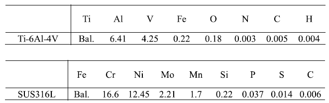
As-received Ti64 and SUS316L rods of 100 mm in length and 10 mm in diameter were used as the BM. The chemical compositions of both materials are listed in Table 1. The faying surfaces of both materials were lathe manufactured, then ultrasonically cleaned using acetone and ethanol.
Table 1 Chemical compositions of Ti-6Al-4V and SUS316L stainless steel used in the present study (mass%).
 |
The specimens were friction welded using a FW machine (NITTO SEIKI FF-20Ⅲ+SP) under the different friction pressures of 180 MPa, 300 MPa, and 500 MPa, at the constant rotation speed of 300 rpm and constant burn-off length of 4 mm in air (the burn-off length is the linear measurement of the materials consumed or plasticized out to the outer region as flash during the FW). The FW was further conducted at 500 MPa, 100 rpm, 4 mm in air and with an external liquid CO2 cooling during the entire processing, which was called “on-line CO2 cooling”. Liquid CO2 were injected towards the friction interface from two opposite directions nearly perpendicular to the specimen axis through two ellipse-shaped injection ports having a long axis of ~5 mm and a short axis of ~2 mm. The distance between the injection port and the specimen surface was ~25 mm. Two holes with a diameter of 1.2 mm and different depths of 5.0 mm and 2.0 mm parallel to the radius direction were machined on the transverse cross section of the SUS316L side ~1.5 mm distant from the faying surface. K-type thermocouples (As One Corporation; KTO-10200M3) were then inserted into the 5.0 mm and 2.0 mm deep holes to measure the thermal cycles that occurred at the weld interface center and periphery, respectively, during the FW with a sampling time of 20 ms.
The longitudinal cross section specimens were prepared from the joints using an electrical discharge machine (EDM; Sodick AG360L). They were mechanically polished using waterproof SiC emery papers of up to 4000 grit and buff polished using a colloidal SiO2 suspension, then subjected to a macroscopic observation using a 3D measuring macroscope (KEYENCE VR-3200) and a microstructural analysis using a scanning electron microscope (SEM; JEOL JSM-7001FA) equipped with an energy disperse X-ray spectrometer (EDS). Thin foil specimens were sliced at the weld interface center and periphery from the longitudinal cross section specimen with the foil surface perpendicular to the cross section surface and the foil normal direction parallel to the weld interface. The sliced foils were then subjected to a microstructural inspection by scanning transmission electron microscopy (STEM; JEOL JEM-2100F) and EDS under the STEM mode at an accelerating voltage of 300 kV.
The dog-bone shaped tensile specimens with a gauge length of ~60 mm and a gauge diameter of ~9.0 mm were prepared from the joints using the lathe machining, then they were subjected to the room-temperature tensile tests using a mechanical testing machine (SHIMADZU Autograph AG-10TB) at a cross-head speed of 1 mm/min. The Vickers hardness was measured on the longitudinal cross section specimen along the blue dotted line which is perpendicular to the weld interface under a load of 0.98 N for a dwell time of 15 s using a hardness tester (FUTURE-TECH FM-800). All the mentioned temperature measurements, specimen preparations for the macro- and micro-structural analyses, tensile tests as well as the hardness tests are schematically illustrated in Fig. 1.
Fig. 1.

Fig. 1.
Schematic illustrations of temperature measurement by thermocouples and specimen preparations for macro- and micro-structural observations, tensile test and hardness test.
3. Results and discussion
3.1. Effect of friction pressure on joints’ microstructure and mechanical properties
Fig. 2(a) shows the macrographs of the longitudinal cross sections of the joints fabricated at the constant 300 rpm, constant 4 mm, and different friction pressures of 180 MPa, 300 MPa, and 500 MPa in air; the weld interfaces are indicated by the red dotted lines. It is noted that the weld interface fabricated at 180 MPa is quite flat, while those fabricated at 300 MPa and 500 MPa show curvature morphologies bulging from the Ti64 side to the SUS316L side. In addition, the Ti64 and SUS316L exhibit different deformation behaviors in the obtained joints. Ti64 shows a deformation mainly concentrated nearby the weld interface, while the SUS316 L has a gradient deformation in which the deflection gradually decreases with the distance from the weld interface. Moreover, as the friction pressure increases, the total deflection gradually decreases for Ti64 but increases for SUS316L. The corresponding SEM micrographs of the weld interfaces center and the EDS line analysis along the red solid lines perpendicular to the weld interfaces are shown in Fig. 2(b). A relatively wide Ti/Fe diffusion zone having a width of ~2.4 μm is identified at the weld interface fabricated at 180 MPa, while the width of the diffusion zone gradually decreased to ~1.0 μm and ~0.5 μm with the friction pressure increased to 300 MPa and 500 MPa, respectively. These results indicate that the welding temperature can be reduced by increasing the applied pressure during the FW of titanium alloy and stainless steel, which well agrees with a previous study that reported similar results for the linear friction welding of medium carbon steel [25,26]. In addition, it is worth noting that both the Cr-rich zone and Ni-rich zone can be identified within the diffusion zone of the joint fabricated at 180 MPa with the Cr-rich zone close to SUS316L and the Ni-rich zone next to Ti64. This is attributed to the fact that these elements have a diffusion-coefficient magnitude order of Ni > Fe > Cr in titanium as reported in the literature [27]. However, no obvious Cr- or Ni-rich zone is visible within the diffusion zones of the joints fabricated at 300 MPa and 500 MPa which is due to the limited mutual elemental diffusion.
Fig. 2.

Fig. 2.
(a) macrographs of longitudinal cross sections of the joints fabricated at 300 rpm, 4 mm, and different friction pressures of 180 MPa, 300 MPa, and 500 MPa; (b) corresponding SEM micrographs of weld interfaces center and EDS line analysis along the red solid lines perpendicular to the weld interfaces.
Since the increasing friction pressure suppressed the mutual elemental diffusion, hence suppressing the formation of the Ti-Fe series IMC layers, it was expected to have a somewhat positive effect on the joints’ mechanical properties. However, all the obtained joints show the similar tensile strength of ~140 MPa which is much lower than that of the SUS316L BM (~650 MPa) based on the tensile data shown in Fig. 3. In order to figure out this unexpected phenomenon, the weld interface microstructure of the fabricated joints was inspected by SEM; the corresponding results are shown in Fig. 4. In the joint fabricated at 180 MPa, a layer with a width of ~12 μm, in which materials having the Ti64 contrast and the SUS316L contrast seem to be well mixed, can be observed at the weld interface center (Fig. 4(a)). Small voids are also visible on the border of the layer as indicated by the red circle in Fig. 4(a). This “well mixed” layer having a much larger width of ~40 μm is observed at the weld interface periphery (Fig. 4(b)). In addition to the small voids, large cracks are also apparently seen on the border of the layer and also along the ~45° shear direction within the layer. For the joint fabricated at 500 MPa, a similar “mixed” layer with lots of voids and cracks formed on the border and within the interior of the layer is also observed at the weld interface periphery (Fig. 4(d)). These “mixed” layers were then subjected to an SEM-EDS analysis and a Vickers hardness measurement; the results are shown in Fig. 5. The SEM-EDS results of the layer formed at the weld interface periphery fabricated at 500 MPa (Figs. 4(a) and 4(b)) suggest that both the Ti64 and SUS316L are mechanically mixed layer by layer and the Ti-Fe series IMCs such as TiFe and TiFe2 seem to be identified within the layer. The Vickers hardness results of the layer derived from the weld interface periphery fabricated at 180 MPa (Fig. 5(c)) show that the mechanically mixed layer has an extremely high hardness of ~1200 Hv compared to those of the Ti64 (~400 Hv) and SUS316L (~350 Hv) BM. Based on these results, it is inferred that the Ti64 and SUS316L were mechanically mixed during the FW which produced a “mechanically mixed layer” at the weld interface. It should be noted that this is the first time to detect and well identify these mechanically mixed layer structures at the weld interface in the FW joint of Ti64 alloy and stainless steels compared to the other related studies [11,[16], [17], [18], [19],23,24] on FW of Ti64 alloy and stainless steels to the best of the authors’ knowledge. Lots of IMC products accordingly formed throughout the entire layer due to the intense mutual element diffusion, making the layer extremely hard and brittle. Peeling and fracture thus occurred on the border or in the interior of the brittle layer due to the intense friction and deformation at the weld interface, which resulted in the voids and cracks formation. These voids and cracks significantly deteriorated the joints’ mechanical properties, which well explains the previously mentioned unexpected phenomenon. Nevertheless, it should be noted that neither the mechanically mixed layers nor voids and cracks are visible at the weld interface center of the joint fabricated at 500 MPa as shown in Fig. 4(c). In combination with the significantly suppressed mutual diffusion and IMC formation as mentioned in Fig. 2, the weld interface center fabricated at 500 MPa is thus considered the most ideal among all in the above fabricated joints.
Fig. 3.

Fig. 3.
Tensile strength of the joints fabricated at 300 rpm, 4 mm, different friction pressures of 180 MPa, 300 MPa, and 500 MPa in air, in comparison with that of the SUS316L BM.
Fig. 4.

Fig. 4.
SEM microstructure of the weld interfaces of the joints fabricated at 300 rpm, 4 mm, and different friction pressures of (a-b) 180 MPa and (c-d) 500 MPa.
Fig. 5.

Fig. 5.
(a-b) SEM-EDS results of the “mixed” layer formed at weld interface periphery fabricated at 300 rpm, 4 mm, and 500 MPa; (c) Vickers hardness results of the layer formed at weld interface periphery fabricated at 300 rpm, 4 mm, and 180 MPa.
3.2. Effect of rotation speed and on-line CO2 cooling on joints’ microstructure and mechanical properties
In order to obtain this “ideal” microstructure throughout the entire weld interface, it is first necessary to clarify the difference in the experienced processing conditions between the weld interface center and periphery in the joint fabricated at 500 MPa and 300 rpm. Compared to the periphery, the weld interface center is known to possess a lower linear velocity and a resulting lower heat generation rate (i.e., temperature increasing rate) according to the following local heat generation equation [28]:
where N is the heat power, p is the unit pressure, f is the friction coefficient, v is the linear velocity and r is the local radius. Based on these findings, the friction pressure and burn-off length were maintained as 500 MPa and 4 mm, respectively, and the rotation speed was reduced from 300 rpm to 100 rpm to narrow the gap in the linear velocity and heat generation rate between the weld interface center and periphery. Furthermore, liquid CO2 was sprayed during the FW conducted at 500 MPa and 100 rpm to further minimize the heat-generation-rate difference between the weld interface center and periphery. These processing modifications are schematically illustrated in Fig. 6.
Fig. 6.

Fig. 6.
Schematic illustrations of processing modifications including rotation speed reduction and on-line CO2 cooling in friction welding.
The macrographs of the longitudinal cross sections of the joints fabricated at these modified processing conditions are shown in Fig. 7(a); that of the joint fabricated at 500 MPa, 300 rpm, 4 mm is also shown for comparison. The weld interface fabricated at 300 rpm shows a concave morphology on SUS316L and a convex morphology on Ti64 as mentioned in Fig. 2, whereas both weld interfaces fabricated at 100 rpm in air and 100 rpm with on-line CO2 cooling exhibit relatively flat morphologies. Moreover, for the joint fabricated at 300 rpm, the deflection of Ti64 is much larger than that of SUS316L, while for the other two joints, Ti64 and SUS316L show similar deflections. The corresponding thermal cycles measured at the weld interface center and periphery, and the temporal evolution of the burn-off length in the studied joints is shown in Fig. 7(b). It is seen that both temperature increasing rates at the weld interface center and periphery were effectively reduced by reducing the rotation speed from 300 rpm to 100 rpm then further applying the on-line CO2 cooling; the peak welding temperature at the weld interface periphery was accordingly deceased from 781 °C to 682 °C then to 639 °C. Furthermore, the difference in the temperature increasing rate and peak temperature between the weld interface center and periphery was accordingly significantly reduced; the closest peak temperature were thus achieved at the weld interface center (619 °C) and periphery (639 °C) in the joint fabricated at 100 rpm with on-line CO2 cooling. The temporal evolutions of the burn-off length suggest that the welding time was increased and the average burn-off rate was decreased by reducing the rotation speed to 100 rpm and further applying the on-line CO2 cooling.
Fig. 7.

Fig. 7.
(a) macrographs of longitudinal cross sections of the joints fabricated at 500 MPa, 4 mm, 100 rpm in air and with on-line CO2 cooling; that of the joint fabricated at 500 MPa, 4 mm, 300 rpm in air is also shown for comparison; (b) corresponding thermal cycles measured at the weld interface center and periphery, and temporal evolution of burn-off length for the studied joints.
The SEM micrographs of the weld interfaces fabricated at 100 rpm in air and with on-line CO2 cooling are shown in Fig. 8; those of the weld interface fabricated at 300 rpm shown in Fig. 4(c) and 4(d) are used for comparison. A relatively flat interface microstructure with the absence of mechanically mixed layers, voids and cracks is identified at the weld interface center of all the compared joints (see Figs. 3(c), 6(a), and 6(c)). This result suggests that the desired “ideal” interface microstructure, which was obtained at the weld interface center fabricated at 300 rpm, can be retained at a reduced rotation speed of 100 rpm in air and 100 rpm with on-line CO2 cooling. However, the weld interface periphery of these three joints show different microstructure. For the joint fabricated at 300 rpm, lots of mechanically mixed layers, voids and cracks are observed as already mentioned in Fig. 4(d). With reducing the rotation speed to 100 rpm, the formation of the mechanically mixed layers, voids and cracks was significantly suppressed (see Fig. 8(b)). Combining the rotation speed reduction and on-line CO2 cooling, the formation of the mechanically mixed layers and cracks was mostly completely suppressed with only a few small voids sporadically retained (see Fig. 8(d)). Fig. 9 shows the tensile strength of these three joints in comparison with that of the SUS316L BM. The joint fabricated at 300 rpm shows a quite low tensile strength of ~140 MPa as reported in Fig. 3. By reducing the rotation speed, the joint fabricated at 100 rpm exhibits an increased tensile strength of ~300 MPa. With the further on-line CO2 cooling in addition to the rotation speed reduction, the joint shows the highest tensile strength of ~500 MPa among these three compared joints. These results suggest that the rotation speed reduction and on-line CO2 cooling effectively suppressed the formation of the mechanically mixed layers, voids and cracks at the weld interface, thus significantly enhancing the tensile properties of the friction welded joints of Ti64 and SUS316L.
Fig. 8.

Fig. 8.
SEM micrographs of the weld interfaces of the joints fabricated at 500 rpm, 100 rpm, 4 mm in air (a-b) and with on-line CO2 cooling (c-d).
Fig. 9.

Fig. 9.
Tensile strength of the joints fabricated at 500 MPa, 4 mm, 100 rpm in air and with on-line CO2 cooling; those of the joint fabricated at 500 MPa, 4 mm, 300 rpm in air and the SUS316L BM are also shown for comparison.
3.3. Interface microstructural evolution during FW
How these processing variations affect the thermal and deformation behaviors of the materials then affecting the interface microstructural formation to determine the joints’ mechanical properties, is still unclear in detail. In order to figure out this issue, FW was performed at 500 MPa, 100 rpm, interrupted at the burn-off lengths of 3.0 mm and 3.5 mm, in air and with on-line CO2 cooling, respectively. The macrographs of the longitudinal cross sections of the joints fabricated at 500 MPa, 100 rpm, interrupted at the burn-off lengths of 3.0 mm, 3.5 mm and 4.0 mm in air and with on-line CO2 cooling as well as the corresponding thermal cycles and burn-off length versus time are compared in Fig. 10. For the joint fabricated at 500 MPa, 100 rpm, 3.0 mm in air, SUS316L shows a “gradient deformation”, while no obvious deformation is identified in Ti64. When the burn-off length increased to 3.5 mm and 4.0 mm, it seems that no further deformation occurred in SUS316L, but Ti64 started to show an increasing deformation concentrated near the weld interface. Similar phenomenon can be observed in the joints fabricated at 500 MPa, 100 rpm with on-line CO2 cooling, which indicates that only SUS316L was plasticized before reaching the 3.0 mm burn-off length, then only Ti64 was plastically deformed after exceeding the 3.0 mm burn-off length under these processing conditions. It is also worth noting that the welding temperature of the weld interface center and periphery increased to ~350 °C when reaching the 3.0 mm burn-off length for both processing conditions. This result infers that the Ti64 started to be plasticized when the welding temperature reached ~350 °C.
Fig. 10.

Fig. 10.
Macrographs of longitudinal cross sections of the joints fabricated at 500 MPa, 100 rpm, interrupted at burn-off lengths of 3.0 mm, 3.5 mm and 4.0 mm in air (a) and with on-line CO2 cooling (b), as well as the corresponding thermal cycles and burn-off length versus time during friction welding.
Fig. 11 shows the SEM microstructure of the weld interfaces fabricated at 500 MPa, 100 rpm, and interrupted at the various burn-off lengths in air. For the weld interface center at 3.0 mm (Fig. 11(a)), severely curved weld interface segments, that seem to “bulge” from the Ti64 side to the SUS316L side, can be observed. Lots of small voids are dispersed within the Ti64 region “swept” by the “bulging” interface segment as indicated by the white arrows in the magnified red dotted rectangle, while several small cracks, as indicated by the red arrows, are visible along the interface between this swept Ti64 region and the Ti64 BM as denoted by the yellow dotted line. Moreover, cracks are also observed between the swept Ti64 region and the Ti64 BM indicated by the red arrow, and between the Ti64 and SUS316L BM indicated by the white arrow in the magnified red solid rectangle. When the burn-off length increased to 3.5 mm (Fig. 11(b)), the formation of the curved interface segments was apparently suppressed. However, a slightly curved interface segment is still observed with a few small voids still retained in the swept Ti64 region as shown in the magnified red dotted rectangle. By further increasing the burn-off length to 4.0 mm (Fig. 11(c)), the formation of the curved interface segments and voids/cracks was completely suppressed and a flat interface was finally achieved at the weld interface center.
Fig. 11.

Fig. 11.
SEM micrographs of the weld interface center and periphery of the joints fabricated at 500 MPa, 100 rpm, interrupted at burn-off lengths of 3.0 mm, 3.5 mm and 4.0 mm in air.
For the weld interface periphery at 3.0 mm (Fig. 11(d)), severely curved interface segments are also observed. Lots of small voids are dispersed within the swept Ti64 region, while cracks are visible not only on the interface between the swept Ti64 region and the Ti64 BM as indicated by the red arrows, but also along the interface between the swept Ti64 region and the SUS316L BM as indicated by the yellow arrow. Moreover, the swept Ti64 region seems to show a multi-layer microstructure with small voids dispersed between the layers based on the magnified red dotted rectangle. When the burn-off length increased to 3.5 mm (Fig. 11(e)), the severely curved interface segments are still observed; but the formation of the voids and cracks was remarkably suppressed throughout the swept Ti64 region. Most importantly, it is noted that a thin SUS316L layer was extruded into the swept Ti64 region from the left intersection between the curved interface segment and the flat interface as indicated by the red dotted ellipses, and this is considered to be the initial stage of the formation of the mechanically mixed layers. With the burn-off length further increasing to 4.0 mm (Fig. 11(f)), not only the SUS316L layer is further extruded into the swept Ti64 region, a SUS316L multi-layer structure is also evident within the swept Ti64 region, which suggests that the so-called Ti64/SUS316L mechanically mixed layers were generated at the weld interface periphery.
The SEM microstructure of the weld interfaces fabricated at 500 MPa, 100 rpm, and interrupted at the various burn-off lengths with on-line CO2 cooling are shown in Fig. 12. For the weld interface center at 3.0 mm (Fig. 12(a)), slightly curved interface segments are observed with voids and cracks formed within the swept Ti64 regions and on the interfaces between the swept Ti64 regions and the Ti64 BM as shown in the magnified red dotted rectangle. With the burn-off length increased to 3.5 mm (Fig. 12(b)), the formation of the curved interface segments and voids/cracks was obviously suppressed. Further increasing the burn-off length to 4.0 mm (Fig. 12(c)), a relatively flat weld interface with the absence of any voids and cracks was obtained at the weld interface center. The weld interface periphery is found to show a microstructural evolution similar to that occurred at the weld interface center. At 3.0 mm burn-off length (Fig. 12(d)), the weld interface periphery shows curved interface segments with lots of voids and cracks formed inside the swept Ti64 regions and on the borders of the swept Ti64 regions. The formation of the curved interface segments and associated voids/cracks was then gradually suppressed when the burn-off length increased to 3.5 mm (Fig. 12(e)) and 4.0 mm (Fig. 12(f)); a relatively flat weld interface only with a few small voids sporadically retained, was finally obtained at the weld interface periphery at 4.0 mm burn-off length.
Fig. 12.

Fig. 12.
SEM micrographs of the weld interface center and periphery of the joints fabricated at 500 MPa, 100 rpm, interrupted at burn-off lengths of 3.0 mm, 3.5 mm and 4.0 mm with on-line CO2 cooling.
TEM analysis was performed at the weld interface fabricated at 500 MPa, 100 rpm, 4.0 mm with on-line CO2 cooling to further investigate the weld interface microstructure. The thin foil specimen preparation and observation are schematically illustrated in Fig. 13(a) and the TEM results obtained at the weld interface periphery are shown in Fig. 13(b-d). The observation direction normal to the foil specimen is parallel to the radius direction of the rod and the rotation direction of the Ti64 rod is parallel to the horizontal direction towards the right based on Fig. 13(a). A curved interface segment is identified at the weld interface; a thin SUS316L layer is observed to be extruded into the swept Ti64 region from the left intersection between the curved interface segment and the flat interface, and seems to flow circularly within this region to form a SUS316L multi-layer structure based on the STEM/EDS results of Fig. 13(b) and (c). A void is found to be generated near the multi-layer structure as indicated by the dotted red circle. A region inside the multi-layer structure indicated by the solid red circle in Fig. 13(b) is magnified in Fig. 13(d). The corresponding diffraction pattern is shown in the inset as a Debye ring pattern. These results indicate that a nano-grained microstructure mainly containing α-Ti, γ-Fe and TiFe IMC was obtained in this region, which is attributed to the severely mechanically mixing of Ti64 and SUS316L that introduced severe plastic strain and significantly promoted mutual elemental diffusion.
Fig. 13.

Fig. 13.
(a) schematic illustration for TEM foil specimen preparation and observation; (b-d) corresponding TEM results obtained at weld interface periphery of the joint fabricated at 500 MPa, 100 rpm, 4.0 mm with on-line CO2 cooling.
The TEM results of the weld interface center and periphery with the absence of mechanically mixed layers are also shown in Fig. 14. Ti/Fe diffusion zones with the widths of ~100 nm and ~90 nm are identified at the weld interface center and periphery, respectively, based on the STEM micrographs and the corresponding STEM-EDS line analysis along the red lines across the weld interfaces. These widths are much smaller than those of the Ti/Fe diffusion zones detected in joints reported in Fig. 2. Moreover, it should be noted that a layer of ~25 nm wide corresponding to the TiFe2 and TiFe compositions can be identified within the diffusion zone at both the weld interface center and periphery, which suggests that the Ti/Fe mutual diffusion first occurred across the weld interface, then the TiFe or TiFe2 IMC formed within the diffusion zone at the sites where the appropriate chemical compositions were reached. The weld interface center and periphery of the joint fabricated at 500 MPa, 100 rpm, 4.0 mm with on-line CO2 cooling thus show similar wide diffusion zones and IMC layers, which is attributed to the relatively homogeneous temperature distribution along the entire weld interface. In the present study, the Ti/Fe diffusion zone and IMC layer are well identified by the FIB/TEM technology and the thickness of the IMC layers obtained in the present study is much smaller than that ranging from 0.2 μm to 5 μm reported in the previous studies on FW of Ti64 alloy and stainless steels [[17], [18], [19]].
Fig. 14.

Fig. 14.
STEM micrographs and corresponding STEM-EDS line analysis along the red lines at the weld interface center and periphery of the joint fabricated at 500 MPa, 100 rpm, 4.0 mm with on-line CO2 cooling.
3.4. Discussion
3.4.1. Thermo-mechanical behaviors of Ti64 and SUS316L during FW
It has been mentioned in Fig. 2 that the weld interface fabricated at 180 MPa shows a relatively flat morphology, while those fabricated at 300 MPa and 500 MPa show concave morphologies on Ti64 and convex morphologies on SUS316L. These phenomena can be well explained by the friction pressure, temperature distribution on the weld interface and instinct properties of the materials. Fig. 15 shows the temperature dependence of the yield strength of Ti64 and SUS316L derived from the literature [18,29]. The yield strength of Ti64 sharply decreases, while that of SUS316L much more slowly decreases as the temperature increases, and they intersect at ~700 °C. It is known that the heat generation and temperature distribution are inhomogeneous along the weld interface during the FW [17,28,30]. The lower temperature at the weld interface center maintained SUS316L softer than Ti64 that made SUS316L plasticized, while the higher temperature at the weld interface periphery allowed Ti64 to be softer than SUS316L thus extruding Ti64 out as flash. A curved weld interface concave on Ti64 and convex on SUS316L therefore formed in the joints fabricated at 300 MPa and 500 MPa (Fig. 2). It should be noted that under the lower friction pressure of 180 MPa, the required welding time was relatively longer than those under 300 MPa and 500 MPa, thereby making the temperature distribution along the weld interface relatively homogenous due to the enhanced thermal conduction. The weld interface fabricated at 180 MPa was therefore relatively flat compared to those fabricated at 300 MPa and 500 MPa (Fig. 2).
Fig. 15.

Ti64 and SUS316L show different deformation behaviors in all the joints, which were also demonstrated in Fig. 2. During the FW, the highest temperature is obtained at the weld interface and it gradually decreases with the distance from the weld interface. It has been known that the temperature dependence of yield strength in Ti64 is much greater than that in SUS316L. Moreover, since Ti64 possesses a much lower thermal conductivity than SUS316L, the temperature gradient in Ti64 is much greater than that in SUS316L.Therefore, the yield strength gradient, in which the yield strength gradually increases with the distance from the weld interface, is much greater in Ti64 than that in SUS316 L, thus resulting in the concentrated deformation in Ti64 and gradient deformation in SUS316L as demonstrated in Fig. 2.
It was also found in Fig. 2 that the total deflection gradually decreased in Ti64 but increased in SUS316L with the increasing friction pressure. As illustrated in Fig. 15, under the lowest applied pressure of 180 MPa, SUS316L can be firstly deformed at ~200 °C because its yield strength became lower than the applied pressure, then the deformation was ceased by a small deflection because of the significant work hardening and structural constraint of SUS316L. Ti64 subsequently started to be plasticized when the interface temperature exceeded ~640 °C, then the Ti64 deformation was proceeded continually until reaching the aimed burn-off length due to the weak work hardening of Ti64. The total deflection is therefore the smallest in SUS316L and the largest in Ti64 for this condition. With the applied pressure increased to 300 MPa, SUS316L can be firstly deformed from the room temperature and the available deflection for SUS316L increased because of the higher applied pressure, which correspondingly reduced the available deflection for Ti64. The critical deformable temperature for Ti64 was also reduced to ~540 °C for this condition. A similar process thus occurred under the applied 500 MPa, with a further larger deflection for SUS316L,a further smaller deflection for Ti64, and a further lower critical deformable temperature of ~375 °C for Ti64. This view well supports the results of Fig. 10, which showed that only SUS316L was deformed up to a large burn-off length of ~3.0 mm, then only Ti64 was plasticized by a small burn-off length of ~1.0 mm, and the critical deformable temperature for Ti64 was ~350 °C under 500 MPa. It is also noted that since the increasing applied pressure improved the gradient deformation of SUS316L, the friction interface area was found to increase with the increasing applied pressure. Generally the enlarging of the friction interface area was expected to help expel the impurities or harmful IMCs out to the outer region, hence improving the joint’s mechanical properties. However, in the present study, all the three joints fabricated at different pressures showed similarly low tensile strength regardless of the applied pressure, which was attributed to the formation of the harmful mechanically mixed layers accompanied with voids and cracks at the weld interfaces in all the three joints as mentioned above.
3.4.2. Formation mechanism of mechanically mixed layers at the weld interface
It was revealed that the hard Ti64/SUS316L mechanically mixed layers and the voids/cracks formed in the surrounding or within the interior of the layers can severely deteriorate the joints’ mechanical properties. Therefore, it is necessary to clarify the formation mechanism of these mechanically mixed layers, so that we can suppress the formation of these harmful layers to improve the joints’ qualities. Based on the described thermo-mechanical behaviors of Ti64 and SUS316L and the weld interface microstructural evolution during the FW, the formation mechanism of the mechanically mixed layers can be reasonably concluded in Fig. 16, in which the microstructural evolution at the weld interface fabricated at 500 MPa and 100 rpm in air is schematically illustrated. The fixed-component SUS316L is shown in grey in upper and the rotation-component Ti64 is shown in blue in lower. The rotation direction of Ti64 is normal to the longitudinal cross section as indicated by the cross-circle mark, and the outward flow direction of Ti64 is parallel to the horizontal direction towards the right as marked by the thin red arrows. At the weld interface center at 3.0 mm (Fig. 16(a)), a depression was initially generated on the faying surface of SUS316L likely because of the original lathed-surface-roughness. Ti64 was then stripped into the depression region layer by layer because of the rotation and friction until the depression was filled and leveled up. Voids were accordingly generated between the stripped and accumulated layers thus producing a multi-layer structure with lots of small voids dispersed within the depression. It is known that no outward flow but only rotation flow had occurred in Ti64 until 3.0 mm burn-off length based on the results of Fig. 10. In a status of shear deformation, a higher rotation/outward flow velocity of Ti64 generally induces a higher shear strain rate in Ti64. More dislocations are thus required to be generated, proliferated, and activated to accommodate the higher shear strain rate, which hence increases the flow shear strength of Ti64. Even though the rotation linear velocity, VR, of Ti64 was relatively low at this center region, the temperature was also not high enough to provide either a sufficiently high dislocation-related deformation ability for Ti64 to accommodate its shear deformation or a sufficiently high weld interface shear strength, τ-inter, between the Ti64 and SUS316L. Cracks thereby occurred at the interface between the depression region and the Ti64 BM as well as at the weld interface, respectively, as marked by the black bars in Fig. 16(a). With the burn-off length increased to 3.5 mm (Fig. 16(b)), the welding temperature increased, which increased the dislocation-related deformation ability of Ti64 and the τ-inter, thereby suppressing the cracks formation. The voids distributed in the depression region were remarkably eliminated and the traces of the multi-layer structure disappeared because of the high temperature and enhanced materials deformation. Furthermore, the depression degree was somewhat reduced which is likely attributed to the interaction between the Ti64 and SUS316L around the depression region. It should be noted that not only rotation, but also relatively sluggish outward flow occurred in Ti64 at this situation based on the results of Fig. 10. With the burn-off length further increased to 4.0 mm (Fig. 16(c)), the weld temperature further increased thereby further improving the dislocation-related deformation ability of Ti64. Even though the outward flow velocity, VO, of Ti64 increased because of the higher temperature, both VR and VO of Ti64 for this situation were still not high. Therefore, the shear deformation of Ti64 along both rotation and outward flow directions could be accommodated by the further enhanced dislocation activity near the weld interface, which suppressed the cracks formation at the interface between the depression region and the Ti64 BM and also at the weld interface. The depression degree was thus further reduced by the interactive deformation around the depression region and the voids retained within it completely disappeared under this situation.
Fig. 16.

Fig. 16.
Schematic illustration for formation mechanism of mechanically mixed layers at the weld interface during friction welding.
It is known that the VR, temperature and VO at the weld interface periphery were all higher than those at the weld interface center for the same burn-off length. For the weld interface periphery at 3.0 mm (Fig. 16(d)), an interface microstructure similar to that of the weld interface center at 3.0 mm was obtained, with more cracks generated at the interface between the depression region and the Ti64 BM and also at the weld interface because of the much higher VR. When the burn-off length increased to 3.5 mm (Fig. 16(e)), the weld temperature increased, which increased the dislocation-related deformation ability of Ti64 and the τ-inter. The voids dispersed within the depression region were thus significantly eliminated and the traces of the multi-layer structure became invisible as previously mentioned for the weld interface center. However, both VR and temperature-associated VO were much higher compared to those at the weld interface center. It is known that the shear strength of the materials increases with the increasing shear strain rate. In this case, the shear strength of Ti64, τ-Ti, increased with the shear strain rate increased in the rotation and outward flow directions due to the increased VR, and VO, respectively. The τ-Ti and τ-inter hence became higher than that of SUS316L, τ-SUS, under this situation, making the SUS316L at the weld interface preferentially deformed into the depression region along both Ti64 shear directions to accommodate the shear deformation. When the burn-off length further increased to 4.0 mm (Fig. 16(f)), the VO of Ti64 further increased because of the further increased temperature. The SUS316L at the weld interface was further extruded into the depression region along the outward flow direction. Moreover, the SUS316L was also extruded into the depression region along the rotation direction much more severely than that along the radius direction, which was attributed to the much higher velocity in the rotation direction (VR) than that in the outward flow direction (VO). The SUS316L severely extruded along the rotation direction hence flowed circularly within the depression region as demonstrated in Fig. 13, thus producing a multi-layer structure from the rotation-direction viewing. Extensive mutual elemental diffusion accordingly occurred between the layers, facilitating the formation of the massive brittle IMCs within the mechanically mixed layers. Severe plastic strain was also introduced into the mechanically mixed layers which assisted in producing a ultrafine-grained microstructure. Both of these made the mechanically mixed layers hard and brittle, and hence prone to fracture under the large friction pressure and shear stress.
In the joint fabricated at 500 MPa, 100 rpm with on-line CO2 cooling, either the weld interface center or the periphery showed the microstructural evolution similar to that occurred at the weld interface center fabricated 500 MPa, 100 rpm in air; i.e., the mechanically mixed layers were hardly generated at the entire weld interface fabricated with on-line CO2 cooling. This result is considered to be attributed to the fact that the liquid CO2 cooling significantly reduced the heat generation rate, i.e., temperature increasing rate, at both the weld interface center and periphery. This significantly extended the welding time, reduced the burn-off rate and also the associated VO of Ti64, thereby suppressing the mechanically mixed layer formation along the outward flow direction. Moreover, the suppressed temperature increasing rate provided a sufficient time for the depression to be sufficiently alleviated before the τ-inter became higher than the τ-SUS, thereby also preventing the mechanically mixed layer generation along the rotation direction.
3.4.3. Relationship between joint strength and test-to-weld area ratio
Since the rotation linear velocities at the weld interface center and periphery are different, making the thermal and deformation behaviors also different, the homogeneous microstructure and mechanical properties are generally hard to be achieved over the entire weld interface in the friction welded joints. Li et al. [18] systematically investigated the inhomogeneous microstructure over the weld interface of the friction welded Ti64/SUS316L joints, and reported that the weld interface center had a higher tensile strength than the periphery. This view could be supported by the present study in which harmful cracks and/or voids were generally observed at the weld interface periphery rather than at the center in most of the fabricated joints, inferring that the weld interface periphery was likely weaker than the center. Therefore, the tensile strength of the friction welded joints is considered closely correlated with the ratio of the tensile specimen’s cross-section area to the original weld interface area, which we called the test-to-weld area ratio. Fig. 17 shows the tensile strength of the optimized Ti64/SUS316L joint fabricated in the present study as a function of the test-to-weld area ratio; the corresponding results of the other Ti64/stainless-steel friction welded joints published in the literature are also plotted for comparison. It is seen that the tensile strength of the previously published Ti64/stainless steel joints showed a decrease tendency with the test-to-weld area ratio increased. Among all the compared joints, the optimized joint fabricated in the present study exhibits a high tensile strength even at a high test-to-weld area ratio, which is considered to possess a superior joint quality in the dissimilar FW field of titanium alloys and stainless steels.
Fig. 17.

Based on the above discussion, the principle for obtaining a high joint quality for the FW of Ti64 and SUS316L can be concluded as follows. Firstly, a sufficiently high friction pressure should be applied during the FW to sufficiently lower the welding temperature in order to effectively suppress the formation of the thick and brittle IMC layers at the weld interface. In addition, a sufficiently low rotation speed should be adopted to provide a sufficiently low rotation linear velocity and a sufficiently low temperature increasing rate at the weld interface periphery, which also reduces the difference in the rotation linear velocity and temperature increasing rate between the weld interface center and periphery. The outward flow velocity of Ti64 can also be reduced because of the suppressed temperature increasing rate. These approaches hence benefit in suppressing the formation of the mechanically mixed layers and the associated cracks/voids at the weld interface. Moreover, an on-line CO2 cooling can further lower the temperature increasing rate at the weld interface periphery and further eliminate the gap in the temperature increasing rate between the weld interface center and periphery, thereby further decreasing the outward flow velocity of Ti64, suppressing the mechanically mixed layer formation and facilitating the homogeneous and sound microstructure generation at the weld interface. All of these strategies thus produce a high-quality joint in the dissimilar FW of Ti64 and SUS316L.
4. Conclusions
Dissimilar Ti64 and SUS316L rods were friction welded under various processing conditions in order to fabricate a high-quality joint. Focusing on the weld interface microstructural evolution during the FW, the relationship between the processing conditions, weld interface microstructure and mechanical properties of the joints was systematically examined to elucidate how the processing conditions affect the microstructure and mechanical properties of the friction welded joints of Ti64 and SUS316L. The obtained findings are concluded as follows:
(1) Increasing the friction pressure made materials deformable at a lower temperature, therefore, it allowed to decrease the welding temperature during the FW of Ti64 and SUS316L and hence suppress the formation of the IMC layers at the weld interface.
(2) The joints fabricated at different friction pressures showed similar low tensile strength regardless of the IMC layer thickness. This was attributed to the fact that the hard and brittle Ti64/SUS316L mechanically mixed layers formed, which induced the formation of the cracks and voids at the weld interfaces, thus deteriorating the joints’ mechanical properties.
(3) The formation of the mechanically mixed layers is considered to occur due to the high temperature increasing rate at the weld interface, high rotation linear velocity and high outward flow velocity of Ti64.
(4) Rotation speed reduction and on-line CO2 cooling decreased the temperature increasing rate, rotation linear velocity and outward flow velocity of Ti64 at the weld interface periphery which also narrowed the gap in the temperature increasing rate, rotation linear velocity and outward flow velocity between the weld interface center and periphery. All of these approaches benefited in suppressing the formation of the harmful mechanically mixed layers and the associated cracks/voids, facilitated the homogeneous and sound interface microstructure generation throughout the entire interface, and finally produced a high-quality joint even with a high test-to-weld area ratio in the dissimilar FW of Ti64 and SUS316L.
Acknowledgements
The authors wish to acknowledge the financial support by the New Energy and Industrial Technology Development Organization (NEDO) under the “Innovation Structural Materials Project (Future Pioneering Projects)”, JSPS KAKENHI Grant Numbers JP19H00826 and JP18K14027, and an ISIJ Research Promotion Grant.
Reference

 WeChat