Search for articles:
R.Z. Xu
Corresponding authors:
Received: 2019-05-24
Revised: 2019-08-28
Accepted: 2019-09-13
Online: 2020-04-01
Copyright: 2020 Editorial board of Journal of Materials Science & Technology Copyright reserved, Editorial board of Journal of Materials Science & Technology
More
Abstract
Al-free ZK60 magnesium (Mg) alloy sheet was selected as substrate material of Mg-steel pinless friction stir spot welding (FSSW), avoiding the effect of the Al element in the substrate on the alloying reaction of Mg-iron (Fe) interface. The sound FSSW joint of ZK60 Mg alloy and Q235 steel with a hot-dipped aluminum (Al)-containing zinc (Zn) coating was successfully realized. The detailed microstructural examinations proved that Al5Fe2 phase at the Mg-Fe interface came from the pre-existing Al5Fe2 phase in the coating and acted as the transition layer for promoting the metallurgical bonding of Mg and Fe. The interfaces with well-matched lattice sites among Fe, Al5Fe2 and Mg were formed during FSSW. A low energy interface with good match of lattice sites ((002)Al5Fe2//(110)Fe, [110]Al5Fe2//[$\bar{1}$13]Fe) between Al5Fe2 and Fe was identified. For the interface between Al5Fe2 and Mg, an orientation relationship of (6$\bar{2}$2)Al5Fe2//(3$\overline{112}$)Mgand[1$\overline{58}$]Al5Fe2//[2$\bar{4}$23]Mg was observed. The tensile-shear load of the ZK60-steel joint could reach 4.6 kN. Moreover, the joint fracture occurred at the interface between the Al5Fe2 layer and the Mg alloy substrate, suggesting the brittle fracture characteristic.
Keywords:
The composite structure of ultra-light weight Mg alloys and steels prepared by various welding techniques has been considered as a promising way to reduce vehicle weight and save energy [[1], [2], [3], [4], [5]]. However, according to the Mg-Fe binary phase diagram, Mg and Fe are immiscible [6]. Therefore, it is hard to achieve a metallurgical bonding between Mg and steel directly [7,8]. It was reported that a metallurgical bonding between Mg alloy and steel could be realized by the reaction between Al that diffused from the Mg alloy substrate and Fe to form Al5Fe2 intermetallic compound (IMC) at the interface during welding [[9], [10], [11], [12], [13], [14]]. Such bonding has been successfully achieved by various welding techniques, including friction stir welding (FSW) [9], resistance spot welding [10,11], laser welding [12,13] and laser-tungsten inert gas hybrid welding [14].
It is a simple and effective way of utilizing the alloying elements from base metals to modify the interfacial bonding of Mg-Fe [15]. However, such method limits obviously the type of weldable Mg alloys, i.e. to the Al-containing Mg alloys. Furthermore, it increases the difficulty of achieving sound welds, especially for welding methods with low process temperature (such as ultrasonic spot welding (USW) and FSW [[16], [17], [18]]). The diffusion of Al to the interface is limited during these welding processes.
Friction stir (spot) welding (FS(S)W) integrates the advantages of small thermal deformation, sound mechanical properties and green welding process [[19], [20], [21], [22]], and therefore has a good potential in the welding of dissimilar metals [23,24]. However, it was reported that in the AM60 (Mg-Al-Mn)-DP600 dual phase steel FSSW joint, there was no evidence of intermetallic compound (IMC) formation, so only a mechanical bonding was formed between Mg alloy and steel [25]. In addition, in the USWed AZ31B-steel joint without an interlayer, as there was no reaction between Fe and Mg, no transitional zone formed at the interface of Mg and steel [26]. To realize easily and reliably Mg-Fe interfacial metallurgical reaction, a novel, simple and effective approach that could supply Al for the interfacial reaction of Mg and steel is urgently needed.
Some studies thought that Al-containing Zn coating (0.1-0.3 wt% Al) could involve in the interfacial reaction, forming the Fe-Al phase at the interface during the laser welding of AZ31 Mg alloy and steel [27,28]. However, it was also reported that the Zn-Al coating was completely squeezed out of bonded region during the joining process of Mg-Al-Zn alloys and steel [15,19], so it did not contribute to the metallurgical bonding between Mg alloy and steel.
It should be pointed out that the influencing mechanism of Zn-Al coating on the interfacial reaction between Al-containing Mg alloys and steels is difficultly elucidated because both Mg alloy substrate and Zn coating contained Al element in above investigations. In addition, although it was believed that the Al-Fe IMC played an important role in the welding of Mg alloys to steels [[9], [10], [11], [12], [13], [14], [15], [16], [17], [18],27,28], the bonding mechanism among the Mg alloy, Al-Fe IMC and steel is not well understood.
In a previous study on FSSW of Al-containing AZ31 Mg alloy-steel, the present authors suggested that the Al5Fe2 phase in the Al-containing Zn coating on the steel surface, formed during the hot-dip galvanizing process, could promote the metallurgical bonding at the Mg-Fe interface during the FSSW process [29]. However, the bonding mechanism among the Mg alloy, Al-Fe IMC and steel has not been identified in Ref. 29.
In this study, an Al-free Mg alloy ZK60 was selected to replace the Al-containing Mg alloy AZ31 as the Mg alloy substrate. ZK60 sheet and steel sheet with an Al-containing Zn coating was welded by FSSW. The aim is to (a) further prove the role of Al source in the Zn coating in the Mg-Fe joining and (b) elucidate the bonding mechanism among the Mg alloy, Al-Fe IMC and steel.
2.4 mm-thick ZK60 Mg alloy sheet with a composition of Mg-5.50Zn-0.04 Zr (wt%) and 1.5 mm-thick Q235 steel sheet with a composition of Fe-0.2C-0.40Mn - 0.16Si (wt%) were used in this study. The surface of the steel was hot-dipped with Al-containing Zn coating.
ZK60 specimen was lapped on the top of Q235 steel specimen by a holding fixture. The FSSW operation was conducted at a tool rotation rate of 3000 rpm and a plunge rate of 2.5 mm/s using a pinless welding tool 10 mm in shoulder diameter. The dwell time was 5 s and the tool withdrawing rate was 30 mm/s at the end of each spot welding operation. The presupposed plunge depth was 1.0 mm.
The temperature profile of the interface zone during FSSW was measured using a K-type thermocouple 0.5 mm in diameter. Two cylindrical holes 0.8 mm in diameter was separately machined in the steel sheet and the thermocouples were fastened at the top of the hole and the interface between Mg alloy and steel by high temperature glue. The schematic of the location of the temperature measurement is shown in Fig. 1.
Fig. 1. Schematic of ZK60-steel FSSW and position of temperature measurement.
Specimens for microstructure examinations were sectioned through the center of the joints and parallel to the loading direction. After being mechanically ground and polished, the specimens were etched with an etching reagent consisting of 4.2 g picric acid, 10 ml acetic acid, 10 ml H2O, and 70 ml ethanol. Microstructures were examined by optical microscopy (OM), scanning electron microscopy (SEM, LEO Supra 35) with energy dispersive spectrometer (EDS), and transmission electron microscopy (TEM, JEOL 2010 F). Cross-sectional TEM specimens were prepared using focused ion beam/scanning electron microscopy (FIB/SEM, FEI Helios 600i). The fuming HNO3 etched coating surface with a length of 5 mm and a width of 3 mm was analyzed by X-ray diffraction (XRD) using CuKα radiation (λ =1.5406 Å) with 2θ in the range of 20° to 90° and a scan rate of 0.05°/min.
Lap-shear tensile specimens with a length of 100 mm, a width of 30 mm and an overlap area of 30 mm × 30 mm were electrical discharge machined from the FSSW joint. Lap-shear tensile test was conducted using a Zwick/Roell Z050 tester at a speed of 0.5 mm/min. The load values for each condition were calculated by averaging three test results. The fracture location and characteristics were examined by OM and SEM.
The SEM microstructure of Zn-Al coating surface is shown in Fig. 2(a). The chemical composition of point B (Fig. 2(a)) is 97.25 wt% Zn, 2.14 wt% Fe and 0.61 wt% Al as shown in Fig. 2(b), reflecting that the coating contained a small quantity of Al element beside Zn element. It can be seen that the thickness of the coating was approximately 15 μm from Fig. 3(a). Line scan analysis of the coating showed in Fig. 3(a) indicated that an Al rich layer formed at the interface between Zn coating and Fe. The Al rich layer was identified as Al5Fe2 IMC, as shown by XRD (Fig. 4).
Fig. 2. (a) SEM micrograph of coating surface on Q235 steel and (b) EDS spectra obtained from zone B in
Fig. 3. (a) SEM micrograph of cross-sectioned Zn-Al coated steel and (b) elemental analysis of black line in
Fig. 4. XRD patterm of Zn-Al coated steel surface after etching by fuming HNO3.
From Fig. 3, Fig. 4, it is clear that the interface between the coating and steel was composed of ultra-thin Al5Fe2 IMC. The Al5Fe2 IMC was believed to form during the hot-dip galvanizing process.
Fig. 5(a) shows a typical cross-sectional photograph of the FSSW ZK60-Q235 joint. A shallow keyhole was detected on the Mg alloy sheet and a little flash appeared on its periphery. It was clearly observed that a sound joint formed between ZK60 Mg alloy and Q235 steel using pinless FSSW by the addition of Zn-Al coating.
Fig. 5. (a) Typical cross-section photograph of FSSW ZK60-steel joint using pinless tool, and microstructures and elemental line analyses of different zones in
The typical interfacial microstructure was further investigated as shown in Fig. 5(b)-(e). It can be seen from Fig. 5(b) that a short Mg-Zn IMC layer, as identified in a previous study [29], formed on the keyhole periphery, but a long crack appeared at the interface in this reaction zone, lowering seriously its effective bonding area. However, ZK60 and Q235 were bonded well under the pinless welding tool (Fig. 5(c)). The representative line analyses of Mg, Fe, Zn and Al cross the interface for lines D and E between ZK60 and steel are respectively shown in Fig. 5(d) and (e). It is indicated that Al was still rich at the interface between ZK60 and steel, but no significant Zn was found at the interface next to the steel side. The Al rich layer was so thin that the EDS result was not accurate to reflect its thickness and composition.
The interface was further examined by TEM. Fig. 6(a) shows the high-angle annular dark field-scanning tunneling electron microscopy (HAADF-STEM) image of the ZK60-steel interface. An uniform and continuous ultra-thin layer about 150 nm in thickness was clearly observed at the interface. Elemental mappings shown in Fig. 6(b) further revealed that this layer was rich in Al. EDS analysis in Fig. 6(c) showed that the interface layer had a composition of 70.2 at.% Al and 29.8 at.% Fe, close to that of Al5Fe2 IMC. Selected area diffraction pattern (SADP) in Fig. 6(d) confirmed that this layer should be the orthorhombic Al5Fe2.
Fig. 6. (a) HAADF-STEM image of Mg-steel interface of FSSW ZK60-steel joint, (b) elemental distribution of Mg, Fe, Zn and Al, (c) EDS spectra and (d) typical SADP obtained from transition region in
The orientation relationships (ORs) of the Al5Fe2/Fe and Al5Fe2/Mg heterophase interfaces were determined by SADP, as shown in Fig. 7. The SADP in Fig. 7(a) was taken along the zone axis of [$\bar{1}$13]Fe and [110]Al5Fe2. The diffraction spot of (110)Fe was found to superimpose on that of (002)Al5Fe2, indicating that the OR between Fe and Al5Fe2 can be expressed as: (002)Al5Fe2//(110)Fe, [110]Al5Fe2//[$\bar{1}$13]Fe. The SADP in Fig. 7(b) was taken along the zone axis of [1$\overline{58}$]Al5Fe2 and [2$\bar{4}$23]Mg. The diffraction spot of (6$\bar{2}$2) Al5Fe2 was found to superimpose on that of (3$\overline{122}$)Mg, suggesting that the OR between Mg and Al5Fe2 is (6$\bar{2}$2)Al5Fe2//(3$\overline{122}$)Mg and [1$\overline{58}$]Al5Fe2//[2$\bar{4}$23]Mg.
Fig. 7. Electron diffraction patterns taken from (a) Fe2Al5/Fe and (b) Fe2Al5/Mg interfaces, with incident beam parallel to [-
In short, the Al-free ZK60 Mg alloy and Zn-Al coated Q235 steel formed a metallurgical bonding during pinless FSSW, and the IMC phase of the interfacial zone was Al5Fe2 which had crystallographic ORs with both Mg and Fe.
The tensile-shear tests showed that the load of joint could reach 4.6 kN (Fig. 8). Fig. 9(a) shows the typical fracture location of the FSSW ZK60-Q235 joint. The joint fractured along the interface between ZK60 Mg alloy and steel. Fig. 9(b) and (c) shows respectively the SEM macrograph of the fracture surface and the magnified image of region C in Fig. 9(b) of the Mg-steel joint on the steel side. Fracture surface on the steel side was quite smooth, suggesting the brittle fracture characteristic. EDS analysis revealed that region D in Fig. 9(c) consisted of 25.6 at.% Al, 72.3 at.% Fe and 2.1 at.% Zn (Fig. 9(d)) and region E in Fig. 9(c) consisted of 45.1 at.% Al, 52.4 at.% Fe and 2.5 at.% Zn (Fig. 9(e)). Because this IMC layer was extremely thin and the EDS X-rays were generated in a region a few micrometers in depth, the percentage of Al determined by EDS was actually lower than that of the Al-Fe. This result could further confirm that the Al rich layer was Al-Fe IMC. The fracture characteristic shows that the interface between the Mg alloy and Al-Fe IMC was the weakest region of the joint.
Fig. 8. Load-displacement curve of FSSW ZK60-steel joint.
Fig. 9. (a) Typical fracture location of FSSW ZK60-steel joint, (b) SEM image of facture surface and (c) magnified graphs of region C in
During the FSSW process, the action of rotation, plunge and dwelling of the stirring tool supplied the pressure, reaction temperature and time for the metal in the lap interface. The temperature of the interface between Mg alloy and steel was measured to be as high as 420 °C (Fig. 10), which could melt the Zn coating with a melting point of 419.5 °C. Therefore, high temperature and high pressure resulted in the melting of Zn coating, and destroyed oxide films on the surfaces of both sheets [17,18]. A small amount of Zn diffused into Mg alloy base (Fig. 5(c) and (e)), but the majority was squeezed out from the weld center, which spread along the interface till piled into the edge zone of joint, forming the Mg-Zn IMC (Fig. 5(b) and (d)) [29]. Thus, the fresh interfaces were exposed and tightly bonded after the Zn-Al coating was pushed out. Obviously, the presence of Zn coating significantly improved the weldability of Mg alloy and steel [17].
Fig. 10. Temperature profiles of locations A and B during FSSW of ZK60 and steel.
Al-Fe IMC played an important role in the bonding of Mg alloy and steel during FS(S)W according to the present results (Fig. 5, Fig. 6) and previous reports [[9], [10], [11], [12], [13], [14], [15], [16], [17], [18],[27], [28], [29], [30], [31]]. In previous studies, it was believed that the Al-Fe IMC had a supply of Al from Mg-Al-Zn alloy. In fact, in our previous work, Al5Fe2 phase had been detected at the Mg-Fe interface in the FSSW AZ31-steel joint [29]. However, because there was Al element in both the AZ31 Mg alloy and Zn-Al coating on the steel surface, the Al source at the interface was difficult to fully verify in the FSSW AZ31-steel joint. Different significantly from our previous study, there was no Al in ZK60 Mg alloy in this study, so Fe-Al IMC at the Mg-Fe interface was unambiguously confirmed to come from the Zn-Al coating, and was not related to the Mg alloy substrate.
In the hot-dipped galvanization process, a small quantity of Al was added to the coating to increase the brightness and improve the adhesion of Zn coating [32]. This resulted in the formation of nanoscale Al5Fe2 due to the reaction between Al and Fe (Fig. 3, Fig. 4). During FSSW, the Al5Fe2 remained between the Mg alloy and steel substrates because of its high melting point (1169 °C), and acted as an interlayer to promote metallurgical bonding at the interface. In other words, the pre-existing Al5Fe2 phase played a key role in joining Mg alloy to steel.
For the fusion welding of Mg-steel, adding a metal layer, such as Al, Ni, Cu and Cu-Zn foil, was a common method [33,34]. The molten metal layer could improve the wettability between Mg alloy and steel and promote their metallurgical bonding. In addition, in the resistance spot welding (RSW) of AZ31 and steel, a nanoscaled Fe2Al5 transition layer was coated onto the Fe surface using hot-dipped galvanization process, and subsequently, the Zn coating was removed and the Fe2Al5 layer remained before welding. At last, AZ31 and steel was welded by RSW with the assistance of Fe2Al5 layer [35]. Different from the fusion welding, FSSW is a solid state joining method, so the interfacial reaction temperature is very low. Therefore, the molten Zn coating improved the interfacial wettability of Mg alloy and steel, which was the prerequisite for the effective welding between Mg alloy and steel in the solid welding with a low temperature.
In short, the Zn-Al coating could play a dual role in joining Mg alloy and steel during FSSW. On the one hand, it improved the interfacial wettability of Mg and steel significantly. On the other hand, the pre-existing Al5Fe2 phase promoted the metallurgical joining of Mg alloy and steel. In other words, it would be a novel and effective way of employing the alloying element for the interfacial reaction of Mg/Fe by a hot-dipped Al-containing Zn coating, making it possible to weld Al-free Mg alloys and steels.
In a previous study [30], it was reported that the Fe-Al IMC could directly nucleate on ferrite grains in the hot dip galvanizing process, forming Al5Fe2, which had well-defined ORs with Fe substrate, such as [110]Al5Fe2//[111]Fe, (001)Al5Fe2//(0$\bar{1}$1)Fe and(1$\bar{1}$0)Al5Fe2//(2$\overline{11}$)Fe. As shown in Fig. 7(a), an OR of (002)Al5Fe2//(110)Fe and [110]Al5Fe2//[$\bar{1}$13]Fe was identified for the interface between Al5Fe2 and Fe in this study, and this OR is suggested to result in a low-energy interface [35]. Therefore, steel and Al5Fe2 IMC could bond very well.
For the interface between the pre-existing Al5Fe2 and Mg, an OR of (6$\bar{2}$2)Al5Fe2//(3$\overline{122}$)Mgand[1$\overline{58}$]Al5Fe2//[2$\bar{4}$23]Mg was detected (Fig. 7(b)), indicating the formation of a metallurgically bonded interface. Theoretically, there may be other ORs between Al5Fe2 and Mg. Based on the lattice parameters a =0.7649 nm, b =0.6413 nm and c =0.4217 nm for the orthorhombic Al5Fe2 and a =0.3209 nm and c =0.5211 nm for hexagonal close-packed Mg, some of the possible matching planes and matching directions of Al5Fe2 and Mg are shown in Table 1 besides our finding. The interplanar and interatomic misfits (δ) for this system are calculated by:
$δ=\frac{2|d_{Al_{5}Fe_{2}}-d_{Mg}|}{(d_{Al_{5}Fe_{2}}+d_{Mg})}×100\%$ (1)
where dAl5Fe2 and dMg are the interplanar or interatomic distances of Al5Fe2 and Mg, respectively.
Table 1 Possible matching planes and directions of Fe2Al5 and Mg in FSSW.
| Matching planes or directions | (021)Al5Fe2 //(0002)Mg | (002)Al5Fe2 //(01-1-2)Mg | (62-2)Al5Fe2 //(3-1-1-2)Mg | [0-10]Al5Fe2 //[4-2-20]Mg | [1-12]Al5Fe2 //[4-2-20]Mg | [1-5-8]Al5Fe2 //[2-423]Mg |
|---|---|---|---|---|---|---|
| dAl5Fe2 (nm) | 0.255 | 0.211 | 0.103 | 0.642 | 0.654 | 0.049 |
| dMg (nm) | 0.261 | 0.190 | 0.097 | 0.642 | 0.642 | 0.072 |
| Mismatch (%) | 2.3 | 10.5 | 6.0 | 0 | 1.9 | 38 |
According to Table 1, the OR of (6$\bar{2}$2)Al5Fe2//(3$\overline{11}$2)Mg yields a mismatch of 6 %, however, the [1$\overline{58}$]Al5Fe2//[2$\bar{4}$23]Mg direction resulted in a large mismatch of 38 %. On the other hand, Table 1 shows that the interplanar mismatching of (021)Al5Fe2//(0002)Mg and (002)Al5Fe2//(01$\overline{12}$)Mg are both small, and the mismatching of [0$\bar{1}$0]Al5Fe2//[4$\overline{22}$0]Mgand[1$\bar{1}$2]Al5Fe2//[4$\overline{22}$0]Mg directions are also small.
In our previous study on the FSSW AZ31-steel joint [29], the Al5Fe2 phase in the Mg-Fe interface was suggested to originate from in the Al-containing Zn coating on the steel surface, and to promote the interfacial metallurgical bonding, however, the interface bonding mechanism has not been identified. In this study, the bonding mechanism at the interface among the Fe, Al5Fe2 and Mg was clearly clarified based on the HAADF-STEM examinations and analyses. In short, the well-matched lattice sites among Fe, Al5Fe2 and Mg suggest that Al5Fe2 could serve as a potential transition layer to realize the high-strength FSSW of Mg alloys (both Al-free and Al-containing) to steels.
The load of FSSW Al-free ZK60 and Q235 steel joint with a diameter of 10 mm could reach 4.6 kN, and the joint strength was about 59 MPa. In the AZ31-steel spotfi welded joint by cold metal transfer (CMT) method, the maximum load of the joint with a diameter of 9 mm was about 3 kN (∼47 MPa joint strength) [36]. In addition, the strengths of the USW Mg-steel joints with and without the addition of the Sn layer were about 45 MPa and 54 MPa, respectively [26]. In the RSW Mg-steel joint, the joint load was in the range of 4.6-5 kN (about 10 mm in diameter) [35,37]. Clearly, the load of the present FSSW ZK60-Q235 joint was superior or similar to that of the Mg-steel joints prepared by other welding techniques.
For the FSSW ZK60-Q235 joint, a small bonding zone formed at edge of the joint, but there was a long crack at the interface, so the real contact area of the bonding interface in this zone was small (Fig. 5(a)-(c)). In addition, Zn could not react directly with steel substrate due to the separation of Fe-Al phase, and deformation of Mg substrate further enhanced the generation and expansion of cracks, resulting in the weak joint between the reaction layer and steel substrate [29]· Therefore, during tensile-shear testing the crack initiated at this bonding interface. Subsequently, the crack propagated along the weak bonding interface. At last, the joint fractured at the Mg-Al5Fe2 interface. Therefore, if there was no the adverse effects of the deformation of the Mg sheet, the joint strength would be even higher.
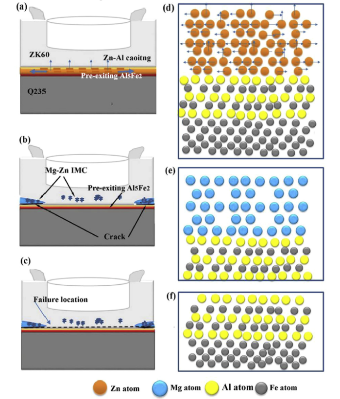
Based on the above analyses, the pre-existing ultra-thin Al5Fe2 IMC played a key role in joining Mg alloy and steel. Besides the large bonding area, there was a high bonding strength among Mg, Al5Fe2 and steel due to the formation of metallurgical bonding as shown in Fig. 5, Fig. 6, Fig. 7. To aid the following discussion a schematic diagram is presented in Fig. 11. First, the Zn-Al coating on the steel surface was melted due to the thermo-mechanical action of stirring tool as shown in Fig. 11(a). Second, a small amount of Zn diffused into the Mg substrate, and the majority of Zn was squeezed out of bonded region to the edge of the joint as shown in Fig. 11(a), (b) and (d). The crack was easily formed due to the slight deformation of Mg alloy substrate and low strength between Mg-Zn IMC and Al5Fe2 (Fig. 11(b)).
Fig. 11. Schematic of Zn-Al coating evolution of typical FSSW ZK60-steel joint: (a) movement of Zn-Al coating; (b) formation of joint; (c) failure location; (d) movement of Zn atom during FSSW; heterophase interfaces of (e) Fe2Al5/Mg and (f) Fe2Al5/Fe after FSSW.
Because the heat input was relatively low during the FSSW process, the Al-Fe phase which had a well-defined orientation relationship with Fe remained after FSSW due to its high melting point (Fig. 11(d)). Subsequently, Al5Fe2 as a transaction layer formed a heterophase interface with the Mg substrate (Fig. 11(f)). During tensile-shear test, the crack initiated at the edge zone of the joint. After initiation, the crack propagated along the interface between Mg and Al5Fe2 phase and resulted in failure at this interface (Fig. 11(c)).
In this study, Al-free ZK60 Mg alloy sheet and Zn-Al coated Q235 steel sheet was welded by FSSW, and the bonding mechanism among Mg-Al5Fe2-Fe was investigated. The following conclusions are drawn.
(1) The sound FSSW joint of ZK60 Mg alloy and Q235 steel was successfully realized with Al5Fe2 phase as the transition layer for promoting the metallurgical bonding of Mg-steel. The adoption of Al-free Mg alloy substrate further proved that the Al5Fe2 phase at the Mg-Fe interface came from the pre-existing Al5Fe2 phase in the coating.
(2) The interfaces with well-matched lattice sites among Fe, Al5Fe2 and Mg were formed during FSSW. A low energy interface with good match of lattice sites ((002)Al5Fe2//(110)Fe, [110]Al5Fe2//[$\bar{1}$13]Fe) was identified between Al5Fe2 and Fe. For the interface between Al5Fe2 and Mg, an orientation relationship of (6$\bar{2}$2)Al5Fe2//(3$\overline{122}$)Mgand[1$\overline{58}$]Al5Fe2//[2$\bar{4}$23]Mgwas observed.
(3) The tensile-shear load of FSSW ZK60-steel joint could reach 4.6 kN, which was superior or equivalent to that of the Mg-steel joints obtained by CMT, USW, or RSW techniques. The joint fracture occurred at the interface between the Al5Fe2 layer and the Mg alloy substrate, presenting the brittle fracture characteristic.
The research data has been uploaded to Mendeley Data.
This work was supported financially by the National Natural Science Foundation of China (Nos. 51601121, 51371179 and 51331008). Electron microscopy experiments were carried out at the Center for Microanalysis of Materials at the Frederick Seitz Materials Research Laboratory of University of Illinois at Urbana-Champaign, and supported by Department of Energy Basic Energy Sciences (No. DEFG02-01ER45923).

 WeChat
/
| 〈 |
|
〉 |


