Search for articles:
Thang Q. Tran , Jeremy Kong Yoong Lee
Corresponding authors:
Received: 2019-07-14
Revised: 2019-07-19
Accepted: 2019-08-6
Online: 2020-03-01
Copyright: 2020 Editorial board of Journal of Materials Science & Technology Copyright reserved, Editorial board of Journal of Materials Science & Technology
About authors:
1These authors are equally contributed to this work.
More
Abstract
In this study, we present a 2-step deposition method via sputtering and electroplating that uses carbon nanotube (CNT) wires synthesized from a wet-spinning technique to produce high-performance CNT/Au/Cu composite wires. After the Au sputtering pre-treatment, the deposition of Cu on the CNT wires was found to be much more homogeneous due to improved wettability and reactivity of the wire surface. At different electrodeposition time, the mechanical strength of the CNT/Au/Cu composite wires could be as high as 0.74 GPa (~ 2 times stronger than metal wires) while their electrical conductivity could reach 4.65 × 10⁵ S/cm (~ 80% of that for copper). More importantly, the CNT/Au/Cu composite wires with high CNT volume fraction are expected to be lightweight (up to 42% lower than Cu mass density), suggesting that our high-performance composite wires are a promising candidate to substitute conventional heavy metal wires in the future applications.
Keywords:
Since their discovery in 1991, carbon nanotubes (CNTs) have gained great attention in the scientific community due to their strong covalent carbon-carbon bonds and unique atomistic structures [1]. To transfer the superior mechanical, electrical, and thermal properties of the individual CNTs to real-life applications, high-performance macroscopic structures based upon CNTs, such as CNT wires [[2], [3], [4], [5]], CNT films [6] and CNT aerogels [7] have been developed. Among those assemblies, the CNT wires with aligned morphologies can better preserve the excellent anisotropic properties of the individual CNTs [8]. Therefore, they possess outstanding multifunctional properties and have great potential for a wide range of applications, such as structural reinforcements [9], flexible heaters [10,11], supercapacitors [12], lightweight electric cables [5,13] and medical devices [[14], [15], [16]].
CNT wires can be fabricated by two main approaches: dry-spinning from a CNT array [4] or a CNT aerogel [3,17] and wet-spinning from a CNT solution [2,5]. Due to the high contact resistance between individual CNTs and CNT bundles, the electrical properties of the CNT wires are much lower than those of the individual CNTs [8]. Several efforts have been made to enhance the electrical properties of the CNT wires. One approach is to optimize their synthesis processes to control the CNT wire morphologies such as CNT length, CNT wall number, CNT diameter, and CNT alignment [2,3,5,8]. The electrical performance of the CNT wires can also be improved by applying different post-treatments such as densification [17], purification [18] or introduction of extraneous materials [[19], [20], [21]]. Of these post-treatments, deposition of conductive metals such as silver, gold or copper on the CNT wires is one of the most widely used methods since they are simple but effective [[19], [20], [21]].
CNT/Cu composite wires with metallic electrical conductivity have become a promising lightweight candidate to replace conventional Cu wires in aerospace and automobile applications for fuel savings and CO2 emission cuts [[19], [20], [21]]. Electroplating Cu on CNT wires is an effective method to fabricate CNT/Cu composite wires with high flexibility to controlled composition and CNT alignment [22]. While most studies have applied this method to the CNT wires fabricated from dry-spinning methods with good CNT alignment and high CNT volume fraction [[19], [20], [21], [22]], the research on the electroplating treatment of the wet-spun CNT wires has not yet been studied. Since the wet-spun CNT wires have denser structure and better CNT alignment compared to the dry-spun wires [5], it would be expected that the electrodeposition of Cu on the wet-spun CNT wires could impact their electrical performance more significantly.
It is widely known that electrodeposition of Cu on pristine CNT wires is inhomogeneous due to differences in available active nucleation sites and the hydrophobic nature of the wires [22,23]. To enhance the electrochemical response of the CNT wires, several pre-treatment methods such as anodization [21,23,24], acidization [24], and heat treatment [23] have been applied to modify the CNT wire surface. These pre-treatments were found to enhance the wetting of the aqueous electrolyte and create a highly active surface suitable for homogenous electrodeposition [23,24]. While deposition of metal seed layer is one of the widely used pretreatment methods to improve the Cu electrodeposition on low conductive materials [22], very few studies of this method on the CNT wires are reported.
In this work, we aim to prepare CNT/Au/Cu composite wires by 2-step deposition via sputtering and electroplating. First, a thin layer of Au was sputtered on the surface of wet-spun CNT wires to improve its reactivity and wettability. Then, the Au-sputtered CNT wires were electrodeposited with Cu to produce the CNT/Au/Cu composite wires with high CNT volume fraction (Vf > 20%). The influences of electrodeposition time on the properties of the CNT/Au/Cu composite wires were discussed. The prepared composite wires were undergone microstructure investigations and electrical and mechanical property measurements.
The CNT wires used in this work were purchased from DexMat (USA), which were fabricated by wet-spinning method [5]. Sulfuric acid (ACS reagent 95%-98%) and copper (II) sulfate pentahydrate (98%) were purchased from Sigma-Aldrich (Singapore).
Au was deposited on the as-received CNT wires by using Sputter Coater 108auto (samples 6 cm away from the target, 20 mA, 10-2 mbar, 40 s, Cressington Scientific Instruments). Galvanostatic electrochemical deposition of Cu on the CNT wires was performed at room temperature in ambient conditions using an Autolab PGSTAT302 N (Metrohm Autolab, Netherlands) controlled by an Autolab software. Electrodeposition was conducted in a glass cell with a volume of 500 cm3 and its aqueous electrolyte consisted of copper sulfate (200 g/L) and sulfuric acid (40 g/L).
Fig. 1 shows the experimental setup for the Cu electrodeposition process with a standard two-electrode arrangement. The CNT wire was attached to a rigid PVC frame as the working electrode with current feed from the upper end of the wire via a copper tape (1181, 3 M Singapore Pte Ltd). Carbon tape (7311, Nisshin EM Co., Ltd, Japan) was used to form an electrical contact between the copper tape and the wire at the upper end while a 3 M scotch tape was used to attach the other end of the wire to the PVC frame. A piece of copper sheet was placed on one side of the wire to form an anode, which was connected to both counter and reference electrodes. The cathodic current was set at 0.15 mA while a series of deposition times, 0.5, 1.0, and 1.5 h, respectively, was performed to produce the composite wires with different Cu layer thickness.
Fig. 1. Experimental setup for electrodeposition of copper on CNT wire samples.
The diameter, structure, and morphology of the as-received CNT wires, Au-sputtered CNT wires, and CNT/Au/Cu composite wires were all characterized by an optical microscope (Leica DM2500 M) and a field emission scanning electron microscope (FE-SEM S4300, Hitachi). Energy dispersive X-ray spectroscopy (EDS) analyses were performed from the wire surfaces using scanning electron microscope (JEOL JSM-6010Plus/LV). To determine the diameter of the wires, we took measurements at more than 20 different positions along their lengths, which were then averaged. The CNT volume fraction of the CNT/Au/Cu composite wire was calculated by dividing the volume of the as-received CNT wire by the volume of the CNT/Au/Cu composite wire.
Tensile tests of all the wire samples were performed by an Instron 5943 tester equipped with an Instron 2530static load cell (50 N). The samples were sandwiched between two pieces of cardboard and clamped by micro-pneumatic grips. All samples were tested at a gage length of 10 mm with an extension rate of 1.2 mm/min [17]. The wire stress was determined by dividing the applied force by the wire cross-sectional area. The electrical resistance of the wires was measured by a 4-probe method using a Keithley 2450 SourceMeter [10]. The electrical conductivity of the wires was then determined by inverting their resistivity. All measurements were conducted on at least 5 samples to obtain the averages.
As specified by the manufacturer, the as-received CNT wires mainly consist of single-walled nanotubes (SWNTs) with high purity (~100%) and no traces of iron and carbonaceous materials. The typical CNT diameters are in the range of 1-2 nm [5]. Fig. 2(a) and (b) shows the images of the as-received and Au-sputtered CNT wires. As can be seen, the surface of the CNT wires turned from black to yellowish orange color after the sputtering treatment due to the Au coating. Both wires had similar diameters (~21.20 ± 0.37 μm), suggesting that Au-sputtering had no significant effects on the wire size.
Fig. 2. (a) As-received CNT wires, (b) Au-sputtered CNT wires, and (c) surface morphologies of the as-received CNT wires.
As shown in Fig. 2(c), the CNT wires consisted of aligned CNTs along the wires’ axis, which may stem from the flow-induced alignment effect of the wet-spinning process [8]. Very few pores observed in the CNT wire structure indicate that the wires possessed high packing density. In fact, their density was approximately 1.4 g/cm2, which was much higher than most of the dry-spun CNT wires [3,4,25]. Their highly dense structure may result from the densification effects caused by the coagulation process in the wet-spinning method using acetone as the coagulant [5].
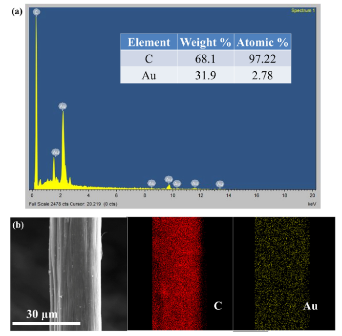
Fig. 3 shows the EDS analysis of the Au-sputtered CNT wires. As can be seen, the EDS spectrum confirms the successful deposition of Au particles on the CNT wires while their EDS mapping indicates that a uniform distribution of Au particles on surface of the CNT wires was achieved. The stress-strain curves of the as-received and Au-sputtered wires presented in Fig. 4(a) show similar behaviors and values, suggesting that the sputtering has no significant effects on the mechanical properties of the CNT wires. Due to the low fraction of Au deposited on CNT wires surface, the contribution of the Au layer to the mechanical performance of the resulting composite wires was negligible. However, the electrical resistance of the CNT wires increased slightly from 7.5 ± 0.28 Ω/cm to 8.2 ± 0.56 Ω/cm (Fig. 4(b)), corresponding to an approximately 8% reduction in their electrical conductivity after the pre-treatment. The lower electrical performance of the wires may stem from the fact that the CNT structure was bombarded with incident Au atoms of high kinetic energy during the sputtering process, resulting in the introduction of defects [26]. Besides, plasma-induced topological defects during the treatment may cause electron localization, which lowered the electrical conductivity of the wires [26]. The results are consistent with the lower electrical properties of the dry-spun CNT wires from CNT aerogel reported by Janas et al. [26] after their sputtering process with Au nanoparticles.
Fig. 3. (a) EDS spectrum and (b) elemental mapping of Au-sputtered CNT wires.
Fig. 4. (a) Stress-strain curves and (b) electrical properties of as-received and Au-sputtered CNT wires.
Fig. 5 presents the electrodeposition of Cu on the as-received and Au-sputtered CNT wires after 60 s. As can be seen in Fig. 5(a), Cu particles were deposited inhomogeneously on the surface of the as-received CNT wires in the first 30 s. Although the nuclei population density was higher and discrete Cu islands grew larger from the nucleation sites after 60 s deposition, no continuous Cu film was observed on the surface of the wires. This non-uniform deposition might be attributed to the differences both in the polarization and the number of available nucleation sites along the wire surface due to the inhomogeneous nature of the as-received CNT wires.
Fig. 5. SEM images and the insets showing the electrodeposition of Cu on (a) as-received CNT wires and (b) Au-sputtered CNT wires in 60 s.
Notably, deposition of Cu occurs preferentially at CNT surface defects [23] and, therefore, only the most active sites at the wire surface could become the sites for nuclei formation during the initial stage of the electrodeposition process. Additionally, the hydrophobic nature of the as-received CNT wires may limit the interaction between the wire surface and the aqueous copper sulfate electrolyte, leading to the non-uniform deposition of Cu on the CNT wires [22,23]. The findings are in good agreement with the inhomogeneous electrodeposition of Cu on the surface of the dry-spun CNT wires reported by Hannula et al [23].
However, the electrodeposition of Cu on the surface of the Au-sputtered CNT wires was more homogeneous, as shown in Fig. 5(b). After the first 30 s deposition, Cu particles were deposited on most of the wire surface with higher nuclei population density and smaller nuclei size compared to those formed in the as-received CNT wires. Interestingly, some discrete Cu islands grown from the nucleation sites could be observed along the wire surface. After 60 s deposition, the discrete Cu islands grew larger and coalesced together to form continuous Cu film. This result could be explained by the higher reactivity of the wire surface after the sputtering treatment. The thin and uniform layer of Au sputtered on the wire surface acted as homogeneous nucleation sites for the enhanced Cu deposition. Moreover, it has been reported that the deposition of Au onto CNT assemblies can make their surface much more hydrophilic [26]. Therefore, the electrolyte could wet the CNT wire surface completely, leading to the better Cu deposition process. These results are in good agreement with the improved Cu electrodeposition process of the dry-spun CNT wires pre-treated by heat treatment or anodization [23], suggesting that deposition of Au seed layer is an effective pre-treatment to improve the Cu electrodeposition of CNT wires.
3.3.1. Morphologies of the CNT/Au/Cu composite wires
Fig. 6 shows the SEM and optical images of the CNT/Au/Cu composite wires and compares their diameter and CNT volume fraction at different electrodeposition time. As shown in Fig. 6(a), the composite wires possessed a reddish brown color, which evidences the successful deposition of Cu on the wire surface. Their SEM image shown in Fig. 6(b) suggests that the CNT/Au/Cu composite wires had good uniform diameters with a slightly rough surface (Fig. 6(b)). With increasing deposition time, the wire diameter increased gradually from 21.20 ± 0.37 μm to 43.89 ± 0.56 μm, corresponding to a gradual decrease in their CNT volume fraction from 100% to 23%, as presented in Fig. 6(c). The increase in the wire diameter was due to the increasing amount of Cu deposited on the wire surface during the deposition process, which was determined by the applied current and electrodeposition time [20,27].
Fig. 6. (a) Optical image and (b) SEM image of the CNT/Au/Cu composite wires after 1.5 h Cu deposition and (c) diameter and CNT volume fraction of the CNT/Au/Cu composite wires at different electrodeposition time.
3.3.2. Electrical properties of the CNT/Au/Cu composite wires
Fig. 7 compares the electrical resistance and electrical conductivity of the CNT/Au/Cu composite wires at different electrodeposition time. As can be seen, the as-received CNT wires had a resistance and an electrical conductivity of 8.2 Ω/cm and 0.35 × 10⁵ S/cm, respectively. After 0.5 h deposition of Cu on the wire surface, the wire resistance dropped dramatically to 0.38 Ω/cm. Consequently, their electrical conductivity exhibited a significant increase by more than 10 times, reaching 3.64 × 10⁵ S/cm. The impressive improvement in the electrical properties of the wires could be attributed to the uniform deposition of Cu along the wire surface [20,21,27]. At longer deposition time, the thickness of the Cu layer increased, resulting in a further reduction in the wire resistance and a gradual increase in their electrical conductivity. Specifically, the electrical conductivity of the wires increased gradually from 3.64 × 10⁵ to 4.65 × 10⁵ S/cm when the deposition time increased from 0.5 to 1.5 h.
Fig. 7. Resistance and electrical conductivity of the CNT/Au/Cu composite wires at different electrodeposition time.
Due to the typical porous structure of the Cu shell formed by the electrodeposition process [28], a wide range of electrical conductivity is observed for the composite wires deposited at 0.5 and 1 h. At 1.5 h deposition, more conductive pathway might be created for electrons to move along the composite wires due to the deposition of thicker Cu layers, leading to their more consistent electrical conductivity and significant smaller error bar. The results are consistent with the improved electrical conductivity of the dry-spun CNT wires at different deposited Cu thickness [20,29].
3.3.3. Mechanical properties of the CNT/Au/Cu composite wires
Fig. 8(a) shows the stress-strain curves of the wire samples at different electrodeposition time. As can be seen, all the curves show a similar trend where a transition from elastic response to plastic deformation before failure is observed. The curves are linear and typically exhibit a sharp increase in slope at low strains (below 0.5%), and a gradual decrease in slope at higher strains, indicating that the tested wire samples had ductile behavior. Overall, the mechanical performance of the wire samples was significantly reduced with increasing deposition time.
Fig. 8. (a) Stress-strain curves, (b) tensile strength and stiffness and (c) cross-sectional area, tensile load, and elongation at failure of the CNT/Au/Cu composite wires at different electrodeposition time.
Fig. 8(b) reveals the mechanical performance of the wire samples at different electrodeposition time. The as-received CNT wires had an average tensile strength and stiffness of 1.19 GPa and 52.01 GPa, respectively. Their average elongation was 3.68%, suggesting that the wet-spun CNT wires had similar elongation range to the array-spun CNT wires but less flexible compared to the aerogel-spun CNT wires [17,25]. These results indicate that the as-received CNT wires had a fair mechanical performance, although their mechanical properties were in the range of the as-spun CNT wires reported in the literature [8]. This fair performance may result from the weak van der Waals interactions between the CNTs and CNT bundles, leading to the easy sliding of the CNTs and CNT bundles over each other [17,25]. The findings are supported by the large elongation at failure and the large plastic regions observed in their stress-strain curves.
In contrast to their electrical performance, the mechanical properties of the wire samples showed remarkable deterioration with increasing electrodeposition time. Specifically, after 0.5 h deposition of Cu, the strength and stiffness of the wire samples reduced to 0.74 and 46.74 GPa, respectively, corresponding to 62% and 90% of those of the as-received CNT wires. This significant reduction was evidently due mainly to the increase in the cross-sectional area of the wires from 353 to 667 μm2 after the Cu deposition although the maximum tensile load showed a slight increase from 0.42 N to 0.49 N, as presented in Fig. 8(c).
When the deposition time increased from 0.5 to 1.5 h, the cross-sectional area of the wires rose by 2.3 times (from 667 to 1541 μm2) whereas their bearing load only enhanced by 1.7 times (from 0.49 to 0.84 N). Therefore, their mechanical properties exhibited a gradual reduction, with decreases in strength from 0.74 to 0.55 GPa and in stiffness from 46.74 to 33.19 GPa. The reduction in the mechanical performance of the Cu-deposited wires was expected since the copper strength is low (0.2 - 0.3 GPa), and longer Cu deposition time would increase the weak fraction of the samples. The findings are in good agreement with the degradation in the mechanical performance with increasing Cu thickness of the dry-spun CNT wires deposited by physical vapor deposition [29] or electrodeposition method [20].
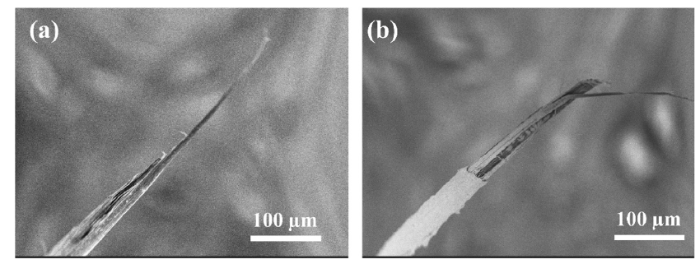
Fig. 9 shows the fracture morphology of the as-received and CNT/Au/Cu composite wires. As can be seen, the as-received CNT wires had long fracture length with several long pullout CNT bundles in the fracture surface due to the weak inter-tube interactions under tension. The CNT/Au/Cu composite wires, however, showed shorter fracture length and shorter pullout CNT bundles. These results are consistent with the reduction in elongation at failure of the wires after the Cu deposition treatment, indicating that the CNT/Au/Cu composite wires were less flexible than the as-received CNT wires. Although the CNT wires were pulled out from the copper layer, as presented in Fig. 9(b), the smooth stress-strain curves and improved tensile loads of the composite wires suggest that both core CNT wires and Cu deposited films might be load-bearing and break simultaneously.
Fig. 9. Fracture morphologies of (a) as-received CNT wires and (b) CNT/Au/Cu composite wires.
Fig. 10(a) compares the tensile strength and electrical conductivity of the CNT/Au/Cu composite wires in this work with several metals [5] and CNT/Cu composite wires fabricated from the dry-spun CNT wires without any post-treatments [[19], [20], [21]]. As can be observed, the mechanical strength of our composite wires was comparable to the CNT/Cu composite wires produced from the dry-spun CNT wires and about two times better than those of several metals such as Cu, Au, Al, Ni and Mg [5]. More importantly, the electrical conductivity of our composite wires was in the same order of magnitude as the pure Cu and other metals and much higher than most of the CNT/Cu composite wires based on dry-spinning methods [[19], [20], [21]]. Notably, the electrical and mechanical properties of the CNT composite wires can be improved further by applying different post-treatments such as rolling [19] or drawing [29]. Additionally, since our composite wires possessed high CNT volume fraction (23%-50%), they would be expected to have density lower than copper (up to 42% lower in mass density).
Fig. 10. (a) Comparison of the tensile strength and electrical conductivity of the CNT/Au/Cu composite wires in this work with several metals [
It is clear that there is a trade-off between electrical conductivity and mechanical strength of the CNT wires treated with Cu deposition process. Therefore, it is crucial to carefully design and optimize the Cu deposition thickness to tailor the wire performance for desired applications. Fig. 10(b) demonstrates the multifunctional properties of our CNT/Au/Cu composite wires by supporting and wiring a light-emitting diode lamp (LED, 50 g). The LED lamp was supported and connected to a Keithley 2450 source meter by two CNT/Au/Cu wires. The device could light up and its brightness can be tailored by adjusting the input current whereas the composite wires could withstand and transmit the electricity to the heavy lamp stably during the whole long test. Since our composite wires were lightweight with a reasonable combination of high strength and high electrical conductivity, they would become a very promising candidate to substitute heavy metal wires in the future applications.
In summary, CNT/Au/Cu composite wires were successfully synthesized by sputtering Au and electroplating Cu on the wet-spun CNT wires. The sputtered Au layer acted as a seed layer to improve the wettability and reactivity of the wire surface, resulting in enhanced homogeneity of Cu electrodeposition. Moreover, the electrical conductivity of the wires increased significantly to reach metallic performance although their mechanical strength deteriorated with increasing Cu layer thickness. At the CNT volume fraction of more than 20%, the composite wires were lightweight (up to 42% lower than Cu mass density) and possessed the combined properties of effective strength (~ 2 times more than that of the pure copper) and high electrical conductivity (up to 80% of that for pure copper). This work demonstrates that our CNT/Au/Cu composite wires have great potential to be the next-generation conducting materials for the future applications.
This work was supported financially by the Lloyd’s Register Foundation (No.R-265-000-553-597).

 WeChat
/
| 〈 |
|
〉 |


