Search for articles:
Kun Liu , Ming Liu
Corresponding authors:
Received: 2019-07-1
Revised: 2019-08-22
Accepted: 2019-08-28
Online: 2020-03-01
Copyright: 2020 Editorial board of Journal of Materials Science & Technology Copyright reserved, Editorial board of Journal of Materials Science & Technology
More
Abstract
Microstructural properties of spinel LiFe5O8 (LFO) films grown on (001)-oriented SrTiO3 (STO) substrates have been investigated at the atomic-scale by advanced electron microscopy techniques. Two types of orientation relationship (OR) between the LFO films and the STO substrates have been determined, cube-on-cube and (111)[$\bar{1}$ 10]LFO//(111)[1 $\bar{1}$ 0]STO. Antiphase boundaries (APBs) and three types of twin boundaries (TBs) form within the LFO films, and the propagation of TBs and APBs results in their complex interactions. In most cases, interactions between TBs and APBs change the type of TBs and terminate the propagation of APBs since the APBs introduce a displacement vector of (a/4)〈110〉 into the TBs. In addition, the interactions between two coherent TBs are observed to generate the incoherent TB. The epitaxial strain of the LFO/STO (001) heterosystem can be released by the formation of TBs and APBs in the films and misfit dislocations at the interface. Considering that the magnetic coupling across the APBs and TBs can lead to novel physical properties, the appearance of APBs and TBs with a high density in the LFO films would affect the magnetic properties of the films.
Keywords:
The ferromagnetic lithium ferrite has recently attracted considerable attention of research due to its high saturation magnetization, high Curie temperature, large electric resistivity, low loss at high frequencies, and good chemical stability [[1], [2], [3]]. The abundant physical properties make it a promising candidate for potential applications in spin filtering and microwave devices [4,5]. For novel device applications, spinel-typed materials in the form of thin films are highly desired [[6], [7], [8], [9], [10], [11], [12]]. So far, different thin-film deposition processes and techniques have been applied to fabricate high-quality LiFe5O8 (LFO) films [11,[13], [14], [15]].
Planar defects, e.g., antiphase boundary (APB) [16,17] and Ruddlesden-Popper (RP) faults [18], could form in the ferromagnetic films, which effectively affect the general properties of the films. Therefore, the properties of the films could be tuned by controlling the formation of these defects in the films [[19], [20], [21], [22], [23], [24]]. For instance, APBs are widely present in spinel ferrite films, e.g., Fe3O4 [25], NiFe2O4 [22], and LFO [16]. Antiferromagnetic coupling occurs across the APB, which leads to non-saturation of magnetization and larger magnetoresistance of the ferromagnetic film. In addition, twin boundaries (TBs), were observed in spinel-type materials, e.g., Fe3O4 [26] and CoFe2O4 [27], which induce the abnormal magnetic properties. Moreover, it was reported that the formation of TBs in spinel-type films (e.g., NiFe2O4) depends on the type of the substrates [28]. Concerning magnetic coupling across the TBs, Chen et al. reported that ferromagnetic or antiferromagnetic properties of TBs in Fe3O4 are related to the structure details of the TBs, e.g., the antiferromagnetic coupling across the non-stoichiometric TBs [29]. To date, the atomic structure of TBs in other ferromagnetic spinel ferrites is rarely reported. Additionally, compared with ferromagnetic spinel films prepared on the substrates, e.g., MgO [30,31] and MgAl2O4 [16,[32], [33], [34]], the film-growth behavior and microstructural properties (e.g., crystallographic orientation relationship (OR) and growth defects) of the spinel films prepared on perovskite-type substrates remain unclear.
In the present work, film-growth behavior and atomic-scale microstructural properties of spinel LFO films prepared on (001)-oriented SrTiO3 (STO) substrates have been investigated by aberration-corrected scanning transmission electron microscopy (STEM). The film-substrate OR and the relaxation of epitaxial strain have been determined in the LFO/STO (001) system. Atomic-scale structure of TBs and APBs, and the complex interactions between the planar defects have been characterized using atomic-resolution high-angle annular dark-field (HAADF) and annular bright-field (ABF) imaging techniques [35,36].
The LFO ceramic target for film growth was prepared by a standard solid-state reaction method with the initial reactants Fe2O3 and LiCO3 (ratio 5:2) [15]. The LFO films were grown on single-crystalline STO (001) substrates by a high-pressure sputtering system at the substrate temperature of 800 °C and under 0.5 mbar of the mixed ambient of Ar and O2 at the ratio of 1:1.
Cross-sectional lamella specimens for TEM/STEM investigation were prepared by focused ion beam (FIB) lift-out technique using an FEI Helios600i Dualbeam system. The lamellae were cut in STO 〈110〉 and 〈100〉 orientations. Bright-field (BF) TEM images and selected-area electron diffraction (SAED) patterns were obtained on a JEOL JEM-2100 microscope. Atomic-resolution HAADF and ABF images were acquired on a JEOL ARM200F with a probe aberration corrector, operated at 200 kV. In STEM mode a probe size of 0.1 nm at semi-convergence angle of an α = 22 mrad was used for HAADF and ABF imaging experiments. The HAADF and ABF detectors covered angular ranges of 90-176 mrad and 11-22 mrad, respectively.
Fig. 1(a) displays a low-magnification cross-sectional BF-TEM image of the LFO/STO (001) heterostructure, recorded along the [1 $\bar{1}$0] zone axis of the substrate, showing the overview of the heterostructure. The film-substrate interface can be clearly distinguished by the contrast difference, as marked by a horizontal white arrow. The thickness of the film was determined to be about 35 nm. In the film, oblique fringe lines parallel to the {111} planes of the film can be observed, as indicated by oblique red arrows, which originate from the planar defects. These defects start at film-substrate interface, and in most cases, penetrate the whole film thickness. The density of the defects is estimated to be about 9 × 10⁵/cm in the film.
Fig. 1. (a) Low-magnification BF-TEM image of a LFO film on STO (001) substrate. The film-substrate interface is indicated by a horizontal white arrow. The oblique fringe lines are denoted by red arrows. (b) Typical SAED pattern of the LFO/STO (001) system, recorded along the [1 $\bar{1}$ 0] STO zone axis. The splitting of the reflection spots is indicated by the horizontal and the vertical arrows. (c) High-resolution HAADF image of the heterostructure showing the existence of two types of OR between the film and the substrate, viewed along the [1 $\bar{1}$ 0] STO zone axis. The TB is indicated by an oblique red arrow. The film-substrate interface is indicated by a horizontal white arrow.
A typical SAED pattern shown in Fig. 1(b) was acquired from a film-substrate interface area where the LFO/STO (001) heterostructure is defect-free and recorded along the [1 $\bar{1}$ 0] zone axis of the substrate. A (001)[1 $\bar{1}$ 0]LFO//(001)[1 $\bar{1}$ 0]STO (or cube-on-cube) OR between the film and the substrate can be concluded on the basis of analysis of the SAED pattern. The splitting of the diffraction spots between the film and the substrate is clearly visible, marked by horizontal and vertical arrows in Fig. 1(b), which indicates that relaxation of the epitaxial strain occurs in the heterostructure. Taking the lattice parameter of STO (aSTO = 0.3905 nm [37]) as a calibration standard, the in-plane and the out-of-plane lattice parameter of the LFO film was calculated to be 0.830 ± 0.005 nm and 0.836 ± 0.004 nm, respectively. In the diffraction investigation, no other additional diffraction spots were observed in the patterns, implying that no secondary phase formed in the films.
Fig. 1(c) shows an atomic-resolution HAADF image of the LFO/STO interface, recorded along the [1 $\bar{1}$ 0] zone axis of the substrate. The film-substrate interface is atomically sharp, as indicated by a horizontal arrow. The film contains two domains (I and II) showing a twin relationship. The TB is parallel to the {111} planes in both domains, as marked by an oblique red arrow. As can be seen from the image, the domain I grows epitaxially on the substrate with a cube-on-cube OR, while the OR between the domain II and the substrate can be determined as (111)[$\bar{1}$ 10]LFO//(111)[1 $\bar{1}$ 0]STO. In fact, two types of OR were also observed from SAED patterns (see Fig. S1 in Supplemental materials).
Fig. 2 displays an atomic-resolution HAADF image of the LFO/STO interface, recorded along the [1 $\bar{1}$ 0] zone axis of the substrate, showing the existence of misfit dislocations and interfacial dislocations bound to an APB at the interface. Performing a Burger circuit around the isolated misfit dislocation core leads to a projected displacement vector of (a/4)[110], where a is the lattice parameter of LFO (a ≈ 2aSTO). The atomic-structure of the APBs in LFO has been discussed in our previous work [16]. It is noted that the edge-on APBs bound to interfacial dislocations produce the same projected displacement vector as the isolated misfit dislocations, as shown by the Burger circuit on the right part of Fig. 2. It is necessary to mention that in the LFO film, apart from the (a/4)[110]-typed APBs, inclined APBs with a displacement vector of (a/4)[011] or (a/4)[101] were also observed.
Fig. 2. High-resolution HAADF image of the film-substrate interface, viewed along the [1 $\bar{1}$ 0] STO zone axis, showing the formation of misfit dislocations and an APB at the interface. The APB is indicated by a vertical white arrow. The film-substrate interface is denoted by a horizontal white arrow.
In the LFO/STO(001) heterostructure, the in-plane lattice mismatch between the film and the substrate is calculated to be about 6.2% using the formula [(a - 2aSTO)/2aSTO] × 100% and the lattice parameters of bulk STO and LFO [37,38]. The lattice mismatch with a positive sign implies that the compressive stress is introduced to the film while the LFO film coherently grows on the STO substrate. In fact, apart from misfit dislocations, APBs bound to interfacial dislocations also contribute to the film-substrate strain relaxation. In addition, the relatively large lattice mismatch in the LFO/STO (001) heterostructure leads to the formation of TBs. In fact, in other heterostructures, it was also observed that the epitaxial strain could be partially released by the formation of microtwin lamellae in the films [[39], [40], [41], [42]].
Three types of TB (referred as TB-I, TB-II and TB-III) were observed in the film, which are shown in the HADDF images of Fig. 3(a-c), respectively, recorded along the [1 $\bar{1}$ 0] zone axis of the film. In Fig. 3(a), the red dashed lines denote the Fe[Li0.5Fe1.5]O2 atomic plane in the domain I and II that are separated by the TB-I, indicated by a green arrow. It can be seen that across the TB-I the domains I and II are in a reflection symmetry. In contrast, in Fig. 3(b) and (c), the domains I and II separated by either a TB-II or a TB-III are in a glide-reflection symmetry that is a combination of a reflection and a translation. The TB in Fig. 3(b) and (c) is indicated by a white and a red arrow, respectively. It should be mentioned that the translational vector for the two domains is different. Fig. 3(d) shows the ABF image of TB-III simultaneously acquired with the HAADF image in Fig. 3(c). Under the ABF imaging condition, the oxygen columns are visible. Considering that under the HADDF imaging conditions the atomic-column intensity is approximately proportional to Z2, where Z is the atomic number averaged in the atomic columns [43], a (111) plane with cation deficiency can be detected in Fig. 3(c), as denoted by a red arrow. The cation deficiency in the atomic columns induces the intensity variation at the TB. In Fig. 3(c) and (d) the orange arrow demonstrates the atomic column with cation deficiency. The structure of the TB-III in the LFO film observed in the present study agrees with the nonstoichiometric TB in Fe3O4 [29]. It should be mentioned that the TB-III was frequently observed in the LFO film. In contrast, the number of the TB-I and TB-II is dominant in the Fe3O4 single crystal.
Fig. 3. (a, b) Atomic-resolution HAADF image of the LFO film containing TB-I and TB-II, respectively, recorded along the [1 $\bar{1}$ 0] LFO zone axis. The TB-I is indicated by an oblique green, and the TB-II by an oblique white arrow. The red dashed lines denote the Fe[Li0.5Fe1.5]O2 atomic plane. (c, d) Atomic-resolution HAADF and ABF image of TB-III, recorded simultaneously along the [1 $\bar{1}$ 0] LFO zone axis. The cation-deficient plane is marked by oblique red arrows. The atomic column with cation-deficiency is indicated by orange arrows. The red dashed lines denote the Fe[Li0.5Fe1.5]O2 atomic plane.
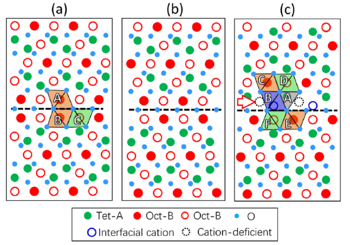
To further clarify the atomic arrangement at the TBs observed in the LFO film, the schematic models of TBs in spinel AB2O4 are displayed in Fig. 4(a-c), projected along the 〈110〉 zone axis of AB2O4. Along the viewing direction, the density of cation at the octahedral sites (B-sites) is different. To illustrate this difference, the density of cation columns represented by red solid circles is two times as high as that of the columns represented by red circles. On the basis of the HAADF images (in Fig. 3(a) and (b)) and the corresponding ABF images (Supplementary Fig. S2), the oxygen sublattice in both TB-I and TB-II shows a feature of Σ3{111} coherent TBs. The twin planes of the Σ3 TBs are marked by black broken-lines in Fig. 4(a) and (b). In contrast to edge-sharing octahetra in perfect AB2O4 lattice, across the TB-I and TB-II, both face-sharing and corner-sharing octahedra coexist. For instance, across the TB-I in Fig. 4(a), the octahedra share face (e.g., octahedra A and B) and corner (e.g., octahedra A and C).
Fig. 4. (a-c) The structure model of TB-I, TB-II and TB-III, respectively, viewed along the [1 $\bar{1}$ 0] LFO zone axis. The twin plane is marked by a black dashed line. In (c), the atomic plane with cation-deficiency is indicated by a horizontal red arrow. Cation-deficient sites are marked by black dashed circles.
For the TB-III, the oxygen sublattice is likely to maintain the feature of the Σ3{111} coherent TBs, as marked by a black broken-line in Fig. 4(c). There are cation-deficient sites close to the TB-III, as marked by black dashed circles. The atomic plane with cation deficiency is denoted by a horizontal red arrow. The A-site cations adjacent to this atomic plane are still in tetrahedral sites (e.g., tetrahedron A). In contrast, the cations marked by blue circles adjacent to this atomic plane are in octahedral sites (e.g., octahedron B). The tetrahedra (e.g., tetrahedron A) share corners with neighboring octahedra. Additionally, the octahedra (e.g., octahedron B) share corner with neighboring octahedra (e.g., octahedra E and F) and edge with other neighboring octahedra (e.g., octahedra C and D). It is worth noting that there are no tetrahedra adjacent to the twin plane in the TB-I and TB-II, except for the TB-III.
Both TBs and APBs appear in the LFO/STO system. The propagation of these planar defects results in the complex interactions. Fig. 5(a) shows an atomic-resolution HAADF image containing the interactions between TBs and APBs, taken along the [1 $\bar{1}$ 0] zone axis of the film. The TB-I and TB-III are indicated by a green and a red arrow, respectively. Along the viewing direction, the APB is edge-on with a displacement vector of (a/4)[110], as marked by a yellow arrow, which separates the TB-I from TB-III. A triple junction of TBs and APB is marked by an ellipse. Importantly, the appearance of the APB alters the type of the TBs, which means TB-I and TB-III can transform each other by introducing an (a/4)[110] displacement.
Fig. 5. Atomic-resolution HAADF image showing the complex interaction between TBs and APBs, recorded along the [1 $\bar{1}$ 0] LFO zone axis. (a) Interaction of APBs with TB-I and TB-III. (b) Interaction of APBs with TB-II and TB-III. (c) Interaction of APBs with TB-I and TB-II. In (a-c), APBs are indicated by a yellow arrow and the triple junctions are marked by ellipses. TB-I, TB-II and TB-III are indicated by a green, a white and a red arrow, respectively.
In Fig. 5(b), TB-II and TB-III are shown, as denoted by a white and a red arrow, respectively. It should be noted that the TB-II and the TB-III are also separated by an APB. The triple junction is marked by an ellipse. Along the viewing direction, the APB is not edge-on and shows a blurred contrast due to the overlap between domains I and II (see Supplementary Fig. S3 for further details), as indicated by a yellow arrow. The APB could have a displacement vector of either (a/4)[101] or (a/4)[011]. The intersection of the APB at the TBs alters the type of TBs. In Fig. 5(c), an inclined APB is marked by a yellow arrow, which leads to a blurred contrast due to the overlaps of two domains (I and II) adjacent to the APB. A displacement vector of the APB could be either (a/4)[101] or (a/4)[011]. It can be seen that TB-I and TB-II, indicated by a green and a white arrow, respectively, are separated by the APB. An ellipse indicates the triple junction of the TBs and APB. Similarly, TB-I and TB-II can transform each other by the displacement vector of the inclined APB. It is worth mentioning that in Fig. 5(a)‒(c), APBs could not prevent the propagation of TBs, but change the type of TBs. In contrast, TBs terminate the propagation of the APBs in the film.
Occasionally, the interactions between TBs and APBs could not stop the propagation of TBs and APBs, as shown in the high-resolution HAADF image in Fig. 6, viewed along the [1 $\bar{1}$ 0] zone axis of the film. A thin twin lamella and the APBs are denoted by red arrows and yellow arrows, respectively. Both TBs of the twin lamella are type of TB-III. The interactions with the APBs do not change the type of the TBs but introduce a relative displacement into the TBs. Accordingly, a shear displacement occurs within the twin lamella, which divides it into two parts (I and II). Their boundary is marked by a white dashed line, which connects with the APBs, as marked by yellow dashed lines. It is noted that the displacement vector is (a/4)[110] for the TBs, which fits to that of the APBs.
Fig. 6. Atomic-resolution HAADF image showing the interaction of a thin twin lamella with APBs, recorded along the [1 $\bar{1}$ 0] LFO zone axis. TBs and APBs are indicated by oblique red and vertical yellow arrows, respectively. A boundary within the thin twin lamella resulting from the shear displacement is marked by a white dashed line, which connects with the APBs, as marked by yellow dashed lines.
The propagation of TBs in the {111} plane can lead to the interactions between TBs in the LFO film. In fact, the interactions of TBs in metals of fcc structure have been studied [[44], [45], [46], [47]], while rarely reported in the spinel oxides. Fig. 7(a) displays an atomic-scale HAADF image containing the TB interactions, viewed along the [1 $\bar{1}$ 0] zone axis of the film. It can be seen that two TBs-III locate in the (111) and ($\bar{1}$$\bar{1}$ 1) plane, respectively, as indicated by oblique red arrows. The TBs-III separate the film area into domains I, II and III. It is noted that the domains I and II have a twin relationship. The interaction of two TBs-III leads to the formation of an incoherent TB, as indicated by the vertical yellow arrow. The incoherent TB is parallel to the (110) plane of the domain III. The intensity variation can be discerned at the incoherent TB, which indicates that cation deficiency may exist at the TB. A schematic model of the interaction of the two TBs-III is displayed in Fig. 7(b). The coherent TBs-III are indicated by red arrows and the incoherent TB is covered in light blue. Unfortunately, it is difficult to establish the atomic structure of the incoherent TB on the basis of the HAADF image due to the blurred contrast and the irregularity of atomic arrangement at the boundaries.
Fig. 7. (a) Atomic-resolution HAADF image of the LFO film showing that the interactions of coherent TBs produce incoherent TB. The triple junction is marked by an ellipse. The red dashed lines denote the Fe[Li0.5Fe1.5]O2 atomic plane. (b) A schematic model of the interaction between two TBs-III. The incoherent TB is marked in blue. In (a) and (b), the coherent TBs are indicated by red arrows, and the incoherent TB is indicated by a yellow arrow.
In the LFO/STO(001) heterostructure, the relatively large lattice mismatch (~6.2%) between LFO and STO results in the formation of LFO nuclei with two types of OR with the STO substrate. In the case of the cube-on-cube OR in the heterostructure, the coalescence of neighboring nuclei can result in the formation of APBs in the film, which also occurs in the LFO/MgAl2O4 and Fe3O4/MgO heterostructure [16,17]. In contrast, the coalescence of neighboring nuclei with different types of OR can lead to the formation of TBs in the film. It should be mentioned that the formation of APBs, TBs and misfit dislocations contributes to the strain relaxation in the heterostructure.
On the basis of experimental results, the configuration of the oxygen sublattice is the same for the different types of TB in LFO. Therefore, the structure of these three types of TB can be transformed by translation vectors to shift the cation sublattice across the TBs. To illustrate the relationship of the TBs, a structure model projected along the [1 $\bar{1}$ 0] zone axis of AB2O4 is displayed in Fig. 8. The Σ3{111} TBs of the oxygen sublattice are indicated by a black dashed line. The upper parts display the relationship of the three types of TB. Applying a translation vector to the cation sublattice of the upper parts of the TBs introduces the transformation of the TBs. In fact, the transformation between TB-I and TB-II can be realized by one of the following displacement vectors (ar/4)[1- 01] = (ar/8)[11- 2] + (ar/8)[1- 10], (ar/4)[01- 1] = (ar/8)[11- 2] + (ar/8)[11- 0], (ar/4)[101-] = (ar/8)[112-] + (ar/8)[11- 0], or (ar/4)[011-] = (ar/8)[112-] + (ar/8)[1- 10] (ar is the lattice parameter of AB2O4). The transformation between TB-I and TB-III can be achieved by introducing a translation vector (ar/4)[110] (or (ar/4)[11- 0]) into the cation sublattice. Accordingly, the translation vector between TB-II and TB-III can be obtained by adding the translation vector corresponding to the transformation between TB-I and TB-III to that corresponding to the transformation between TB-I and TB-II, e.g., (ar/4)[011] = (ar/4)[1- 01] + (ar/4)[110]. It is known that in the spinel structure the appearance of the {110}(ar/4)〈110〉-type APBs does not disturb the oxygen sublattice, but interrupt the stacking sequence of the cation sublattice [16,17]. As a result, the interaction between the {110}(ar/4) 〈110〉-type APBs and TBs induces the transformation of different type TBs in the LFO film and the termination of APBs at the TBs.
Fig. 8. Structure model of the relationship among TB-I, TB-II and TB-III. The twin plane of oxygen sublattice is indicated by a horizontal black dashed-line. The atomic plane with cation-deficiency in the TB-III is marked by a horizontal red arrow.
It is known that the magnetic spins align antiparallel between the tetrahedral and the octahedral sites in the spinel structure AB2O4 (e.g., Fe3O4) [3]. Across the APBs, the antiferromagnetic coupling occurs in the spinel, e.g., LFO [16] and Fe3O4 [17]. Across the TBs, the magnetic coupling should directly depend on the structure of the TBs [29]. The magnetic coupling across the TBs in LFO can be either ferromagnetic (TB-I) or antiferromagnetic (TB-II and TB-III) since the atomic structure of TBs in the LFO film is similar to that in Fe3O4. Our results show that the density of the TB-III is much higher than that of the TB-I and TB-II in the LFO film, which is different from the case of the Fe3O4 single crystal. The phenomena may result from the different synthesis methods and chemical composition between these two materials. Considering the magnetic coupling across APBs and TBs in LFO, the nano-scale TBs, in addition to APBs, may have promising applications in nano-spintronic devices, e.g., spin torque magnetic random access memory [9,25,48].
Using aberration-corrected STEM, the microstructure properties of LFO film prepared on (001)-oriented STO substrate have been investigated at the atomic scale. The findings are summarized as follows.
(1) Two types of OR, cube-on-cube and (111)[$\bar{1}$ 10]LFO//(111)[1 $\bar{1}$ 0]STO, have been determined between the LFO film and the STO substrate.
(2) TBs and APBs form in the LFO film, which contribute to the epitaxial strain relaxation in the LFO/STO (001) heterostructure.
(3) Three types of TBs have been characterized at the atomic scale. Across these TBs, the oxygen sublattices show a feature of Σ3 coherent TBs and the cation sublattices are in the relationship of either reflection symmetry or glide-reflection symmetry.
(4) The interactions between TBs and APBs can alter the type of TBs and terminate the propagation of APBs. The interactions between two coherent TBs form the incoherent TBs.
It is believed that the existence of a high density of APBs and TBs within the LFO films would influence their physical properties (e.g., magnetoresistance).
The work was financially supported by the National Basic Research Program of China (No. 2015CB654903) and the National Natural Science Foundation of China (Nos. 51471169 and 51390472).
Supplementary material related to this article can be found, inthe online version, at doi:https://doi.org/10.1016/j.jmst.2019.08.039.

 WeChat
/
| 〈 |
|
〉 |


