Search for articles:
Xu Wang , Nan Zhang
Corresponding authors:
Copyright: 2019 Editorial board of Journal of Materials Science & Technology Copyright reserved, Editorial board of Journal of Materials Science & Technology
More
Abstract
Large size, high-density (99.97%) and well-organized Al2O3/Y3Al5O12 (YAG) eutectic ceramics were prepared by the modified Bridgman method. The evolution of the three dimensional microstructure and micropores were investigated. The diameter of the micro-pores and the porosity decreased during directional solidification. The average equivalent diameter of the micro-pores was 2.41 μm in the well-prepared eutectic ceramics. Most of the pores (98.07%) were smaller than 4 μm. These data are comparable to those prepared by the optical floating zone method. The as-grown eutectic ceramics were polycrystalline, but the interfaces were well-bonded and there were no amorphous phases in the microstructure. The misfits of the different crystallographic relationships were calculated, and the bottleneck of the single-crystal preparation was identified. These results could provide theoretical guidance for the preparation of large, single-crystal Al2O3/YAG eutectic ceramics by the modified Bridgman method.
Keywords:
Directionally solidified eutectic ceramics, such as Al2O3/Y3Al5O12 (YAG) [[1], [2], [3]], Al2O3/GdAlO3 [4,5], Al2O3/YAG/ZrO2 [6,7] and Al2O3/ZrO2 [8,9] have recently been studied in depth to tailor their properties for use at high temperatures. Directionally solidified ceramics show excellent flexural strength, improved flaw tolerance and superior resistance to creep, oxidation and abrasion at elevated temperatures, and are considered to be potential high-temperature structural materials [10,11].
Various directional solidification (DS) methods, such as the laser floating zone method [5,12], edge-defined film growth method [13], micro-pulling-down method [14], and optical floating zone (OFZ) method [3,15], have been used to fabricate directionally solidified Al2O3/YAG eutectic ceramics. These techniques usually have high thermal gradients ($\widetilde{1}$03 K/cm) [16]. The as-grown samples can grow at higher withdraw rates ( m/h) [16]. Unfortunately, only small (mm-scale or even μm-scale) samples can be obtained. The size is limited by the stability of the floating zone or meniscus. The small size imposes restrictions on their use as structural materials. Fortunately, the Bridgman method is generally used to prepare large-scale eutectic ceramics [17]. The sample size can be as large as the crucible size. However, this technique has a lower thermal gradient (20-40 K/cm) [14,18]. The withdraw rate must be very low (on the scale of mm/h). In fact, large Al2O3/YAG or Al2O3/GdAlO3 eutectic ceramics have successfully been prepared by the Bridgman method [13,19,20]. As is known, the grain boundary (GB) is a weakness factor in materials used at high temperatures. As a potential high-temperature material, Al2O3/YAG eutectic ceramic should be prepared in single-crystal (SX) form (there are no GBs). Nevertheless, it is not easy to fabricate SX of Al2O3/YAG eutectic ceramics without a grain selector of complex shape, such as the pigtail-shaped spiral used to prepare nickel based SX superalloy [21]. In the previous study, SX of Al2O3/YAG eutectic ceramics have been grown with the OFZ method after a growth distance of $\widetilde{8}$0 mm at a low growth rate of 20 mm/h [22]. The purpose of the present study is to prepare SX Al2O3/YAG eutectic ceramics by the modified Bridgman method with a molybdenum crucible. Inspired by research based on the OFZ method, a molybdenum crucible is designed with a selection tube at the bottom, because molybdenum is difficult to cut. The mold has a grain selection tube with a length of 90 mm and a diameter of 9 mm at the bottom. The necking is also designed to further eliminate the disoriented grain(s).
The excellent high-temperature strength of Al2O3/YAG eutectic ceramics is mainly ascribed to its inherent characteristics, including well-bonded interfaces and unique, three-dimensional interpenetrated structures [18,23]. Actually, the micropores are important parts, degrade the properties of the ceramics. In previous studies, the SX of Al2O3/YAG eutectic ceramics prepared by the OFZ method showed high density, and a porosity of only 0.013% [24]. In the present study, the as-prepared eutectic ceramics are contained in a molybdenum mold. The content and distribution of the micropores remain unknown.
To solve these issues, the microstructure of an Al2O3/YAG eutectic ceramic during solidification was investigated. The three-dimensional microstructure and the micropores were observed by X-ray computed tomography (XCT). The crystallographic information was studied with the electron backscattered diffraction (EBSD) technique. The interface structure was studied by high-resolution transmission electron microscopy (HRTEM). The results may shed light on preparing SX of Al2O3/YAG eutectic ceramics.
Al2O3 and Y2O3 powders were mixed and ball-milled for 12 h at a mole ratio of Al2O3:Y2O3 = 79:21 according to the eutectic composition. Then, the raw materials were packed into a rubber sleeve with PVA as media and kept at 350 MPa for 45 min to improve the density, and were then put into the molybdenum mold. The dimension of the crucible was 45 mm × 120 mm × 20 mm.
DS was conducted in a modified Bridgman furnace, which contained a heating zone and a cooling zone. More details of the modified Bridgman furnace can be found in our previous work [3]. The vacuum level rose to 10-3 Pa at 2273 K. For comparison, the withdraw rate was 20 mm/h, equal to that of the OFZ method. After the temperature had been maintained at 2273 K for 30 min, the DS began. The as-cast Al2O3/YAG eutectic ceramic is show in Fig. 1.
Fig. 1. Mo mold and the as-cast Al2O3/YAG eutectic sample (a) and (b); (c) Al2O3/YAG eutectic sample after annealing at 1550 °C for 48 h.
The as-cast Al2O3/YAG eutectic ceramics were sectioned into two parts by a diamond endless wire saw. The samples were ground with SiC paper and polished with diamond paste to 1.5 μm. The microstructure was observed by scanning electron microscopy (SEM), (LEO, SUPRA 35, Ammerbuch, Germany). The crystallography was investigated by EBSD (NordlysNano, Oxfordshire, UK). Thin-foil specimens for the HRTEM (FEI Tecnai G2 F20, Oregon, USA) investigation were prepared by slicing the specimens, mechanically grinding them to $\widetilde{2}$5 μm, and ion beam-milling them at 5.0 kV. A 200 kV TEM was used for investigation of the interfaces and the HRTEM observation. A fast Fourier transformation (FFT) was carried out with the Digital Micrograph package (Gatan, California, USA). The three-dimensional microstructure was investigated by the XCT with the lab-based X-radia 500 Versa XRM system (Zeiss, Germany).
Fig. 1(a) shows the as-cast Al2O3/YAG eutectic ceramics. The DS experiment was conducted in vacuum environment. The as-cast Al2O3/YAG eutectic ceramic is black in color because of the oxygen vacancy. It reverts to gray/white after annealing at 1500 °C for 48 h, as exhibited in Fig. 1(b) and (c). This phenomenon is different from that reported in our previous work, in which the as-cast Al2O3/YAG eutectic ceramics prepared by the seeding technique reverted to completely white with the same treatment process [3]. The difference may be due to the GB structure. The Al2O3/YAG eutectic ceramic obtained in the present work may be polycrystalline (PX).
The microstructure evolution during DS was studied. Fig. 2(a) and (b) shows the microstructure at the bottom and top of the grain selection bar, respectively, marked by the white rectangle. The light gray is the YAG phase and the dark gray is Al2O3 phase. At the beginning of the DS, the YAG dendrites can be observed. Competitive growth of the dendrites and eutectic is apparent. According to the Jackson-Hunt model [25], the formation of the YAG dendrites may be due to the high G/V value (low temperature gradient G and the relatively high solidification rate V). The growth of the YAG is disordered. However, with continued DS, the YAG dendrites disappear and the eutectic microstructure can be observed, as exhibited in Fig. 2(b). Fig. 3 shows the longitudinal microstructures of four representative parts of the directionally solidified Al2O3/YAG eutectic ceramics. The eutectic microstructure is complexly irregular and is usually referred as Chinese Script.
Fig. 2. Longitudinal microstructures at the top (a) and bottom (b) of the grain selection bar (marked by the white rectangles).
Fig. 3. Longitudinal SEM images of four representative sections of the as-cast Al2O3/YAG eutectic ceramics.
Fig. 4 shows the three-dimensional microstructure in the area marked by the white rectangle in Fig. 2(b). The light gray area is the YAG phase, and the dark gray area is Al2O3 phase. The eutectic microstructure is not homogeneous. The YAG size is much larger than that of Al2O3 (because of the limited resolution ratio of the XCT technique, the secondary arm spacing of the YAG phase cannot be observed). This result agrees well with that obtained by the SEM. Fig. 5 shows the three-dimensional microstructure in the area marked by the white rectangle in Fig. 2(a). It can be seen that the microstructure is well organized. The YAG and Al2O3 interpenetrate into each other and exhibit the classical Chinese Script microstructure.
Fig. 4. (a) Constructed three-dimensional microstructure in the area marked by the white rectangle in
Fig. 5. (a) Three-dimensional microstructure in the area marked by the white rectangle in
Micropores cannot be eliminated in directionally solidified Al2O3/YAG eutectic ceramics, which degrade their properties. The spatial distribution and the size of the micropores were investigated. Fig. 6(a) shows the distribution, size and the frequency of the micropores in the zone marked by the white rectangle in Fig. 2(b). It can be observed that the micropores are irregularly shaped, and some of them extend along the growth direction. Their distribution is concentrated. The maximum diameter is 34 μm. 11.3% of micropores have diameters larger than 4 μm. The porosity is 0.44%. Furthermore, Fig. 6(b) shows the micropores characterization in the zone marked by the white rectangle in Fig. 2(a). The micropores are highly dispersed. Most of them (98.07%) are smaller than 4 μm. The average equivalent diameter is 2.4 μm, which equals to that (2.6 μm) prepared by the OFZ method [24]. The porosity is only 0.033%, being slightly larger than that (0.013%) obtained by the OFZ method [26]. The parameters of the micropores of the two representative parts of the as-cast Al2O3/YAG eutectic ceramics are summarized in Table 1.
Fig. 6. Micro-pores and their spatial distribution in the area marked by the white rectangle in
Table 1 Parameters of the micropores of the two representative parts, together with the previously reported values for comparison.
| Methods | Maximum diameter (μm) | Average equivalent diameter (μm) | Frequency (d < 4 μm) | Porosity |
|---|---|---|---|---|
| Bridgman (Fig. 4) | 34 | 3.71 | 88.7% | 0.44% |
| Bridgman (Fig. 5) | 12.8 | 2.41 | 98.07% | 0.033% |
| OFZ [22] | 11.5 | 2.6 | 84% | 0.013% |
This study aims to prepare SX of Al2O3/YAG eutectic ceramics by the modified Bridgman method without a specially-shaped grain selector or seed. Fig. 7(a) shows the microstructure of the as-grown Al2O3/YAG eutectic ceramics observed by transverse optical microscopy. The as-grown Al2O3/YAG eutectic ceramics are P X . The GBs can be observed due to their photo‐absorption anisotropy of the grains. The microstructure is divided into five parts according to contrast. The five parts are numbered from I to V. To clarify, the crystallography is investigated, and the corresponding EBSD maps are exhibited in Fig. 7(b-f). It can be seen that both the YAG and Al2O3 show different crystallographic relationships. They are P X . SX of Al2O3/YAG eutectic ceramics does not form. What is worthy of mention is that these crystallographic relationships are very different from the reported preferred crystallographic relationship (marked as CR1) of < $\bar{1010}$ > {0001} Al2O3 || <110> {211} YAG [13,22]. This preferred crystallographic relationship was reported to have the lowest interfacial energy [16,26]. For comparison, the interface structure marked by the red arrow in Fig. 7(b) was investigated, as shown in Fig. 8. No amorphous phases can be observed between the YAG and Al2O3, and compatible interfaces are formed. The crystallographic relationship (marked as CR2) is: <0001 > { $\bar{1120}$}Al2O3 || <001 > {420}YAG. In addition, the interfaces shown in Fig. 7(d) and (e) with low index are also taken into account (interfaces shown in Fig. 7(c) and (f) with higher index are not considered). The crystallographic relationships are: < $\bar{1010}$ > {0001}Al2O3 || <112 > {011}YAG (CR3) and < $\bar{1120}$ >{0001}Al2O3 || <011 > {211}YAG (CR4), respectively.
Fig. 7. (a) Transverse optical microscopy photograph in the area marked by the white rectangle in
Fig. 8. Transverse sectional TEM micrograph of the Al2O3/YAG interface indicated by the red arrow in
Fig. 9 shows the schematic illustration of interfaces and interfaces matching for the cases of CR1, CR2, CR3, and CR4. Based on the Bramfitt equation [27], the two-dimensional lattice misfit of the two matching planes can be calculated as:
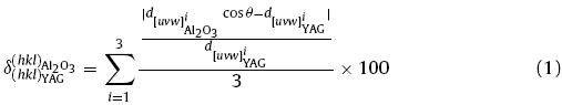
Fig. 9. Schematic illustration of interfaces and interface matching of case I: <0001 > { $\bar{1120}$}Al2O3 || <001 > {420}YAG (a); case II: < $\bar{1010}$ >{0001}Al2O3 || < 112 > {011}YAG (b), case III: < $\bar{1120}$>{0001}Al2O3 || <110 > {211}YAG (c); and case IV: < $\bar{1010}$ > {0001} Al2O3 || < 110 > {211} YAG (d); Corresponding lattice structures of the four cases are given beside the matching images.
The misfits of these crystallographic relationships are summarized in Table 2 (detailed calculation information can be found in Table S1). The misfit of CR4 is 8.4%, smaller than that of the others, which implies that CR4 possesses the lowest interfacial strain energy. Therefore, one can conclude that the grain selection process has not been finished and requires a longer growth distance to form SX.
Table 2 Crystallographic relationships and the corresponding misfits between Al2O3 and the YAG.
| Case | Misfit (%) |
|---|---|
| I: <0001 > { $\bar{1120}$}Al2O3 || <001 > {420}YAG | 10.4 |
| II: < $\bar{1010}$ >{0001}Al2O3 || <112 > {011}YAG | 9.8 |
| III: < $\bar{1120}$ >{0001}Al2O3 || <110 > {211}YAG | 11.9 |
| IV: < $\bar{1010}$ > {0001}Al2O3 || < 110 > {211}YAG [20] | 8.4 |
SX of Al2O3/YAG eutectics were successfully prepared by the OFZ method [22] but preparation failed with the modified Bridgman method. The main difference between the two methods is the temperature gradient (the withdraw rates were both 20 mm/h). The temperature gradient is $\widetilde{1}$500 K/cm for the OFZ method [16] and 20-40 K/cm [18] for modified Bridgman method. According to classical solidification theory [28], thermal gradient is calculated by dividing the cooling rate (C, K/s) by the solidification rate (V, cm/s): G = C/V (K/cm). Since it is not possible to directly measure the solidification-front velocity, it is assumed to be equal to the withdrawal rate (R, cm/s) [28]. In spite of the equivalent withdrawal rate of the two methods, the growth dynamic condition of the modified Bridgman method is much harsher than that of the OFZ method. Therefore, longer growth distances or slower withdrawal rates are required when preparing SX of Al2O3/YAG eutectic by the modified Bridgman method. However, it is notable that the as-prepared Al2O3/YAG eutectic ceramics have a well-organized eutectic microstructure and high density (99.697%) although it is P X .
In summary, large size, high-density, and well-organized Al2O3/YAG eutectic ceramics have been prepared by the modified Bridgman method. The evolution of three-dimensional microstructure and micropores have been investigated. The average equivalent diameter of the micropores in the well-prepared eutectic ceramics is 2.41 μm and most of the pores (98.07%) are smaller than 4 μm. The preparation of the SX of Al2O3/YAG eutectic ceramics by the modified Bridgman method without a grain selector of complex shape has not been achieved. The misfits of the different crystallographic relationships have been calculated and the reasons for the failed preparation of the SX preparation have been identified.
This work was financially supported by the National Natural Science Foundation of China (Nos. 51804252 and 51701156), the Equipment Pre-Research Foundation of China (Nos. 6140759040102 and 6140923040203) and the Doctoral Starting Fund of Xi’an University of Technology (No. 101-451116013).
The authors have declared that no competing interests exist.

 WeChat
/
| 〈 |
|
〉 |


