Search for articles:
Received: 2019-02-14
Online: 2019-09-20
Copyright: 2019 Editorial board of Journal of Materials Science & Technology Copyright reserved, Editorial board of Journal of Materials Science & Technology
More
Abstract
Keywords:
Metal additive manufacturing technologies of electron beam melting (EBM), laser melting deposition (LMD) and selective laser melting (SLM) have attracted attentions in industry because of their ability to integrally build metal parts with complex shapes [[1], [2], [3], [4]]. During building, repetitive processes of depositing a thin layer of powders and then being selectively melted by electron beam or laser to bond with the substrate or the already solidified material below are applied. Therefore, the manufactured parts would experience a distinctive heat history involving unsteady reheating and cooling cycles due to line- and layer-wise melting and solidification [5,6]. This heat history makes EBM, LMD and SLM processes inherently possess a huge potential for in-situ regulating microstructure to achieve desired mechanical properties, which is termed as intrinsic heat treatment (IHT) [7].
Compared with LMD and SLM, EBM’s IHT is unique because the temperature of powder bed can be elevated and maintained above 1000 °C [8], which is commonly used to improve the microstructure of alloys to a large extent. For example, many types of enhanced precipitations occur in EBMed Inconel 718 [8,9] and the decomposition of martensite forms in EBMed Ti6Al4V [10]. LMD’s IHT consists of sharp temperature pulses close to the melting point [11], and it also can be used to improve properties by triggering in-situ aging precipitation or clustering atoms in different alloys such as Maraging steels [11] and Inconel 718 [12]. Comparatively, the IHT of SLM is considered more complex for the following features: (a) much higher heating and cooling rates ($\widetilde{1}$03-108 K/s) can be achieved [13] due to the small size of molten pools and effective heat conduction by the underlying layers and substrate; (b) a shorter residence time (in millisecond level) of heating is generated as the laser passes by the previous deposited metal [14] due to high scanning speeds and non-high temperature preheating; (c) the number of thermal cycles during SLM can be serveral orders of magnitude greater than that of LMD. Rapid solidification of SLM usually results in finer microstructures and an enhanced solute trapping [15], which may make in-situ aging precipitation or clustering atoms be easier. On the contrary, the short residence time of heating in SLM is not conducive to the aging precipitation or clustering atoms. Therefore, it is currently unclear whether the IHT of SLM can produce in-situ aging precipitation or clustering atoms.
Inconel 718 alloy, a typical precipitation hardened superalloy [16,17], is widely applied in the aerospace fields such as gas turbine and combustion chamber though its hard processability. However, SLM presents a great opportunity to improve the efficiency in processing this kind of material [18]. In practice, post heat treatment is necessary for SLMed Inconel 718 parts to improve microstructure and mechanical properties further [19,20] though lower production efficiencies. Besides, for some SLMed thin-wall components, subsequent heat treatment usually leads to deformation. If the IHT of SLM can trigger the precipitation of strengthening phases in situ, it is possible to reduce or even avoid the subsequent heat treatment for Inconel 718 components to realize high efficiency and energy saving.
Therefore, for the first time, we directly confirmed the precipitation of strengthening phases by in-situ aging during SLM. More interestingly, the stepwise precipitation of strengthening phases with multiple types in SLMed Inconel 718 can be realized by governing thermal cycles. Besides, the mechanism of stepwise precipitation derived from the IHT during SLM is revealed.
The SLM experiments were carried out on a self-developed machine (LSNF-2), whose details have been described in our previous publication [21]. The used gas atomized Inconel 718 powders are spherical with an average diameter of 32.7 μm. The nominal chemical composition (wt %) of the powders is 0.56 Al, 1.01 Ti, 18.94 Cr, 0.01 Mn, 53.23 Ni, 3.0 Mo, 4.98 Nb, 0.04 C, and Fe (balance). A series of single-layer with 1-16 tracks and single-track walls with 1-40 layers were designed and fabricated using the SLM processing parameters shown in Table 1.
Table 1 SLM processing parameters applied in experiments.
| Group | Laser power, P (W) | Layer thickness, T (μm) | Scanning speed, V (mm/s) | Hatch spacing, S (μm) |
|---|---|---|---|---|
| Single-layer | 350 | 40 | 1000 | 80 |
| Single-track wall | 350 | 40 | 1000 | - |
All SLMed specimens were polished and then electrolytically etched in a mixture of 70 ml H3PO4 and 30 ml H2O at 5 V for 90 s. Afterwards, microstructures of all samples were characterized using an optical microscope (OM) and a FEI Nova Nano 450 scanning electron microscope (SEM). A focused ion beam (FIB) technique was applied to make thin foils of the single-layer and single-track samples. Then, the thin foils were analyzed by a FEI Tecnai G2 F30 transmission electron microscope (TEM) equipped with an energy dispersive spectrometer (EDS). Vickers hardness tests on cross sections of the single-layer and single-track samples were also carried out with a HVS-1000 microhardness tester at a load of 0.98 N.
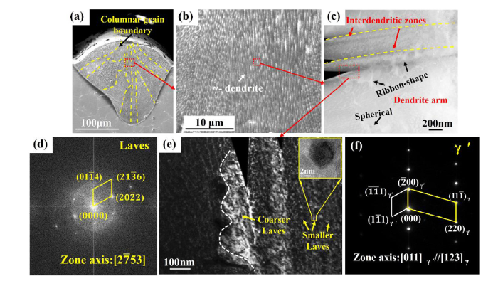
Fig. 1(a) shows the morphology of the molten pool with a depth and width of $\widetilde{1}$50 μm and $\widetilde{2}$50 μm, respectively. The columnar grains grow inclined to the centerline of molten pool, i.e. the negative direction of heat flow. Fig. 1(b) and (c) show the enlarged views of tiny columnar grains. The spacing of γ-dendrites can be measured to be about 0.5 μm. It can also be observed that many ribbon-shape Laves (Cr2Nb) phases (confirmed by the FFT in Fig. 1(d)) are formed in the interdendritic zones. In Fig. 1(e), the widths of Laves phases are about several to dozens nanometers, which are much smaller than those in EBMed and LMDed Inconel 718 [9,12], implying that the atomic solid solubility of the SLMed γ-matrix is greatly increased. Besides, it is interesting that a small number of spherical γ′ (Ni3Al) phases (confirmed by the SAED in Fig. 1(f)) with a diameter of $\widetilde{5}$0 nm are observed in the dendrite arm. Obviously, during SLM solidification process, atomic groups are increased to serve as nucleation sites for γ′ phases, which is completely different from the LMDed Inconel 718 where γ′ phase is not formed. Thus, the large atomic saturation and abundant atomic groups in the matrix provide great possibilities for the precipitation of strengthening phase in the subsequent thermal cycles during SLM.
Fig. 1. SEM and TEM results of the single molten pool: SEM images (a and b) are obtained from the XOZ section; (c) is the TEM image of precipitates; (d) and (e) are the FFT and dark-field images of Laves phase, respectively; (f) is the SAED result of the γ′ phase.
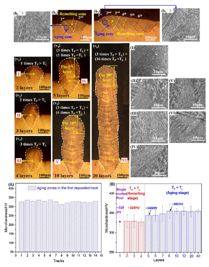
The track-by-track melting and solidification of metal powders yield SLM horizontal thermal cycles. Fig. 2(h1) and (h2) give the microstructures of SLMed single-layer samples with two and six tracks, respectively. As the next track is deposited, the previously solidified molten pool is divided into remelting zone and aging zone by comparing the laser peak temperature (TP) and the liquidus temperature (TL). If the TP exceeds TL, the remelting zone forms, otherwise the aging zone forms. For the first track, it will experience one time remelting and multiple aging treatments caused by the subsequent depositions. Compared with the single molten pool in Fig. 1(b), no significant dendrite difference in aging zone of the first track is found after one time and 5 times of horizontal thermal cycles (Fig. 2(h1´) and (h2´)). Besides, as shown in Fig. 2(A), the microhardness in the aging zone of the first track shows no obvious change with increasing times of horizontal thermal cycles, which corresponds with the trend of the microstructures observed above.
Fig. 2. Cross-sections of SLMed single-layer samples (h1 and h2) and single-track walls (v1-v6); h1´ and h2´ are the magnifications of the boxed areas in h1 and h2, respectively; I-VI are the microstructural magnifications in the first deposited layer of single-track walls under various heights; (A) and (B) are the variation trends of microhardness in the first deposited track of the single-layer samples and single-track walls, respectively.
Multiple consolidated tracks are metallurgically bonded along the building direction to produce vertical thermal cycles (Fig. 2(v1)-(v6)). Thus, the previous several solidified tracks of the single-track wall are remelted along the building direction when depositing a new track. The maximum remelting time (nr) depends on the following formula (1): nr=⌊dpT⌋, where dp is the penetration depth of molten pool and T is the layer thickness. In this experiment, the real penetration depth is as high as $\widetilde{1}$80 μm judged by the final layer in Fig. 2(v4)-(v6), suggesting that nearly 4 previous deposited layers are remelted for each laser radiation according to formula (1). Therefore, for single-track walls with less than or equal to 4 layers in height, the first deposited layer will undergo 1-3 times of vertical thermal cycles with TP > TL (Fig. 2(v1)-(v3)). Once over 4 layers, 3 times of vertical thermal cycles with TP > TL and multiple vertical thermal cycles of TP < TL will be applied to the first deposited layer (Fig. 2(v4)-(v6)).
Fig. 2(I)-(VI) show the γ-dendrites in the first deposited layer of single-track walls under various heights. Clearly, compared with the single molten pool ($\widetilde{0}$.5 μm), there is no significant change in primary dendrite arm spacing as nr increases from 1 to 3 (Fig. 2(I)-(III)). Similarly, constant values of the primary dendritic arm spacing are maintained when applying different times of vertical thermal cycles with TP < TL (Fig. 2(IV)-(VI)), which is similar to the result under horizontal thermal cycles.
But, unlike the aging effect during horizontal thermal cycles, the microhardness values in the aging zones during vertical thermal cycles show a tendency to rise first and then to flatten out, as shown in Fig. 2(B). Compared with the microhardness values ($\widetilde{3}$25 HV) in the single molten pool and remelting zone, the microhardness values increase from $\widetilde{3}$45 HV to $\widetilde{3}$60 HV as the times of vertical thermal cycle with TP < TL increase from 1 to 4. However, the microhardness remains $\widetilde{3}$60 HV even though more thermal cycles of TP < TL are applied. Clearly, this significant change in microhardness is not associated with the size of dendrites but the strengthening phases.
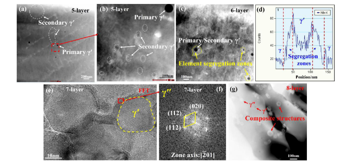
Fig. 3(a) shows the dendritic substructures of the first deposited layer in the single-track wall with 5 layers. After undergoing one time of thermal cycle with TP < TL, the sizes of γ′ phase have changed. Except for the primary γ′ with a large size formed in single molten pool, some secondary γ′ phases ranging from several to a dozen nanometers precipitate from the matrix, as marked by white circles in Fig. 3(a) and (b). Hence, the SLM vertical thermal cycles of TP < TL can serve as an aging treatment to preferentially precipitate γ′, which results in the microhardness increasing from $\widetilde{3}$25 HV to $\widetilde{3}$45 HV in the first deposited layer. When two times of vertical thermal cycles with TP < TL are applied (Fig. 3(c)), with the growth of γ′, some element segregation zones around γ′ were found. EDS indicates that these zones are rich in Nb elements (Fig. 3(d)), which can improve the driving force of γ″ (Ni3Nb) nucleation. Subsequently, when the times of vertical thermal cycle with TP < TL go up to 3, some composite sandwich structures (Fig. 3(e)) with primary/secondary γ′ coated by a γ″ shell (indicated by the FFT image in Fig. 3(f)) can be observed. As the times of vertical thermal cycles of TP < TL increase to 4, except for the γ′ phases and composite phases, a few γ″ phases also precipitate from the γ-matrix (Fig. 3(g)), which should be ascribed to the fact that the actual temperature in the first deposited layer is lower than the precipitation temperature of strengthening phase (Tpre). These multiple strengthening phases improve the microhardness of the first deposited layer to $\widetilde{3}$60 HV. Therefore, in-situ precipitation of strengthening phases should meet the following temperature condition: Tpre <TP < TL, where the Tp is associated with SLM processing parameters including laser power, scanning speed and layer thickness. To sum up, the SLM vertical thermal cycles of Tpre <TP < TL can act as the aging treatment to promote the stepwise precipitation of three types of strengthening phases including γ′, composite phase and γ″.
Fig. 3. TEM results of the strengthening phases in the first deposited layer of single-track walls with 5-layer (a and b), 6-layer (c and d), 7-layer (e and f) and 8-layer (g).
During the deposition process of thin walls in this experiment, the precipitation and growth of strengthening phases were completed only after applying four times of vertical thermal cycles with Tpre <TP < TL. The duration of thermal cycles is in the order of millisecond, which belongs to a multi-times and short-term aging treatment, far less than the LMDed aging time with an order of second [12].
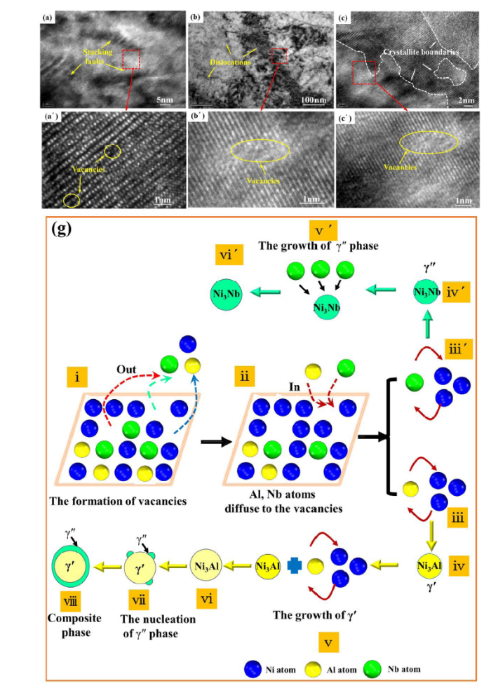
Fig. 4(a)-(c) and (a´)-(c´) show the substructures of γ-matrix in the single molten pool. A high density of stacking faults (Fig. 4(a)), dislocations (Fig. 4(b)), and crystallite boundaries (Fig. 4(c)) caused by rapid cooling rates during SLM can be observed in the matrix. Under a high resolution (Fig. 4(a´)-(c´)), a large number of vacancies form in these lattice defects mentioned above. The presence of vacancies will lead to the distortion of electronic density at each atom site, improving the internal energy of the crystal [22]. When applying the thermal cycles of Tpre <TP < TL, some high energetic atomic groups in the matrix overcome the binding of surrounding atoms and migrate to other locations due to energy fluctuation, leading to the formation of vacancies in the original equilibrium position. Meanwhile, these vacancies will be filled with single atom. It is well known that the vacancy formation energies of Al, Ni, and Nb increase successively [23]. Moreover, based on the first-principles of density-functional calculations and atom probe tomography, the diffusion rates of Nb, Al, Ni atoms decrease successively [24].
Fig. 4. Under a high resolution (a´-c´), a large number of vacancies form in stacking faults (a), dislocations (b), and crystallite boundaries (c) of the γ-matrix in the SLMed Inconel 718 molten pool; (g) is the schematic diagram of precipitation and growth of γ′, composite phase and γ″.
Therefore, based on the differences of vacancy formation energy and diffusion rates of solute atoms, the precipitation and growth mechanisms of strengthening phases are discussed, as shown in Fig. 4(g). When one time aging treatment is applied, Al atoms can migrate to vacancies more easily compared with Ni atoms (Fig. 4(g) i and ii). The Al atoms and Ni atoms cluster together to form the core of γ′ (Fig. 4(g) iii and iv). Based on diffusion theory, the diffusion rates of solution atoms in solid can reach 1 nm per millisecond due to the fact that the temperature near the boundary of each molten pool can approach the melting point [25]. Moreover, the fast channel network composed of vacancies accelerates the diffusion rates of solid atoms, which can greatly promote the growth of γ′ (Fig. 4(g) v and vi). However, the size of γ′ is small at this moment (Fig. 3(b)), which should be attributed to the higher cooling rates [15]. For the growing γ′, an ordered face centered cubic (FCC) structure, Al solute atoms locate at the cube corners. While for γ″ phase, Nb solute atoms occupy the center and corners of a cell, which seems like to put one fcc cell upon the other. So, the growing γ′ can provide potential nucleation sites for the body-centered tetragonal γ″. In addition, the vertical thermal cycles can act as a solution treatment to release Nb atoms from nanoscale Laves phases [20], which makes Nb atoms gather around γ′ (Fig. 3(c)) to improve the driving force of γ″ nucleation. Therefore, γ′ can easily be wrapped by γ″ to form a composite phase (Fig. 4(g) vii). The growth of peripheral γ" mainly depends on the diffusion of Nb atoms dissolved from the Laves phase (Fig. 4(g) viii).
But for Nb atom, although its diffusion rate in the matrix is faster than that of Al atom, it’s very difficult to combine with Ni atom to form γ″ due to the fact that the incoherent precipitation between γ″ and matrix needs a greater phase-transformation activation energy. Thus, compared with γ′, the formation of γ″ requires more times of SLM vertical thermal cycles with Tpre <TP < TL (Fig. 4(g) iii´ and iv´), which is consistent with the observed results (Fig. 3). The growth of γ″ also relies on the supply of Nb atoms (Fig. 4(g) v´ and vi´). For the growing γ′, its elastic interaction energy with the matrix hinders the formation of γ″. However, once γ″ begins to form, the release of elastic interaction energy can be induced to promote the subsequent growth of γ″ [26]. Therefore, the composite phase is easier to precipitate from the matrix than γ″. In addition, with the laser away, the slower cooling rate is conducive to the growth of strengthening phases [15] (Fig. 3(g)).
In summary, a stepwise precipitation of strengthening phases with multiple types and an increased microhardness are achieved in SLMed Inconel 718 alloy during in-situ aging. The key to realize step-by-step precipitation is adjusting the types and times of SLM thermal cycles. Vertical thermal cycles of Tpre <TP < TL are more effective in promoting precipitation than horizontal thermal cycles. The sequential precipitation of γ′, composite phase of the primary/secondary γ′ coated by a γ″ shell, and γ″ occurs as the times of vertical thermal cycles with Tpre <TP < TL increase. Finally, short-term aging mechanisms on different strengthening phases are explored based on a great number of vacancies in the γ-matrix. This work demonstrates the possibility to precipitation strengthen producing parts in situ by the IHT of SLM.
This work was financially supported by the National Natural Science Foundation of China (No. 50905068) and the China Postdoctoral Science Foundation funded projects (Nos. 2017M620317 and 2018T110759). The authors would like to thank the Analytical and Testing Center of Huazhong University of Science and Technology. And Special thanks to Mr Jianquan Zhao for the TEM operation.
The authors have declared that no competing interests exist.

 WeChat
/
| 〈 |
|
〉 |