Search for articles:
Yang Shen
Corresponding authors:
Received: 2018-12-5
Revised: 2019-01-18
Accepted: 2019-02-1
Online: 2019-08-05
Copyright: 2019 Editorial board of Journal of Materials Science & Technology Copyright reserved, Editorial board of Journal of Materials Science & Technology
More
Abstract
Microstructure features of 12MnNiVR pressure vessel steel welded joint deposited by the high heat input electrogas welding have been systematically investigated. It is revealed that the welded joint is featured by a heterogeneous juxtaposition. The coarse grained heat-affected zone (CGHAZ) primarily consists of lath bainites and minor granular bainites. The fine grained heat-affected zone (FGHAZ) is dominated by polygonal ferrites, pearlites, and fine cementite particles. Moreover, electron backscatter diffraction results further demonstrate that the CGHAZ is populated by coarse prior austenite grains (PAGs) with high frequency (61.3%) of low angle grain boundaries (LAGBs). On the other hand, the FGHAZ is filled with fine PAGs with a lower frequency (19.6%) of LAGBs. Such microstructural differences may likely contribute to differed mechanical properties for samples tested at designed positions.
Keywords:
Statistics of International Energy Agency (IEA) indicates that the consumption of oil and derivatives rises steadily in recent decades. Concurrently, crude oil, as an important strategic material, has become a stringent issue concerning all countries. With increasing volume of strategic petroleum reserve, it requires the construction of large scale crude oil storage tanks, which necessitate thick steel plates [[1], [2], [3]]. In practice, fusion welding techniques are usually indispensable in the fabrication of such large pressure vessel structures. Thick steel plates are generally joined by a multi-pass welding process, for instance, submerged arc welding (SAW) and flux-cored arc welding (FCAW) [[4], [5], [6]]. However, to further enhance construction efficiency and reduce welding cost, electrogas welding (EGW), a continuous vertical position one-pass welding process, has gained extensive engineering momentum [7].
12MnNiVR steel is a heavy section grade with superior mechanical properties such as high strength, good impact toughness, and excellent weldability under high heat input of up to 100 kJ/cm [8]. Over the years, it has been widely applied in large oil storage tanks [9]. One-pass EGW with high heat input is commonly practiced to join 12MnNiVR steel. Due to excessive high heat input, EGW treatment may likely lead to significant coarsening of austenite grains and formation of brittle microstructures such as ferrite side plate (FSP), upper bainite (Bu) and coarsening grain boundary ferrite (GBF), ushering inferior performance of welded joints [[10], [11], [12], [13], [14]].
Extensive studies have been done on high-strength low-alloy (HSLA) steel in the past decade to clarify the correlation of microstructure and mechanical properties of heat-affected zone (HAZ). Yang et al. [8] demonstrated, for the 610 MPa grade high-strength steel, the microstructure of the coarse grained heat-affected zone (CGHAZ) evolved from bainite to polygonal ferrite, acicular ferrite, and suggested that toughness is dictated by the volume fraction of M-A constituent. Lambert et al. [15] revealed the correlation between toughness and microstructure of simulated HAZ using a Gleeble 1500 thermal-mechanical simulator and discovered brittle M-A constituents at the origin of cleavage cracking. Zou et al. [16] reported that the nucleation and growth behaviors of ferrite laths in HAZ of EH36-Mg shipbuilding steel with different heat inputs. It is noted that most of studies are concentrated on specific regions such as CGHAZ by using Gleeble thermodynamic simulator, instead of actual welding process [17,18]. Moreover, few reports are focused on the entire welded joints. Sun et al. [19] investigated the microstructure and mechanical properties of HSLA steel weldment after vibratory electrogas arc welding. It is well known that welding thermal cycles generate a heterogeneous microstructure in HAZ of the butt-welded steel plate, which is divided into CGHAZ and fine grained heat-affected zone (FGHAZ) by the peak temperature [20]. However, till now, little is known about the heterogeneous microstructures and mechanical properties of 12MnNiVR steel welded joints, which can offer a fundamental understanding on the welded joints failure during service.
In the present work, the heterogeneous microstructures of the welded joints in 12MnNiVR steel plate produced by using direct quenching and tempering right after the one-pass EGW with high heat input were investigated systematically by scanning electron microscopy (SEM) and electron backscatter diffraction (EBSD). The main purpose of this work is to illuminate the microstructural evolution of the welded joints, and to clarify the correlation between the microstructure and mechanical properties. It is found that the degradation of the toughness and strength in the CGHAZ is probably due to the coarse prior austenite grain size and the high frequency of low angle grain boundaries (LAGBs).
12MnNiVR pressure vessel steel was used as the base metal. The slab was hot rolled to 23 mm thick plate, directly quenched at 1033 K, and subsequently tempered at 913 K for 80.5 min. Two nominally identical as-received steel plates with dimensions of 500 mm in length (welding direction) and 200 mm in width (rolling direction) were welded together using the EGW with a 34° Y weld groove. The chemical compositions of 12MnNiVR base metal and EGW filler metal DW-S60 G (1.6 mm in diameter) are listed in Table 1. EGW parameters applied for the filling pass were 360 A DC, 36 V, 8.4 cm/min welding speed, and 92.6 kJ/cm heat input. The shielding gas was pure CO2 (27 L/min).
Table 1 Chemical composition of 12MnNiVR base metal and EGW filler metal DW-S60 G (wt%).
| Materials | C | Si | Mn | P | S | Ni | Cr | Mo |
|---|---|---|---|---|---|---|---|---|
| Base metal | 0.1 | 0.19 | 1.5 | 0.006 | 0.0012 | 0.27 | 0.05 | 0.13 |
| DW-S60G | 0.08 | 0.32 | 1.67 | 0.010 | 0.008 | 0.71 | 0.03 | 0.25 |
The positions of the test specimens are illustrated in Fig. 1. For microstructure characterization, cross-section specimens were cut from the as-welded 12MnNiVR joints. These specimens were prepared by standard metallographic procedures. Samples were mechanical ground, polished, and chemically etched with 4% nital. A field-emission scanning electron microscope (FESEM, SU8010, Hitachi, Japan) under 20.0 kV acceleration voltage was employed to reveal microstructure. Moreover, crystallographic features were revealed using EBSD. Samples with a size of 10 mm × 5 mm × 0.5 mm were sectioned from the welded joint. After conventional mechanical grinding and polishing, the specimen surface was subjected to electropolishing using an electrolyte of the solution of perchloric acid and ethanol with the volume ratio of 1:20. The operating voltage, duration and temperature were 35 V, 36 s and 293 K, respectively. A detailed description of locating CGHAZ and FGHAZ is depicted in Ref. [21]. EBSD mappings were obtained using FESEM (JSM-7800 F, JEOL, Japan) operated at 20.0 kV with the sample stage tilted by 70° fitted with NordlysNano detector (Oxford Instruments) and HKL CHANNEL5 software. The size of mapping area was 459 × 459 with 0.1 μm step of a regular square grid. The input lattices for electron back scattered patterns (EBSP) indexing were ferrite (body-centered cubic structure with lattice parameters a ∼2.87 Å and a I\bar${m}$3m space group).
Fig. 1. Schematic diagram of as-welded 12MnNiVR weldment showing positions where specimens for desired tests are taken.
Mechanical properties were determined via microhardness, Charpy impact, and tensile tests. Vickers hardness across the cross-section of the polished and etched welded joint specimen was measured with a 0.2 kgf, a dwell time of 10 s, and an indentation spacing of 150 μm with the straight lines themselves separated by a distance of 1 mm by using a microhardness tester (HXD-1000TMC/LCD, China).
Charpy impact specimens were machined from 5 different locations into standard V-notch samples with dimensions of 10 mm × 10 mm × 55 mm, with the V-notch axis of specimen perpendicular to the welding direction. The V-notch positions of the impact specimens are designed at the center of the fusion line (FL), 0.5 mm outside of the FL, 1 mm outside of the FL, 2 mm outside of the FL, 3 mm outside of the FL, respectively, which are referred as FL0, FL0.5, FL1, FL2, and FL3, respectively. For each position, three samples were prepared and the average value of three tests were reported. Such specimens were subjected to impact tests on a pendulum impact testing machine (SANS-ZBC2452-C, MTS, U.S.A.) at 258 K.
Full thickness tensile specimen with dimensions of 100 mm in parallel length and 37 mm in width were cut from the as-welded plate with longitudinal axis parallel to the rolling direction and the weld metal in the middle of the tensile specimen. Tensile tests were performed at room temperature using a 500 kN tensile testing machine (AG-I, Shimadzu, Japan). Fractured surfaces of the broken Charpy impact test and tensile test specimens were characterized using an FESEM (Ultra Plus, ZEISS, Germany) to determine the fracture mode.
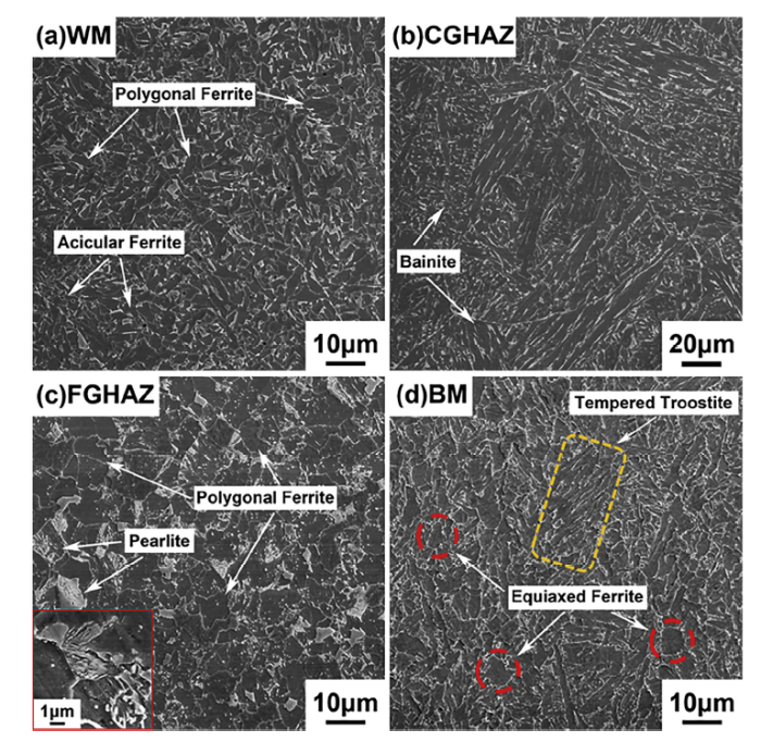
Fig. 2 illustrates typical SEM micrographs of the welded joints. Microstructure of the weld metal (WM) is characterized by fine acicular ferrites with randomly arranged polygonal ferrites, as shown in Fig. 2(a) [22]. Due to high peak temperature (significantly higher than Ac3, 1135 K) and long soaking time, microstructures of the base metal (BM) transform into coarse austenite grains in the CGHAZ. Fig. 2(b) shows the bainitic laths and bainitic granules within the coarse equaixed prior austenite grains (PAGs) with an average size of 51.7 μm in the CGHAZ adjacent to the WM. Fig. 2(c) presents a polygonal ferrite and pearlite structure in the fine grained heat-affected zone (FGHAZ) close to the BM. Finely dispersed cementite is clearly represented in the inset of Fig. 2(c). Representative microstructure of the as-received 12MnNiVR BM is shown in Fig. 2(d), which has a characteristic tempered sorbite structure mainly composed of equiaxed ferrites and fine spheroid-like carbides. In addition, tempered troostite, the lath ferrite retaining the orientation of quenched martensitic laths with finely dispersed cementite, can also be seen in Fig. 2(d), as marked by yellow dash lines.
Fig. 2. Typical microstructures of the 12MnNiVR steel welded joint: (a) WM; (b) CGHAZ; (c) FGHAZ; (d) BM.
To investigate the heterogeneous structures of the welded joints, typical EBSD results on the WM, CGHAZ, FGHAZ, and BM are presented in Fig. 3. Grain boundary maps in Fig. 3 (a) to (d) illustrate the multiple boundary structures. The WM with fine grain size of 2.3 μm is mainly composed of high angle grain boundaries (HAGBs). Normalized frequency of HAGBs (misorientation θ>10°) of the WM is 83.6%, while that of LAGBs (misorientation θ<10°) is 16.4%, as shown in Fig. 3(a). The CGHAZ (Fig. 3(b)) shows a typical mixed structure of coarse PAGs and lath bainites. The PAG boundaries are mostly high misorientation angle boundaries in nature [23]. The fraction of the HAGBs is 38.7%, and the sub-boundaries within the PAGs, such as block and lath boundaries with low misorientation (θ<10°), has a frequency of 61.3%. Comparing the grain boundary maps in Fig. 3(c) and (b), it is found that the fine PAGs of 4.6 μm in the FGHAZ have fewer substructures with a lower frequency (19.6%) of LAGBs and a higher frequency (80.4%) of HAGBs. The BM has a grain boundary misorientation distribution of HAGBs (35.8%) and LAGBs (64.2%), as shown in Fig. 3(d).
Fig. 3. Crystallographic characteristics of 12MnNiVR steel welded joints analyzed by EBSD: (a) WM, (b) CGHAZ, (c) FGHAZ, (d) BM grain boundary maps and (e) WM, (f) CGHAZ, (g) FGHAZ, (h) BM Z axis invers pole figure in the transverse direction (TD). (Red lines indicate grain boundaries with a misorientation angle higher than 10° and blue lines indicate grain boundaries with a misorientation angle less than 10°).
Fig. 3(e-h) shows the orientation image maps of the welded joints. Different colors indicate various orientations in these figures. In Fig. 3(e), it can be seen that the WM comprises interlocking acicular ferrites with various crystal orientations. As clearly displayed in Fig. 3(f), there are limited orientation variations within the CGHAZ. High length/width bainitic laths with similar colors/orientations are observed within coarse PAGs. The FGHAZ shows more colors in Fig. 3(g), especially for the fine equiaxed grains. High length/width blocks with single color/orientation can still be observed, but more equiaxed grains with color gradient exist in the FGHAZ. Inverse pole figure (IPF) in Fig. 3(h) shows large orientation variations of tempered sorbites and tempered troostites in the BM.
Fig. 4(a) shows the macrograph of the as-welded 12MnNiVR weldment, which clearly exhibits four different zones, including WM, CGHAZ, FGHAZ, and BM. Hardness line scanning was conducted at the mid-thickness across the entire welded joints. A microhardness profile is shown in Fig. 4(b) based on the Vickers hardness values measured from the cross-sectional weldment (marked by rectangle in Fig. 4(a)). Four distinguished regions are observed with different hardness magnitudes. The WM shows high yet uniform hardness values of 245 HV0.2. In contrast, the HAZ has a nonuniform hardness distribution. The hardness value decreases from 240 HV0.2 of the CGHAZ to 190 HV0.2 of the FGHAZ, largely due to the gradually decreased peak temperatures from the CGHAZ to the FGHAZ. BM hardness on the left side ranges from 220 HV0.2 to 230 HV0.2 without significant variation. Whereas, the BM adjacent to the HAZ shows a hardness dip (below 210 HV0.2), which is correlated to the overtempered zone.
Fig. 4. Mechanical properties of the welded joints: (a) Macrograph of a one-pass 12MnNiVR steel weldment (The region marked by white rectangle is used for hardness test); (b) Vickers hardness profile across the weldment; (c) Charpy impact test results from specimens in the as-welded condition for different V-notch positions at 258 K; (d) Tensile test results of full thickness tensile specimen tested at room temperature.
Fig. 4(c) shows the results of Charpy impact test from five different V-notch positions. It can be clearly seen that the toughness values of the FL (49 ± 10 J) and FL0.5 (69 ± 17 J) are lower than those of the FL1 (226 ± 35 J), FL2 (157 ± 32 J), and FL3 (182 ± 12 J). Representative SEM micrographs of Charpy impact fracture surface morphologies are represented in the inset of Fig. 4(c). The fractured surface of the FL specimen is characterized by a large area of cleavage facets with river patterns, as shown in the upper left corner of Fig. 4(c). While the fractured surface of the FL1 specimen mainly consists of large and deep ductile dimples, that of the FL2 is mainly composed of relatively small cleavage facets with long and wide ductile fracture bands, which largely increase the impact energy due to the energy dissipating micro mechanisms [17], as shown in the center and lower right corner of Fig. 4(c), respectively. Such observation is in good agreement with the tested result of impact toughness. The size of the cleavage facets is related to the crack path. The straight crack propagation path in the lath bainite contributes to the large cleavage facets, and the deflected crack propagation path in the lath martensite is corresponding to the small cleavage facets. The large cleavage facets demonstrate that very low crack propagation energy is needed, while the small cleavage facets call for higher crack propagation energy [18]. Concurrently, microcracks propagate in the lath bainite in the CGHAZ without deflection, while microcracks are frequently deflected by the HAGBs of the fine equiaxed grains in the FGHAZ, resulting in a sharp decrease of Charpy impact energy. It is well known that a higher impact toughness needs a stronger crack propagation [24]. HAGBs can efficiently deflect or even arrest the propagation of cleavage microcracks, while LAGBs are unable to lead to a noticeable deviation of cleavage cracks [15,[25], [26], [27], [28]]. Consequently, in terms of EBSD results shown in Fig. 3, frequencies of LAGBs of CGHAZ are the highest, which is consistent with the toughness of impact tests.
Fig. 4(d) exhibits the stress‒strain curve of the welded joints of 12MnNiVR steel for full thickness tensile test. It can be seen that yield strength, ultimate tensile strength, and elongation are 447 MPa, 652 MPa, and 23.5%, respectively. Macrograph in the inset of Fig. 4(d) shows cross-section of the failed specimen after tensile test at room temperature. The rupture location was observed in the CGHAZ (marked by black dash line) close to the outer edge of the WM (marked by red solid line). Cracking with obvious necking occurred in the HAZ of the welded joint. Features of the fracture surface are shown in the SEM fractograph presented in the bottom of Fig. 4(d). The fractured surface shows small and shallow equiaxed dimples. Besides, quasi-cleavage fracture characteristic, which consists of short curved river patterns, microvoids, as well as tear ridges, are saliently presented in the fractograph [29].
A schematic illustration of the heterogeneous microstructural evolution based on the above analyses for both the CGHAZ and the FGHAZ is presented in Fig. 5. During high heat input welding process, it can be clearly seen that significant coarsening of austenite grains in the CGHAZ, and the interior of the austenite is mainly composed of bainitic laths with low misorientation. However, since the peak temperature is low and the duration is short in the FGHAZ, the size of the austenite grains is much smaller compared to the CGHAZ region. It has also been found that the fine austenite grains in the FGHAZ have fewer substructures and are dominated by HAGBs. It is believed that these noteworthy changes in grain sizes and gain boundary types may lead to a variation in mechanical properties [26,30,31].
Fig. 5. Schematic diagram of heterogeneous microstructural features of the HAZ.
Based on the results above, the degradation of mechanical properties in the CGHAZ is postulated to be resulted from the coarse PAG size and the low misorientation between lath bainites. The gradient peak temperatures and soaking time in the HAZ regions determine the heterogeneous nucleation and growth of austenitic grains, which leads to various PAG sizes and different proportions of grain boundaries misorientation. The PAG sizes in the CGHAZ and FGHAZ are 51.7 μm and 4.6 μm, respectively. The frequency of the HAGBs changes from 38.7% in the CGHAZ to 80.4% in the FGHAZ. The reduced PAG size from the CGHAZ to the FGHAZ is believed to curb the martensite or bainitic transformation during the cooling cycle [32,33], which is reflected by the hardness reduction from 230 HV0.2 of the CGHAZ to 200 HV0.2 of the FGHAZ. Simultaneously, lower frequency of HAGBs in CGHAZ leads to a decrease in toughness.
In this work, heterogeneous microstructural features of the 12MnNiVR pressure vessel steel welded joint subjected to high heat input electrogas welding have been systematically characterized. The main conclusions can be summarized as follows:
(1) The microstructure of the WM primarily comprises fine acicular ferrites. The CGHAZ is made up of the bainitic laths and bainitic granules within the coarse equaixed PAGs. The FGHAZ grains are primarily composed of a mixture of polygonal ferrites, pearlites, and fine cementite particles. Tempered sorbites and tempered troostite are the typical microstructures in the BM.
(2) Two distinguished regions are observed with significantly varied hardness magnitudes. The hardness decreases from the CGHAZ of 240 HV0.2 to the FGHAZ of 190 HV0.2 due to the gradually decreased peak temperatures from the CGHAZ to the FGHAZ.
(3) Comparing with FGHAZ, CGHAZ is distinguished by its larger PAG size (51.7 μm) and higher frequency of LAGBs. Such differences may dictate the degradation of the toughness and strength in the CGHAZ.
This work was financially supported by the National Natural Science Foundation of China (Nos. 51622401, 51628402, 51861145312 and 51861130361), the National Key Research and Development Program of China (2016YFB0300602), the Research Fund for Central Universities (No. N172502004), State Key Laboratory of Solidification Processing, Northwestern Polytechnical University (No. SKLSP201805), and the Global Talents Recruitment Program endowed by the Chinese Government. The authors also greatly appreciate the support from Jiangyin Xingcheng Special Steel Works Co., Ltd.
The authors have declared that no competing interests exist.

 WeChat
/
| 〈 |
|
〉 |


