Search for articles:
Qian-Qian Chu , Thomas P. White, Kylie R. Catchpole
Corresponding authors:
Received: 2018-11-25
Revised: 2018-11-27
Accepted: 2018-11-27
Online: 2019-06-20
Copyright: 2019 Editorial board of Journal of Materials Science & Technology Copyright reserved, Editorial board of Journal of Materials Science & Technology
About authors:
1 These authors contributed equally to this work.
More
Abstract
Carbon-based perovskite solar cells show great potential owing to their low-cost production and superior stability in air, compared to their counterparts using metal contacts. The photovoltaic performance of carbon-based PSCs, however, has been progressing slowly in spite of an impressive efficiency when they were first reported. One of the major obstacles is that the hole transport materials developed for state-of-the-art Au-based PSCs are not suitable for carbon-based PSCs. Here, we develop a low-temperature, solution-processed Poly(3-hexylthiophene-2,5-diyl) (P3HT)/graphene composite hole transport layer (HTL), that is compatible with paintable carbon-electrodes to produce state-of-the-art perovskite devices. Space-charge-limited-current measurements reveal that the as-prepared P3HT/graphene composite exhibits outstanding charge mobility and thermal tolerance, with hole mobility increasing from 8.3 × 10⁻³ cm2 V-1 s-1 (as-deposited) to 1.2 × 10⁻² cm2 V-1 s-1 (after annealing at 100 °C) - two orders of magnitude larger than pure P3HT. The improved charge transport and extraction provided by the composite HTL provides a significant efficiency improvement compared to cells with a pure P3HT HTL. As a result, we report carbon-based solar cells with a record efficiency of 17.8% (certified by Newport); and the first perovskite cells to be certified under the stabilized testing protocol. The outstanding device stability is demonstrated by only 3% drop after storage in ambient conditions (humidity: ca. 50%) for 1680 h (non-encapsulated), and retention of ca. 89% of their original output under continuous 1-Sun illumination at room-temperature for 600 h (encapsulated) in a nitrogen environment.
Keywords:
Hybrid organic/inorganic perovskite solar cells (PSCs) have attracted enormous attention due to their outstanding optoelectronic properties and being amenable to the low-cost solution fabrication [1], [2], [3], [4], [5], [6]. Stunning progress has been achieved for this technology, with the power conversion efficiency (PCE) rising from 3.7% to more than 23% [7,8]. Excellent photovoltaic performance has been achieved for wide material combinations and cell architectures, demonstrating the versatility of PSC technology [9], [10], [11]. Nevertheless, most of the highest efficiency cells reported to date rely on the n-i-p configuration, with a stack of substrate/electron transport layer (ETL)/perovskite layer/hole transport layer (HTL)/contact layer. A range of ETLs have been successfully applied to produce high-efficiency devices, such as the widely-used TiO x [12], [13], [14], and SnO2 [15], [16], [17]. Nevertheless, most devices are completed with a noble metal electrode (gold in most cases especially for the n-i-p perovskite solar cells), which has disadvantages including high-cost and inferior stability due to gold migration [18], [19], [20].
Carbon-based electrodes have been reported to be an alternative owing to material abundance, low cost, industrially mature preparation and excellent stability [21,22]. Han et al. fabricated a 12.8% efficient, fully printable mesoscopic PSC with a mesoporous TiO2 and ZrO2 double-layer as the ETL scaffold, printing the carbon-electrode in advance, which was subsequently infiltrated with perovskite [23]. Yang et al. pre-fabricated PbI2 and a carbon electrode, which was then subjected to a CH3NH3I bath, avoiding the damage caused by the solvents in the carbon electrode and increasing the contact between the perovskite layer and the carbon electrode, resulting in a PCE of 11.0% [24]. Though these devices show extraordinary stability, the corresponding photovoltaic performance still lags behind those using metal as the electrode [25], [26], [27], [28]. Thus organic small molecule materials as hole transport layers have been introduced to further improve the efficiency of carbon-based PSCs. For instance, Cholipour et al. reported a carbon electrode based device based on a symmetric 2, 2′, 7, 7′- tetrakis (N,N-di-p-methoxyphenylamine)-9, 9′-spirobifluorene (Spiro-OMeTAD)/carbon cloth/Spiro-OMeTAD architecture, resulting in a PCE of 14.8% [29]. Aitola and colleagues incorporated a single-walled carbon nanotube film infiltrated with Spiro-MeOTAD into a device by a press-transferring method with a PCE of 16.0% [30]. These approaches, however, involve Spiro-MeOTAD as the hole transport layer, which will lead to long-term stability issues due to its susceptibility to humidity, light and heat [31], [32], [33], as well as potential etching of the perovskite by the dopant additives [34]. Therefore, recent research has been focusing on exploiting dopant-free HTLs to fabricate carbon-based PSCs to achieve better stability for PSCs [35,36]. F-graphene modified Spiro-OMED materials without additives have been studied to develop the moisture stability, however resulting in a low efficiency [37]. Zheng et al. dispersed multiwall carbon nanotubes in a Poly(3-hexylthiophene-2,5-diyl) (P3HT) matrix which is widely used in organic solar cells [38], leading to a PCE of 13.4% with excellent thermal stability [39]. Many groups have also employed inorganic materials, such as NiO, CuPc as the HTL in carbon-based PSCs with efficiency up to 17.5% [40], [41], [42]. However, the PCEs of the carbon-based PSCs are still inferior to those of devices with metal electrodes. Therefore, developing a highly-stable, dopant-free HTL with good hole mobility is of great significance for constructing high efficiency and stable carbon-based PSCs.
Here, we report a P3HT/graphene composite HTL with excellent hole mobility, leading to efficient and stable low-temperature-processed carbon-based planar PSCs [43]. Compared with pristine P3HT as the HTL, the composite significantly improves hole transport and collection by the carbon electrode. With this composite HTL, we achieved a record efficiency of 18.1% at reverse scan for the carbon-based PSC. Meanwhile, a stabilized efficiency of 17.8% was certified for the first time in the field of perovskite solar cells by Newport. With a low-temperature compatible process for the ETL and HTL, flexible carbon-based PSCs achieved a record PCE of 12.4%. The cells show outstanding stability, with about 3% loss in PCE after storage in ambient conditions (humidity: ca. 50%) for 1680 h (non-encapsulated device), and retaining ca. 89% of their original performance under 1-sun illumination for 600 h (encapsulated).
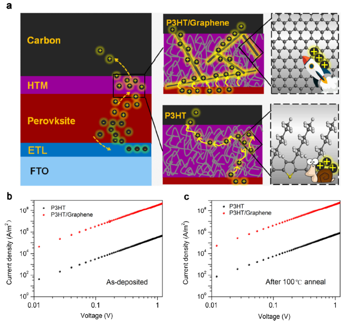
Charge mobility of the selective contact material plays a significant role in determining the photovoltaic performance of perovskite solar cells. The photo-generated electrons are extracted by the ETL, while holes are injected into the HTL and then transport to the carbon electrode (Fig. 1(a) and S1). As illustrated in Fig. 1(a), the long/tortuous routes associated with charge transport along polymer chains of P3HT cause inefficient hole transport and high resistance loss [41]. Therefore, we introduced a hole transport engineering approach by developing a P3HT/graphene composite HTL. The graphene and P3HT were mixed homogenously and resulted in a high-quality contact.
Fig. 1. (a) Illustration of the device with P3HT as the HTL, where the hole transport is slow, resulting in charge accumulation, and device with P3HT/graphene composite as HTL, where hole transports to the carbon electrode quickly. Current density-voltage (J-V) curves of space-charge-limited-current (SCLC) devices based on structures FTO/P3HT/Au and FTO/(P3HT/graphene)/Au (b) before annealing and (c) after annealing at 100 °C.
We first investigated the hole mobility of the P3HT/graphene composite HTL, and compared it with pristine P3HT by the space-charge-limited current (SCLC) method. To prepare the P3HT/graphene HTL, a mixture of graphene and P3HT was magnetically stirred at 60 °C for 24 h, and further centrifuged for 1 h to obtain the supernatant. The P3HT/graphene precursor mixture was sonicated for 1 h before being spin-coated onto the FTO substrate to form a hole transport layer. Au was then deposited on the HTL as the electrode. During the process of fabricating complete solar cells after printing carbon paste onto the HTL, the devices need to be heated at 100 °C for 20 min to dry the carbon paste. Therefore different HTL films with and without annealing were assembled into FTO/P3HT/Au SCLC devices to evaluate the hole mobility (Fig. 1(b) and (c)). According to the Mott-Gurney equation [44], the P3HT/graphene composite shows a much higher hole mobility (8.3 × 10⁻³ cm2 V-1 s-1) than that of pristine P3HT (8.7 × 10⁻⁵ cm2 V-1 s-1) at room temperature. After the heat-treatment step, the mobility of graphene/P3HT further increases to 1.2 × 10⁻² cm2 V-1 s-1, around 100 times higher than that of the bare P3HT (1.3 × 10⁻⁴ cm2 V-1 s-1) after heat treatment. This enhancement might be ascribed to a combination of the better crystallinity of the P3HT polymer and the better conduct between graphene and P3HT following heat treatment. Overall, our P3HT/graphene composite HTL has strong tolerance for heat, showing superiority compared to the other widely used doped HTLs, such as Spiro-MeOTAD and PTAA which have been reported to suffer from serious damage after heating [45], [46], [47].
We next evaluated the influence of the P3HT/graphene composite HTL on the perovskite film and HTL interface quality using a binary cation perovskite composition of (NHCHNH3)0.3(NH3CH3)0.7PbI3 (FA0.3MA0.7PbI3). Multi-cation perovskites with FA as the majority cation have been widely reported to outperform their single cation originator (such as MAPbI3) in terms of both photovoltaic performance and stability [48]. High-quality perovskite films were deposited, as evidenced by the XRD patterns, where no impure phases are detectable (Fig. S2). Notably, doping with FA cations extended the absorption range to $\widetilde{8}$50 nm, compared to $\widetilde{8}$00 nm for the conventional MAPbI3 film (Fig. S3). The HTL film was then deposited onto the perovskite film. The morphologies of the perovskite films before (Fig. 2(a) and S4(a) and (b)) and after (Fig. 2(b) and (c)) depositing the P3HT/graphene HTL are both dense and uniform.
Fig. 2. Surface morphologies of (a) the perovskite film, (b) perovskite film covered with P3HT/graphene HTL. Cross-section SEM images of (c) the perovskite film and P3HT/graphene layer, and (d) the planar carbon-based PSC with P3HT/graphene as HTL.
The cross-sectional SEM image in Fig. 2(c) shows a smooth, uniform interface between the perovskite and the HTL. Meanwhile, the HTL film appears homogeneous, indicating that the graphene is uniformly incorporated through the P3HT (Fig. 2(d)), which would be beneficial for promoting hole transport to the carbon electrode. Planar carbon-based PSCs with P3HT/graphene and P3HT composite as HTL were fabricated and their corresponding cross-sections are shown in Fig. 2(d) and Fig. S5(a) and (b).
Both steady-state and time-resolved photoluminescence (TRPL) measurements can reveal important information about charge transfer and recombination kinetics in films and partial cells. From these measurements (Fig. S5(c) and Fig. S5(d)) we observe that the bare film exhibits a strong steady state PL emission with a narrow linewidth, and a PL decay time of >400 ns. This is indicative of the high quality of the as-deposited perovskite film. Significant quenching of the photoluminescence is seen with the addition of the HTL layer; with the strongest quenching observed for the composite P3HT/graphene film, in both steady-state and transient measurements. The slightly faster PL decay of the P3HT/graphene samples (43 ns) compared to the pure P3HT samples (55 ns) may indicate improved hole extraction at the perovskite-HTL interface, but the significant steady-state PL quenching also suggests the presence of interface recombination, which may ultimately limit the open circuit voltage [49,50]. Nevertheless, as we show below, cells with the P3HT/graphene composite HTL outperform cells with pure P3HT on all performance metrics (current, voltage and fill-factor), most likely a result of the dramatic improvement in HTL carrier mobility as discussed previously.
To further confirm the state-of-the-art electrical properties of our composite HTL, we incorporated the two different HTLs studied in this work into perovskite solar cells in combination with a carbon-electrode. We adopted a planar structure with special SnO2@TiO2 structure as the ETL by using our previously invented chemical bath method [16]. The perovskite films were fabricated by using our previously invented gas pump methods [51], [52], [53], [54]. The photovoltaic performance of the planar carbon-based PSCs with P3HT and P3HT/graphene as HTL were measured, with the results shown in Fig. 3(a) and (b), respectively. The P3HT/graphene composite HTL device yielded a short-circuit current (JSC) of 22.5 mA/cm2, an open-circuit voltage (VOC) of 1.09 V, a fill factor (FF) of 0.74, and a PCE of 18.2%. In comparison, using just P3HT as the HTL resulted in a much inferior performance, with JSC = 20.7 mA/cm2, VOC = 0.99 V, FF = 0.55, and PCE = 11.1%. The incident photon to current conversion efficiency (IPCE) spectra of champion devices with each HTL are shown in Fig. 3(c) (P3HT/graphene) and Fig. S6 (P3HT). The integrated current density from IPCE spectra is slightly lower than from the J-V measurements ($\widetilde{1}$0%). However, we also observe that the integrated current density of the P3HT/graphene HTL device is $\widetilde{3}$.8 mA/cm2 higher than the P3HT device; a very significant increase.
Fig. 3. J-V curves (both reverse and forward scanning direction) of champion planar carbon-based PSCs. (a) P3HT/graphene as HTL, (b) P3HT as HTL. (c) IPCE spectrum and (d) the steady-state output (tracking at max power point under 1-sun illumination) of the champion device with P3HT/graphene as HTL. (e) The statistical PCEs of devices with P3HT/graphene and P3HT as HTL, (f) J-V curves (both reverse and forward scanning direction) of the champion flexible carbon-based PSC on a PEN substrate with P3HT/graphene as the HTL.
Notably, the P3HT/graphene composite HTL also reduced the hysteresis dramatically, as revealed by the reverse and forward scanning curves shown in Fig. 3(a) and (b). The corresponding photovoltaic metrics of both devices are listed in Table S1. The steady-state output was measured under a constant bias voltage at the maximum power point under 1-sun illumination. The P3HT-only devices show an unstable current density at a bias voltage of 0.69 V, resulting in PCE of $\widetilde{1}$0.5% (Fig. S7). In contrast, the P3HT/graphene composite HTL devices exhibit a stable output with a current density of ca. 20 mA/cm2 at a bias voltage of 0.89 V, corresponding to a PCE of ca. 18% (Fig. 3(d)). The steady-state output is almost the same as that extracted from the reverse J-V scans, indicating small hysteresis under these measurement conditions.
The high efficiency of the carbon-based PSC with P3HT/graphene composite HTL reported here has been certified by an accredited independent PV test laboratory (Newport Corporation PV Lab, MT, USA). An un-encapsulated device reached a PCE of 18.1% from reverse scanning and a stabilized PCE of 17.8% (Details of the stabilized testing protocol are provided in experimental section of electronic supplementary information and the Newport certification report). This efficiency is significantly higher than the previously certified PCE of 12.8% and a reported value of ca. 17.5% without certification for carbon-based PSCs [23,41]. This is not only a record efficiency for carbon-electrode based PSCs, but also the first certified stabilized efficiency for all types of PSCs (Fig. S8). Good repeatability was also achieved for cells with the P3HT/graphene composite HTL, as seen from much narrower PCE distributions from 32 devices (Fig. 3(e) and Fig. S9(a-c)) compared to pure P3HT-based devices. The average parameters for devices with P3HT/graphene HTLs are PCE = 17.49 ± 0.42%, JSC = 22.30 ± 0.62 mA/cm2, VOC = 1.06 ± 0.02 V, and FF = 0.74 ± 0.02. The equivalent values for P3HT HTL devices are PCE = 9.73 ± 0.95%, JSC = 19.33 ± 0.61 mA/cm2, VOC = 0.99 ± 0.04 V, and FF = 0.51 ± 0.04.
Our carbon-based cell structure with P3HT/graphene HTL is also compatible with flexible PSCs. Fig. 3(f) shows the J-V curve of the champion flexible device, with a record PCE of 12.4%, VOC = 0.96 V, JSC = 18.82 mA/cm2 and FF = 0.68. The efficiency is significantly higher than the previously reported value of 8% for flexible carbon-based PSCs [55].
Long-term stability is one of the key challenges for commercialization of perovskite photovoltaic technology. Here, we investigated the stability of our planar carbon-based PSCs based on P3HT and P3HT/graphene HTL. We first tracked the non-encapsulated device performance under ambient conditions (humidity: ca. 50%) without illumination for 1680 h (Fig. 4(a)). The PCE of the device based on pure P3HT dropped quickly, reaching $\widetilde{5}$0% of its starting efficiency after less than 400 h. However, the P3HT/graphene based device showed excellent stability against moisture for the HTL could be a good hydrophobic barrier layer inhibiting the water-induced degradation processes of perovskite films, as revealed by a 3% drop in PCE after storage. The detailed time evolution of each of the photovoltaic parameters of a P3HT/graphene based device are listed in Table S2, and the corresponding J-V curves of the fresh and aged device are shown in Fig. S10. Our results are consistent with previous reports that large-scale graphene is beneficial for preventing the infiltration of water vapour [56], [57], [58].
Fig. 4. (a) Normalized PCE evolution of non-encapsulated devices with P3HT and graphene/P3HT as the HTLs stored in the dark for 1680 h in air, (b) Normalized PCE evolution of encapsulated devices with P3HT and P3HT/graphene as the HTLs under constant 1-sun illumination with ultraviolet filter and infrared cut-off filter.
Furthermore, the light stability was evaluated by testing encapsulated devices under 1-sun illumination for 600 h (Fig. 4(b)). The device with a P3HT HTL shows a rapid degradation, reaching $\widetilde{2}$5% of its original output after $\widetilde{7}$5 h of measurement. In contrast, the P3HT/graphene HTL device exhibits much better light stability, initially increasing in PCE (within the first $\widetilde{1}$50 h), and retaining $\widetilde{8}$9% of its original PCE after 600 h of testing. The initial efficiency enhancement in the early stages of the test might originate from light-induced defect healing in the perovskite layer [1,57,59]. Detailed evolution of J-V parameters of the P3HT-graphene based devices under these test conditions are listed in Table S3, and the J-V curves before and after aging are shown in Fig. S11. The performance degradation of PSCs under light is thought to be mainly caused by the unfavourable ion diffusion from perovskite films to the electrodes [1,6,60,61]. The graphene in the HTL may hinder the iodide escape from perovskite film, thus supressing the consequent degradation of device performance [62].
We developed an efficient P3HT/graphene HTL that provides outstanding hole mobility, thus improving the hole transport. The composite HTL is also compatible with carbon-electrodes, leading to state-of-the-art, metal-electrode-free solar cells. A record efficiency for carbon-based PSC of 18.1% from reverse scanning and a PCE of 17.8% under stable testing protocol (certified) was reported. The device also shows outstanding stability towards moisture, oxygen and light. Negligible efficiency drop was observed by placing our unencapsulated P3HT-graphene composite HTL based cells under ambient conditions in the dark for more than 1600 h. Concurrently, under continuous 1-Sun illumination for 600 h, the encapsulated device exhibits a PCE of about 89% of the original output. This work paves the way for constructing highly-efficient and stable perovskite devices that are promising for future commercialization.
Q. -Q. Chu, B. Ding and J. Peng conceived and designed the overall experiments. Q. -Q. Chu, B. Ding and J. Peng prepared and characterized the perovskite cell devices. H. Shen, X. Li and Y. Liu conducted the PL and TRPL measurements and analysis. Q. Q. Chu and B. Ding conducted the XRD and SEM measurements and analysis. B. Ding and J. Peng performed the SCLC measurements and analysis. Q. -Q. Chu, B. Ding, J. Peng, H. Shen, C.-X. Li, C.-J. Li, G.-J. Yang, T. P. White and K. R. Catchpole contributed to the results analysis and interpretation. The manuscript was mainly written by Q. -Q. Chu, B. Ding and J. Peng. G.-J. Yang, T. P. White and K. R. Catchpole supervised the project. All authors contributed to the discussion of the results and revision of the manuscript.
The work was supported by the National Program for Support of Top-notch Young Professionals and the Australian Government through the Australian Renewable Energy Agency (ARENA). Responsibility for the views, information or advice expressed herein is not accepted by the Australian Government.
The authors have declared that no competing interests exist.

 WeChat
/
| 〈 |
|
〉 |


