Search for articles:
Zhewen Ma , Darvaish Khan
Corresponding authors:
Received: 2019-02-12
Revised: 2019-04-5
Accepted: 2019-05-15
Online: 2019-10-05
Copyright: 2019 Editorial board of Journal of Materials Science & Technology Copyright reserved, Editorial board of Journal of Materials Science & Technology
More
Abstract
Two kinds of metal-organic frameworks (MOFs) based on Co (II) and Fe (II) as metal ions and trimasic acid (TMA) as organic linker were synthesized. They were used to prepare corresponding MgH2-TM MOF (TM = Co, Fe) composites via ball-milling. X-ray diffraction analyses show the formation of Mg2Co and α-Fe phases in MgH2-TM MOF composites after decomposition. Both of the well dispersed Mg2Co and α-Fe nanoparticles exhibit considerable catalytic efficiency in accelerating the sorption kinetics of MgH2. The dehydrogenated MgH2-Fe MOF composite shows faster hydriding kinetics than the pure MgH2 and MgH2-Co MOF. Meanwhile, the apparent dehydrogenation activation energy (Ed) of the MgH2-Co MOF and MgH2-Fe MOF composites are 151.3 ± 9.4 and 142.3 ± 6.5 kJ/mol H2, both of which are lower than that of pure MgH2 (181.4 ± 9.2 kJ/mol H2). The improvement on the sorption kinetics of the MgH2-TM MOF powders is mainly attributed to the catalytic effects of nano-sized Mg2Co and α-Fe formed on the surface of Mg/MgH2 particles.
Keywords:
Undoubtedly, the global increasing demand of energy production and environmental contamination caused by the enormous consumption of fossil fuels are the most significant issues in 21st century [1,2]. As one kind of green and renewable candidates to replace fossil fuels, environmental friendly hydrogen energy system possesses a high energy content per unit mass (142 MJ/kg) with pure water as the only combustion product [3,4]. MgH2 has been considered as one of the applicable hydrogen storage carriers in virtue of its high hydrogen uptake capacity (7.6 wt%), abundant deposit as well as low cost. However, the enthalpy value (74.7 kJ/mol H2) of MgH2 indicates its high thermodynamics stability [5]. The high operating temperature (>623 K) and the sluggish hydrogen de/absorption kinetics of MgH2 impede the practical application of magnesium-based material for hydrogen storage [6,7]. To enhance the thermodynamics and de/hydriding kinetics of MgH2, a series of strategies including alloying [[8], [9], [10]], nanoconfinement [[11], [12], [13]] as well as nanoscaling [[14], [15], [16], [17], [18]] have been widely used in Mg based hydrogen storage material. Besides, the addition of catalytic metals e.g. Ni [[19], [20], [21]], Co [22,23], Fe [[22], [23], [24], [25], [26]], Ti [[25], [26], [27]], V [[27], [28], [29]], Cu [30,31], Pd [[30], [31], [32]], Nd [33,34], Y [35], metal oxides [[36], [37], [38]] and metal halides [[39], [40], [41], [42]] etc. into Mg/MgH2 matrix have been proved to be another effective strategy accelerating the sorption kinetic performances of MgH2. On the other hand, like other kinds of solid state carriers including carbon nanostructures, pure metals and metallic compounds, metal organic frameworks (MOFs) have been developed as one of candidates for physisorption of hydrogen since the pioneer work of Yaghi et al. in 2003 on the hydrogen absorption in MOFs [43,44]. Numerous researches on the hydrogen storage behaviors of MOFs have been reported in the past decade. For instance, MOFs such as Zn4O(BDC)3 (MOF-5) and Zn4O(BTB)2 (MOF-177) exhibited uptakes of 10 wt% and 7.0 wt% H2 at 77 K, respectively [45,46]. Farha et al. [47] reported a MOF named NU-100 with a high Brunauer Emmett Teller (BET) specific surface area of 6143 m2/g and the MOF exhibits a high hydrogen storage capacity (approximately 9 wt%) under 56 bar H2 pressure at 77 K. With the purpose to further improve the hydrogen physisorption capacities of MOFs at 77 K or room temperature, extensive work on MOFs mainly focus on the functionalization of ligands, manipu-lation of pore size and increment of pore volume and specific surface area [48]. While the catalytic effects of MOFs on the (de)hydriding thermodynamics and kinetics of Mg/MgH2, have rarely been reported in the literature.
In this work, trimasic acid (TMA) and Co (II), Fe (II) based MOFs (TMA-TM MOFs) with environmentally friendly solvents were firstly synthesized in deionized water (DI water) at 298 K. To explore the catalytic role TMA-TM MOFs played in Mg/MgH2, the overall hydrogen storage properties and corresponding thermodynamics and kinetics of pure MgH2 and MgH2-TMA-TM MOF (MgH2-TM MOF) (TM = Co, Fe) composites were systematically investigated.
Co(NO3)2·6H2O (Aladdin, 99.99%) and FeSO4·7H2O (Aladdin, 99.95%) as metal ion sources, trimasic acid (TMA) (H3BTC), (Aladdin, 98%) was used as organic linker for preparations of TMA-TM MOFs. Sodium hydroxide (Aladdin, 98%) was used to adjust the pH value of TMA solution. A Co(NO3)2 solution was prepared by dissolving 0.009 mol Co(NO3)2·6H2O into 60 mL DI water. A FeSO4 solution was obtained by the same operation. Meanwhile, 0.0045 × 2 mol TMA was dissolved into 120 mL DI water and the pH of the solution was adjusted to 7 by dropping wise addition of 0.5 M NaOH. The introduction of hydroxyls by adding appropriate NaOH into the TMA solution neutralizes the hydrogen ions derived from H3BTC and facilitate the complete dissolution of H3BTC into DI water. Then the prepared TMA solution (120 mL) was equally divided into two beakers and Co2+ and Fe2+ containing solutions were then added into the TMA solutions, respectively, under a constant stirring rate of 1000 rpm. Minutes later, pink-colored (TMA-Co MOF) and brown-colored (TMA-Fe MOF) precipitates both gradually appeared in their individual beakers. Ten hours of mixing time was given for the complete formations of MOFs. The synthesized precipitates were washed with excess DI water to remove residuary of reactants. Finally, the prepared TMA-TM (TM = Co, Fe) MOFs were dried in vacuum at 333 K for 8 h, followed by another 24 h at 373 K to preliminarily remove the external solvent of MOFs. Then the dried MOFs were preserved in the glove box for further measurements.
The MgH2-TM MOF (TM = Co, Fe) composites were prepared in a planetary ball mill with the ball-to-powder weight ratio of 20:1. For the preparation of each MgH2-TM MOF composite, about 1.8 g MgH2 (produced by Shanghai Mg Power Technology Co. Ltd., purity >98%) [19] and 0.2 g TMA-TM MOF (TM = Co or Fe) powders were added into a sealed steel container (100 mL) under argon atmosphere (1 bar) and ball milled at 150 rpm for 8 h. The rotation speed of 150 rpm for ball milling was selected for the homogenization of TMA-TM MOFs powders with MgH2 in the MgH2-TM MOF (TM = Co, Fe) composites without severe destruction of the MOF structures. Same amount (2.0 g) of pure MgH2 was also ball milled in another container with same parameters for comparison.
The surface areas, average pore volumes and pore sizes of the TMA-TM (TM = Co, Fe) MOFs were examined by N2 absorption on a 3H-2000PS2 (Beishide Co. Ltd). The structural analysis of the TMA-TM MOFs was performed via Fourier transform infrared spectroscopy (FTIR) by a Nicolet iS5 (Thermo Fisher Scientific Inc.) equipped with a horizontal ATR accessory. The thermal stability of MOFs was evaluated on thermolgravimetry (TG) and differential scanning calorimetry (DSC, Netzsch STA449F3 Jupiter) analysis by heating samples from 293 K to 823 K under 1 bar of argon atmosphere (heating rate =5 K/min). X-ray diffraction (XRD, D/max 2550 V L/PCX) measurements were carried out for the phase identification of the MgH2-TM MOF (TM = Co, Fe) and the pure MgH2 powders in various states. A scotch tape was used on the sample holder to prevent the samples from oxygen and H2O contaminations and the collected data were analyzed using Jade 6.5 software. The morphology and microstructures of the MgH2-TM MOF (TM = Co, Fe) composites were identified by a transmission electron microscope (TEM, JEM-2100 F) and a scanning electron microscope (SEM, Phenom-XL) equipped with an energy dispersive spectrometer (EDS). The hydriding/dehydriding properties of the samples were evaluated using a Sievert type pressure-composition-temperature (PCT) apparatus. The auto-PCT sorption tests at various temperatures including 598, 623 and 648 K were performed with minimum and maximum hydrogen pressures of 0.01 and 4 MPa, respectively. Before the PCT measurements, the MgH2-TM MOF (TM = Co, Fe) composites and the as milled pure MgH2 were all fully activated at 753 K for 1 h by operating a dehydrogenation process in vacuum. Dehydrogenation properties of the samples were examined by DSC under 1 bar argon atmosphere at different heating rates (3, 5 and 10 K/min) from 298 K to 773 K. The sample powders were both hydrogenated at 623 K under 3 MPa hydrogen pressure for 2 h and dehydrogenated at 673 K in vacuum for 2 h in the PCT apparatus for XRD, SEM, TEM as well as DSC measurements.
Fig. 1. Schematic diagram of synthesized TMA-TM MOFs (TM = Co, Fe).
Fig. 2. SEM images of pure MgH2 (a), TMA-Co MOF (b) and TMA-Fe MOF (c).
Table 1 Pore structural parameters of TMA-TM MOFs (TM = Co, Fe) using N2 adsorption isotherms.
| Samples | BET surface area (m2/g) | BJH pore size (nm) | Pore volume (cm3/g) |
|---|---|---|---|
| TMA-Co MOF | 507.97 | 5.90 | 0.2339 |
| TMA-Fe MOF | 1015.49 | 3.02 | 0.5317 |
Fig. 3 displays the FTIR spectra of the TMA and TMA-TM (TM = Co, Fe) MOFs obtained in waterless testing environment for structural identification. As shown in Fig. 3(a), the most important functional groups in TMA are carbonyl groups at about 1700 cm-1, C—O single stretching bonds at about 1454 and 1403 cm-1. Additionally, The peak at 1274 cm-1 corresponds to C—O—H stretching bonds. According to Fig. 3(b), the C=O bonds peak split into two peaks at 1616 and 1558 cm-1 for TMA-Co MOF, demonstrating the interaction of Co ion and carboxylate groups [49]. It is worth noting that the peaks at 1274 and 930 cm-1 disappear in the FTIR spectra of TMA-Co MOF as compared to that of TMA, which is ascribed to the O–H bonds breaking during synthetic process (see Fig. 1). The FTIR spectra of the TMA-Fe MOF are almost identical to that of TMA-Co MOF, suggesting a similar microstructure of two kinds of MOFs. To estimate the thermostability of the MOFs, the TG and DSC profiles of TMA-Co MOF and TMA-Fe MOF are presented in Fig. 4(a) and (b), respectively. According to the distinct plateaus in TG curves for each of the MOF samples, the decomposition processes both contain two steps at about the temperature ranges of 360-450 and 700-800 K for TMA-Co MOF as well as ones of 400-500 and 750-800 K for TMA-Fe MOF. It is easily to understand that the first mass losses can be due to the loss of solvent (DI water) and the other ones at relatively high temperature range are put down to the degradations of TMA-TM MOFs. It should be pointed out that the residual solvent in the micro-structures of MOFs could not be completely removed until the temperature increases to 360-450 K for TMA-Co MOF as well as ones of 400-500 K for TMA-Fe MOF. Furthermore, two broader endothermic peaks in DSC curve for each of MOF correspond well to the decomposition steps discussed above. Moreover, when heating up to 773 K at the heating rate of 5 K/min, the weight losses of the as prepared TMA-TM MOFs (TM = Co, Fe) are evaluated to be about 53 wt% and 60 wt%, respectively.
Fig. 3. FT-IR spectra of TMA (a), TMA-Co MOF (b) and TMA-Fe MOF (c) synthesized in DI water.
Fig. 4. TG and DSC curves of TMA-Co MOF (a) and TMA-Fe MOF (b) at the heating rate of 5 K/min.
Fig. 5(a)-(j) displays the XRD patterns of the TMA-TM MOFs (TM = Co, Fe), pure MgH2 and the MgH2-TM MOF composites in various states. As shown in Fig. 5(a) and (b), the characteristic peaks for the crystallographic TMA-Co MOF can be found at relatively low diffraction angles (2θ) including 17.62°, 18.81°, 27.26° and 35.58°. They are much similar with those of TMA-Co MOF (17.78°, 18.92°, 27.33° and 35.74°, respectively), suggesting the analogous crystal structures for TMA-TM MOFs (TM = Co, Fe). Apart from a small amount of Mg, almost all diffraction peaks of the as milled MgH2 powders (Fig. 5(c)) and MgH2-TM MOF composites (Fig. 5(d) and (e)) can be indexed with pure tetragonal β-MgH2 MgH2. Analogously, Same phases can also be observed in pure MgH2 powder after hydrogenation at 623 K for 2 h (Fig. 5(f)). Moreover, peak from TMA-TM MOFs at 2θ ≈18.8° can also be detected in MgH2-TM MOF composites after the ball milling, demonstrating the presences of TMA-TM MOFs (TM = Co, Fe) in as milled composites without the destruction of crystal structures. When hydrogenation are performed at 623 K for 2 h, the MgH2-Co MOF sample is composed of β-MgH2, Mg2Co and MgO, while α-Fe phase can be found along with β-MgH2 and MgO in the hydrogenated MgH2-Fe MOF composite (see Fig. 5(g) and (h)). The appearance of Mg2Co phase indicating a reaction of Co and Mg in the MgH2-Co MOF powder at high temperatures. The reaction can be expressed as follows:
2 Mg + Co = Mg2Co (1)
Fig. 5. XRD patterns of TMA-Co MOF (a), TMA-Fe MOF (b), pure MgH2 and MgH2-TM MOF (TM = Co, Fe) composites at various states: as milled (c, d, e), re-hydrogenated at 623 K for 2 h (f, g, h), and dehydrogenated at 673 K for 2 h (i, j), respectively.
For the dehydriding processes in Fig. 5(i) and (j), the broad diffraction peaks of two kinds of composites both match for hexagonal Mg as majority phase when the re-hydrogenated MgH2-TM MOF samples are heated in vacuum at 673 K for 2 h. Meanwhile the Mg2Co and α-Fe phases can be observed in dehydrogenated MgH2-Co MOF and MgH2-Fe MOF composites, respectively. Despite possible oxidation occurred during composites preparations, the presence of oxygen in MgO, cobalt in Mg2Co and iron in α-Fe phases reveals the degradation of TMA-TM MOFs (TM = Co, Fe) at high temperatures. According to Fig. 4, Fig. 5, it can be deduced that the TMA-TM MOFs in composites are both destabilized by the increment of temperature. The chemical bonds among component in MOFs rupture at the high temperature (753 K) during activation processes and consequently, resulting in the collapses of the structure in TMA-TM MOFs (TM = Co, Fe). The former ball-milling processes increase the contact areas between MgH2 particles and the MOF additives. The large contact areas make it easy for cobalt and oxygen from TMA-Co MOF to react with surrounding Mg to form Mg2Co and MgO, respectively. The iron from the decomposition of TMA-Fe MOF does not react with Mg even at high temperatures, thus α-Fe phase can be detected in both re/dehydrogenated MgH2-Fe MOF composites. It is necessary to point out that there is no trace of Mg2CoH5 phase presented in the XRD pattern of hydrogenated MgH2-Co MOF sample. Indeed, it has been widely reported that high temperature, high hydrogen pressure and long duration are three vital factors dominant the generation of Mg2CoH5 phase. For instance, Zolliker et al. [50] reported a sintering technique in a condition of 690-720 K, 4-6 MPa H2 pressure to prepare Mg2CoH5. Selvam et al. [51] obtained Mg2CoH5 sample by high-pressure sintering at 723 K under 9 MPa H2 for more than 7 d. The conditions given in this work (at 623 K under 3 MPa H2 pressure for 2 h) is unsuitable for the formation of Mg2CoH5 during hydrogenation process. Analogously, α-Fe phases can both be detected in rehydrogenated/dehydrogenated MgH2-Fe MOF samples in Fig. 5(h) and (j), while the characteristic peaks of Mg2FeH6 phase are invisible in Fig. 5(h). The similar phenomena have been reported in Mg@Fe composite and Mg-Fe-La ternary composite synthesized through arc plasma method [52,53]. In fact, it has been established that the formation of Mg2FeH6 phase needs conditions including high temperature, high H2 pressure as well as long duration for hydriding [54]. This is the main interpretation for the absence of Mg2FeH6 phase in hydrogenated MgH2-Fe MOF powder under given conditions. The contact areas between the MOF additives and MgH2 particles increases during the ball-milling process and parts of needle-like TMA-Co MOF and rod-shaped TMA-Fe MOF can penetrate the extremely thin MgO layer covered on MgH2 particles.
The typical SEM images of as milled, hydrogenated and dehydrogenated MgH2 samples are given in Fig. 6(A), (H) and (O), respectively. It can be found that the average particle size of the as milled pure MgH2 remains to be about 10 μm, which means that the ball-milling process at 150 rpm for 8 h could not significantly change the particle size of MgH2 powder. Besides, the irregular-shaped MgH2 and Mg with the particle sizes of about 30 μm in Fig. 6(H) and (O) indicating a noticeable agglomeration of MgH2/Mg particles during (de)/hydriding at high temperature. Similar phenomenon can also be found on the MgH2-TM MOF (TM = Co, Fe) samples in various states (see Fig. 6(B)-(G)). The particle sizes of the composite powders both increase from about 10 μm (as milled state) to 20-30 μm (re/dehydrogenated states). What’s more, Fig. 6(I)-(K), (L)-(N) and (P)-(U) of EDS maps reveal the distributions of Co, Fe and O, respectively. For the as milled MgH2-TM MOF (TM = Co, Fe) composites, Co, O and Fe, O are both uniformly distributed on the large MgH2 particles of the MgH2-Co MOF and MgH2-Fe MOF powders, respectively. It can also be clearly observed from Fig. 6(I)-(N) that Co and Fe distributed homogeneously on the MgH2 (re-hydrogenated) and Mg (dehydrogenated) particles, demonstrating the uniform distributions of Mg2Co and α-Fe phases on the surface of MgH2/Mg particles in various states. It is due to the appropriate ball-milling process during the preparations of the composites.
Fig. 6. SEM micrographs of the as milled (A), hydrogenated (H) and dehydrogenated (O) pure MgH2 powders, the as milled (B), (E), hydrogenated (C), (F) and dehydrogenated (D), (G) MgH2-TM MOF (TM = Co, Fe) composites, respectively. The corresponding EDS mappings showing distributions of Co (I-K), Fe (L-N) and O (P-U) (As milled: after ball-milling; Ab: absorption; De: desorption).
TEM observations were conducted in Fig. 7 to further reveal the morphology of the hydrogenated MgH2-TM MOF composites. Fig. 7(a) and (e) display the typical bright field micrographs of the MgH2-TM MOF (TM = Co, Fe), respectively. The particle size of the irregular-shaped MgH2-Co MOF composite is measured to be about 500 nm, which is larger than that of MgH2-Fe MOF. Some dispersive particles with dark contrast can be observed on the surfaces of the composites. Fig. 7(b) and (f) illustrate the selected area electron diffraction (SAED) patterns of the MgH2-TM MOF (TM = Co, Fe) samples. All the diffraction rings or points of the MgH2-Co MOF sample confirm the presences of MgH2, MgO and Mg2Co phases. At the same time, the SAED pattern in Fig. 7(f) for the MgH2-Fe MOF sample can be indexed with (101), (002), (202) and (103) for MgH2, (110), (211) and (310) for α-Fe and (200) for MgO. The phase identifications for the composites are in accordance with the XRD analyses. The appearance of MgO phase is mainly ascribed to the reaction between Mg and O (provided by the decomposition of TMA-TM MOF) during de/hydriding cycles. With the purpose to reveal the morphology of Mg2Co and α-Fe phases covered on MgH2, the diffraction points of Mg2Co (442) plane and α-Fe (211) plane are taken to draw the dark field TEM micrographs for the MgH2-Co MOF and MgH2-Fe MOF, respectively (see Fig. 7(c) and (g)). Both of the Mg2Co and α-Fe nanoparticles shown in bright contrasts are well dispersed on the surfaces of large-sized MgH2, which is in good agreement with the EDS mappings of Co and Fe in former SEM observations. It is also found in Fig. 7(c) and (g) that the particle sizes of Mg2Co particles are in the range of 5-30 nm, which are larger than those of α-Fe (several nanometeres). Moreover, High Resolution Electron Microscope (HRTEM) was performed to investigate the micro-structures of the MgH2-TM MOF (TM = Co, Fe) composites. Two of the interplanar spacings of the selected zones in Fig. 7(d) can be determined to be about 0.2203 and 0.2189 nm, both of which are nearly identical to that of Mg2Co (511) plane (0.2199 nm). Similarly, MgH2 (101) plane and MgH2 (200) plane with interplanar spacings of 0.2537 nm and 0.2272 nm can also be confirmed in Fig. 7(d). As for the HRTEM of the MgH2-Fe MOF sample in Fig. 7(h), an atomic layer with the interplanar spacing of 0.2537 nm is identified to be MgH2 (101) plane (0.2510 nm). Simultaneously, another atomic layer structure is found in the enlarged image presented in the inset Fig. 7(h). The interplanar spacing is measured to be 0.2035 nm, which is in good agreement with that of Fe (110) plane (0.2026 nm).
Fig. 7. Typical bright field TEM micrographs of the hydrogenated MgH2-Co MOF (a) and MgH2-Fe MOF (e) samples, the corresponding SAED patterns (b), (f), the dark field micrographs (c), (g) contributed by Mg2Co (442) and α-Fe (211) diffraction rings and the HRTEM images (d), (h), respectively.
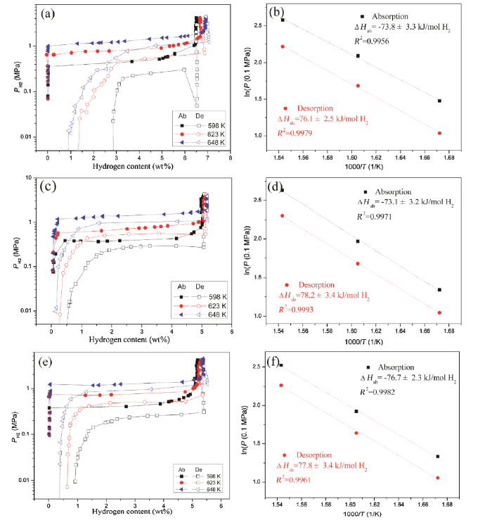
The (de)hydriding thermodynamics and kinetics of the pure MgH2 and the MgH2-TM MOF (TM = Co, Fe) powders are estimated by using the PCT technique. The PC isotherms of the as milled MgH2 and the MgH2-TM MOF (TM = Co, Fe) composites measured at 598, 623 and 648 K in a H2 pressure range from 0.1 to 40 bar are presented in Fig. 8(a), (c) and (e), respectively. The parameters of hydrogen storage behaviors for the three samples collected from PCT tests are also listed in Table 2. It can be found in Fig. 8(a) that the single slant plateau associates with the re-dehydrogenation of Mg is presented at each of assigned temperatures. What’s more, there is no distinct hydrogen desorption plateau can be observed in the PC isotherm for pure MgH2 at each of testing temperatures. In addition, a sharp drop of the hydrogen plateau pressure at the initial stage of dehydrogenation is observed at 598 K. Hence, it is reasonable to believe that the as milled MgH2 powder still possesses poor hydrogen de/absorption performances during re/dehydrogenation. On the contrary, the single flat plateaus owning to the formation and decomposition of MgH2 are obtained at 598, 623 and 648 K for the MgH2-Co MOF and MgH2-Fe MOF powders in Fig. 8(c) and (e), respectively. Each of the hydrogen desorption profiles for the composites exhibits an evident plateau with no diminution of H2 pressure, even the temperature decreases to 598 K. It means that the hydrogen (de)absorption kinetic properties of the MgH2-TM MOF (TM = Co, Fe) composites can be effectively aggrandized with the additions of the TMA-TM MOFs (TM = Co, Fe). According to the data collected in Table 2, the maximum hydrogen uptake amounts at 598, 623 and 648 K for the MgH2-Co MOF composite are 5.08, 5.14 and 5.19 wt%, respectively, which are a little lower than those of the MgH2-Fe MOF composite (5.19, 5.30 and 5.37 wt%, respectively). The reversible hydrogen sorption capacities of the composites increase with the rise of temperatures, suggesting the enhanced sorption kinetics at higher temperatures. It is noteworthy that the hydrogen uptake amounts of the MgH2-TM MOF (TM = Co, Fe) composites at series temperatures are all lower than the theoretical maximum hydrogen storage capacity of pure Mg (7.6 wt%) [4,5], owning to the addition of TMA-TM MOFs (TM = Co, Fe) and the formation of MgO phase. Fig. 8(b), (d) and (f) illustrates the van’t Hoff plots and the corresponding linear fittings (lnP vs. 1000/T) (P donates the hydrogen pressure for ab/desorption plateau and T represents the corresponding temperature) of as milled MgH2 and the MgH2-TM MOF samples, respectively. The hydriding and dehydriding enthalpies (ΔHab and ΔHde) of the dehydrogenated MgH2-Co MOF sample are therefore calculated to be -73.1 ± 3.2 and 78.2 ± 3.4 kJ/mol H2. As to the MgH2-Fe MOF composite after dehydriding, the ΔHab and ΔHde are evaluated to be -76.7 ± 2.3 and 77.8 ± 3.4 kJ/mol H2. They are fairly close to the standard values of Mg (±74.7 kJ/mol H2) [55] as well as the dehydrogenated MgH2 (-73.8 ± 3.3 and 76.1 ± 2.5 kJ/mol H2, respectively) in this work. Herein, the thermodynamic performances of the MgH2-TM MOF (TM = Co, Fe) remain nearly unchanged with the addition of TMA-TM MOFs.
Fig. 8. PC isotherms and the van’t Hoff plots of pure MgH2 (a, b), the MgH2-Co MOF (c, d) and the MgH2-Fe MOF (e, f) composites tested at 589, 623 and 648 K.
Table 2 PCT parameters of pure MgH2 and the MgH2-TM MOF (TM = Co and Fe) composite samples obtained at different temperatures.
| Samples | Temperature (K) | Maximum H-absorption (wt%) | Reversible H2 sorption capacity (wt%) | Absorption plateaus (MPa) | Desorption plateaus (MPa) |
|---|---|---|---|---|---|
| Pure Mg | 598 | 6.51 | 3.63 | 0.46 | 0.26 |
| 623 | 6.66 | 5.44 | 0.84 | 0.53 | |
| 648 | 6.91 | 6.05 | 1.29 | 0.97 | |
| MgH2-Co MOF composite | 598 | 5.08 | 4.62 | 0.39 | 0.28 |
| 623 | 5.14 | 4.89 | 0.72 | 0.55 | |
| 648 | 5.19 | 5.04 | 1.36 | 1.02 | |
| MgH2-Fe MOF composite | 598 | 5.19 | 4.31 | 0.40 | 0.26 |
| 623 | 5.30 | 4.64 | 0.73 | 0.49 | |
| 648 | 5.37 | 5.04 | 1.23 | 0.94 |
The absorption profiles of the dehydrogenated MgH2 and the MgH2-TM MOF (TM = Co, Fe) composites tested at 448, 473, 498, 523, 548 and 573 K under 3 MPa H2 are given in Fig. 9(a), (c) and (e), respectively. It can be found that the hydrogen absorption rate of the dehydrogenated MgH2 evidently declines with the reduction of the temperature. To the opposite, the hydriding rate of the MgH2-Fe MOF does not sharply decline with the decreasing of the temperature, demonstrating an improved absorption kinetics with respect to that of dehydrogenated pure MgH2. It has been confirmed that the rate controlling factors of hydrogenation process in metals involve three steps [56]: (1) the hydrogen molecules dissociation on the surface of metal, (2) the penetration of hydrogen atoms from surface into the bulk metal, (3) the diffusion of H in the metal/hydride matrix. To further evaluate the enhanced kinetics of hydrogenation for the MgH2-TM MOF (TM = Co, Fe) composites, an activation energy (Ea) for hydrogenation is carried out to estimate the overall energy barrier of all steps mentioned above. The reaction mechanism of hydrogen sorption behaviors of hydrogen storage materials can be systematically investigated by using suitable kinetic models [57]. Based on the Johnson-Mehl-Avrami-Kolmogorov (JMAK) model, the hydrogenation data can be systematically calculated and the linear equation of the sorption kinetics is defined as follows:
ln- [ln(1-α)]=ηlnk+ηlnt, (2)
where the value of α represents the fraction of phase transformation from metal (Mg) to its hydride (MgH2) at time t, k and η donate a parameter of kinetics and the reaction order or Avrami exponent, respectively. With the rate constant k calculated from the equation above, the Ea is evaluated from the Arrhenius equation:
k=Aexp(-Ea/(RT)), (3)
where A donates a coefficient (temperature-independent), R and T represent the gas constant and the absolutely temperature, respectively. As shown in Fig. 9(b), (d) and (f), the Ea values of the dehydrogenated MgH2-TM MOF (TM = Co, Fe) composites are calculated to be 73.9 ± 2.0 and 66.8 ± 3.3 kJ/mol H2, respectively, both of which are much lower than that of dehydrogenated pure MgH2 sample (100.7 ± 5.4 kJ/mol H2). The notable decrease of the activation energy indicates lower energy barriers of hydrogen absorption for the composites, explaining the superior hydriding kinetics of the dehydrogenated MgH2-TM MOF samples at relatively low temperatures.
Fig. 9. Hydrogen absorption profiles and the corresponding lnk-1000/T plots of pure MgH2 (a, b), the MgH2-Co MOF (c, d) and the MgH2-Fe MOF (e, f) composites measured at 448, 473, 498, 523, 548 and 573 K under 3 MPa H2 pressure for 3 h.
The transition metals (Co, Fe) have been proved to be considerable additives to accelerate the sorption kinetics of MgH2/Mg [[58], [59], [60], [61], [62]]. The classical Johnson-Mehl-Avrami-Kolmogorov (JMAK) model describes the solid-state phase transitions as three processes including nucleation, growth and impingement. The growth process is considered as interface-controlled or diffusion-controlled mode [63]. For hydrogenation procedure, the transfer of hydrogen atoms to the reaction interface first happens and it involves following steps: (1) physisorption of H2 on the surface of matrix; (2) chemisorption and dissociation of H2 on the surface; (3) penetration of hydrogen atoms from surface into the matrix; (4) diffusion of hydrogen atoms to the reaction interface; (5) penetration of hydrogen atoms through the reaction interface. As the probable rate-controlling factors during solid-state phase transitions, the steps above are much slower than that of the chemical reactions [64]. As to the MgH2-TM MOF (TM = Co, Fe) composites, Co and Fe covered uniformly on Mg play important roles for facilitating the dissociation of hydrogen molecules and consequently, leading to a dramatic decrease of the activation energy (Ea) [65,66]. Furthermore, nano α-Fe distributed on the surface of Mg particles can act as “gateways” to quickly deliver hydrogen throughout the bulk, which can be attributed to the faster hydrogen diffusion rate of bcc transition metals at low temperatures [52,67]. Similarly, Mg2Co nanoparticles covered on Mg are also critical to facilitate the sorption kinetics of the Mg-Co MOF-H composites by accelerating the hydrogen diffusion into the matrix (MgH2) [68,69]. In addition, the interfaces between Mg particles and TM (TM = Co, Fe) can be considered as defects, which provide active sites to assist the nucleation for MgH2 during hydrogenation [70,71]. The beneficial effects expounded above contribute to the outstanding hydriding kinetics of the MgH2-TM MOF (TM = Co, Fe) composites.
With the purpose to evaluate the dehydrogenation performances of the MgH2-TM MOF (TM = Co, Fe) samples, the DSC profiles and the ln(β/Tp2) vs. 1000/Tp plots (β donates the heating rate, Tp represents the peak temperature) of pure MgH2 and the composites powders are presented in Fig. 10. Only one broader endothermic peak can be observed at all heating rates for each sample shown in Fig. 10, which corresponds to the hydrogen release from β-MgH2 phase. The peak desorption temperatures of the MgH2-Co MOF composite at the heating rates of 3, 5 and 10 K/min are determined to be 635.7, 648.3 and 661.7 K, respectively, which are lower than those of pure MgH2 without catalyst. Moreover, compared with other two kinds of samples above, the MgH2-Fe MOF sample possesses the lowest peak dehydriding temperature (614.6, 624.3 and 640.3 K), respectively. It indicates a higher catalytic efficiency of TMA-Fe MOF in aggrandizing the dehydriding performance of MgH2 than that of TMA-Co MOF. Additionally, the onset dehydrogenation temperature for the MgH2-Fe MOF is remarkably declined to 584.4 K (heating rate = 10 K/min), which is 80.6 K lower than that of pure MgH2 powder (665.0 K), as shown in Fig. 10(a) and (e).
Fig. 10. DSC profiles and the corresponding ln(β/Tp2)–1000/Tp plots for pure MgH2 (a, b), the MgH2-Co MOF (c, d) and the MgH2-Fe MOF (e, f) composites at different heating rates.
An apparent dehydrogenation activation energy (Ed) is carried out to gain further understanding of the enhanced hydrogen release behaviors of the MgH2-TM MOF samples. According to the data of DSC measurements at a series of heating rates, the activation energy of dehydrogenation (Ed) can be estimated by the Kissinger’s equation:
ln(β/$T_{ p }^{2}$)=A-Ed/(RTp), (4)
where β donates the heating rate, Tp, A and R represent the peak temperature, a linear constant and the gas constant, respectively. According to the slope of the plots of ln(β/Tp2) vs. 1000/Tp given in Fig. 10(b), (d) and (f). The Ed of the MgH2-Fe MOF sample is therefore evaluated to be 142.3 ± 6.5 kJ/mol H2, much lower than those of MgH2 (181.4 ± 9.2 kJ/mol H2) and MgH2-Co MOF (151.3 ± 9.4 kJ/mol H2), revealing that the introduction of TMA-Fe MOF reduces the overall desorption energy barrier of MgH2 more efficiently than that of the TMA-Co MOF.
It has been confirmed that transition metals (Co, Fe) can dramatically reduce the hydrogen desorption activation energy by providing active sites for recombination of hydrogen atoms towards molecular state [72]. During dehydriding process, nano α-Fe and Mg2Co may play a “pathway” role to speed up the diffusion rate of hydrogen atoms from bulk of matrix to the surface. In addition, nucleation process has been proved to be one of the most crucial factors dominating the hydrogen desorption kinetics during dehydrogenation. For MgH2-TM MOF(TM = Co, Fe) composites, Mg phase nucleates preferentially at the interfaces of TM (TM = Co, Fe) and MgH2, thus results in a significant improvement on the desorption kinetic performances of the composites [70,73]. Roy et al. suggested the appropriate introduction of Co or Fe into Mg causes a shift in the Fermi level (Ef), through which the concentration of the hydrogen vacancies improved and consequently, resulting in an enhanced hydrogen diffusion rate during dehydriding process [74]. Most importantly, ab-initio calculations demonstrate that the Mg-H bond can be prominently weakened by the Fe atom between two MgH2 clusters [75]. Meanwhile, Giusepponi et al. [76] suggested that the higher Fe coordination compared with Mg in the hydride generated a vacancy in the second H-shell. The void can be partially filled by closest Mg atoms to destabilize the crystal structure of hydride, which correspondingly increases the possibility for hydrogen atoms to diffusion toward the interface. Thereby, the existence of nano Mg2Co in the MgH2-Co MOF sample and α-Fe in the MgH2-Fe MOF both exhibit high catalytic effectiveness in accelerating the dehydriding kinetics of MgH2 [69].
It is necessary to note that, the Ea, Ed as well as peak dehydrogenation temperatures at all heating rates for MgH2-Fe MOF composite are lower than those of MgH2-Co MOF, suggesting a more significant enhancement on the hydrogen sorption kinetics for MgH2 than that of TMA-Co MOF additive. Wang et al. suggested that, the intrinsic activity and the distribution state are crucial factors dominating the catalytic effectiveness of the catalyst particles [77]. Despite the intrinsic catalytic effect in MgH2-TM MOF composites, Fig. 7(g) illustrates a more homogeneous distribution of α-Fe nanoparticles with smaller particle size than that of Mg2Co on the surface of MgH2 in composite powders (see Fig. 7(c)), explaining the better sorption kinetics of MgH2-Fe MOF composite over that of MgH2-Co MOF.
In the present work, the TMA-TM (TM = Co, Fe) MOFs were successfully synthesized in DI water at room temperature and introduced into MgH2 to form the MgH2-TM MOF (TM = Co, Fe) composites via ball milling. The microstructures and hydrogen storage properties of the composites were carefully investigated. The main conclusions are as follows:
(1) XRD analyses reveal the formation of Mg2Co and α-Fe phases in re/dehydrogenated MgH2-Co MOF and MgH2-Fe MOF composites, respectively. SEM and TEM observations show the homogeneous distributions of nano Mg2Co and α-Fe particles on the surface of large MgH2 particles in MgH2-TM MOF (TM = Co, Fe) composites.
(2) The enthalpies of hydrogenation/dehydrogenation for the MgH2-TM MOF composites are close to the standard values for Mg (± 74.7 kJ/mol H2), suggesting that the thermodynamics of the MgH2-TM MOF composites remain unchanged with the addition of TMA-TM (TM = Co, Fe) MOFs.
(3) The Ea values of the dehydrogenated MgH2-Fe MOF sample are estimated to be 66.8 ± 3.3 kJ/mol H2, which is much lower than that of pure Mg (100.7 ± 5.4 kJ/mol H2) and the dehydrogenated MgH2-Co MOF (73.9 ± 2.0 kJ/mol H2), indicating the better catalytic effect of Fe MOF over Co MOF on hydrogen absorption of Mg.
(4) The onset dehydriding temperature for MgH2-Fe MOF at the heating rate of 10 K/min is 80.6 K lower than that of pure MgH2. The Ed of the MgH2-Co MOF and MgH2-Fe MOF composites are 151.3 ± 9.4 and 142.3 ± 6.5 kJ/mol H2, both of which are much lower than that of pure MgH2 (181.4 ± 9.2 kJ/mol H2).
(5) The improved hydrogen storage performances of the MgH2-TM MOF (TM = Co, Fe) composites over pure MgH2 can be attributed to the favorable effects of Mg2Co and α-Fe nanoparticles distributed uniformly on the large-sized Mg/MgH2 particles during (de)hydriding cycles, respectively.
This work was supported financially by the National Natural Science Foundation of China (No. 51771112), the National Key Research & Development Project (No. 2018YFB1502104), the Shanghai Science and Technology Commission (No. 14JC1491600) and the Shanghai Education Commission “Shuguang” Scholar Project (No. 16SG08).

 WeChat
/
| 〈 |
|
〉 |


