

Electrochemical Properties of Tubular SOFC Based on a Porous Ceramic Support Fabricated by Phase-Inversion Method
[Zongying Han1 , Yuhao Wang1 , Zhibin Yang1 , Minfang Han1, 2, *  ]
]
]
|
|


In this work, a tubular ceramic-supported solid oxide fuel cell (SOFC) was successfully fabricated by a low cost and simple process involving phase-inversion, brush coating and co-sintering. Properties including sintering behavior, microstructure of the tubular support as well as the electrochemical properties of single cell were investigated. The results show that a porous tubular support with finger-like pores and macrovoids was obtained after phase-inversion process. The tubular support is proved to be gas-permeable after sintering at 1400 °C with shrinkage of about 34%. The maximum power density of single tubular SOFC is 100 mW/cm2 and 122 mW/cm2 at 850 °C when fed with wet methane and hydrogen, respectively. The current collection, thickness of electrolyte and gas permeability of tubular support should account for the large total resistance. The present tubular design could be expected to deliver a higher voltage for longer support with several segmented-in-series cell stacks.
Solid oxide fuel cell (SOFC) is considered to be an efficient power generation device using various types of fuels[1]. Present development of SOFCs is focused on two major designs which can be classified as planar and tubular geometric configurations. Compared with the planar SOFCs, the tubular SOFC systems have shown many advantages, including higher mechanical robustness, better thermal-cycling behavior and simpler gas sealing[2, 3]. According to supporting part, the tubular SOFCs can be classified into self-supporting configuration and external-supporting configuration[4, 5, 6, 7, 8]. Normally, the tubular SOFC of self-supporting configuration usually can only set one cell in a single tube, which is not possible to obtain high voltage by setting several segmented-in-series (SIS) cells. Besides, the cost of self-supporting configuration SOFCs (electrode-supported and electrolyte-supported) is expected to be very high due to the extensive use of expensive electrode and electrolyte materials. Thus, the low cost external-supporting configuration was developed, mainly including ceramic-supported and metal-supported[9, 10]. In this work, the 3% mol Y2O3 doped ZrO2 (TZP) was chosen as the material for tubular support due to its similar thermal expansion coefficient with traditional electrolyte 8% mol Y2O3doped ZrO2 (YSZ) and high mechanical stability[11].
In the past few decades, traditional plastic extrusion techniques have been normally used to fabricate the substrate for tubular SOFCs[12, 13, 14]. Besides, several studies have been reported on the fabrication of tubular SOFCs by pre-sintering the substrate with forming mold such as carbon rod[10]. In recent years, a phase-inversion method has been employed to fabricate tubular SOFCs with conventional electrode or electrolyte materials[15, 16, 17] This method needs simple equipment and easy operation, which is particularly suitable for study. In this work, we successfully fabricate the tubular support for SOFCs by phase-inversion method, and their microstructure and electrochemical properties are investigated.
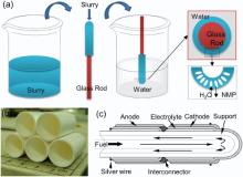
Commercially available TZP, YSZ, (La0.8Sr0.2)0.95MnO3-δ (LSM) and NiO powders with purity of 99.9% were purchased from Huatsing Power (Kunshan, China) for this study. Polyethersulfone (PESF), N-methyl-2-pyrrolidone (NMP) and microcrystalline cellulose (MC) were used as the polymer binder, solvent and pore-former, respectively, which were purchased from Lanyi Inc. (Beijing, China). The tubular ceramic-support was prepared by phase-inversion method as shown in Fig. 1(a). Firstly, the TZP powder and 10 wt% of MC as pore-former were mixed in ethanol by ball milling for over 24 h. Then, the dried powder was mixed with solution of PESF in NMP and milled to obtain viscous slurry. The slurry was uniformly coated on the surface of a tubular glass rod by flowing down according to its own weight. After that, the glass rod with the coating was immersed in pure water for 20 min to solidify the outer coating layer. The glass rod was removed and the green ceramic tube with an outer diameter of ~16 mm was obtained. After drying, the green ceramic tube was pre-fired at 1100 ° C for 2 h, in order to burn off the organics and provide sufficient strength for handling and brush painting. The wall thickness of the tubular support can be controlled by regulating the viscosity of the slurry used.
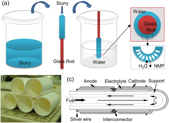 | Fig. 1. Schematic diagram of the preparation of ceramic tubular support (a), the prepared ceramic tubular support (b) and the schematic diagram of tubular ceramic-supported SOFC (c). |
Before applying to the tubular ceramic support, the anode, electrolyte and cathode materials were firstly prepared into slurry by mixing with terpineol, fish oil and ethylcellulose. The NiO-YSZ functional anode layer (equivalent to 50% NiO and 50% YSZ by weight ratio) was coated on the pre-fired ceramic tube using a brush painting method. After drying, the YSZ electrolyte layer was then brush painted on the surface of anode layer, which was then sintered at 1400 ° C for 5 h to form a dense film. The LSM-YSZ composite functional cathode layer (equivalent to 50% NiO and 50% YSZ by weight ratio) and the pure LSM cathode collector layer were in turn applied using brush painting method, followed by firing at 1200 ° C for 2 h. When tested, the tubular ceramic-supported SOFC was sealed on an alumina tube using ceramic paste as sealant (Aramco-552, USA).
The microstructure of the substrate tube and the cross-section of the cells were characterized by scanning electron microscopy (SEM, JEOL JSM-6700F, Japan), before which the sample surfaces were gold plated using the ion sputter (JFC-1600, Japan). The electrochemical properties of the tubular SOFC were tested by a four-probe method with wet hydrogen or methane (3 mol% H2O) as fuel and ambient air as oxidant. The flow rate of the fuel was set as 50 mL/min for single cell and 80 mL/min for SIS two-cell-stack. The cell performance was evaluated by heating the tubular SOFC sample in an electric furnace at three different temperatures: 750, 800 and 850 ° C. The anodic and cathodic currents were collected using silver wires as the current leads with silver paste applied over the electrode surfaces for better electrical contact. An IM6 Electrochemical Workstation (ZAHNER, Germany) was employed to measure the cell electrochemical performance.
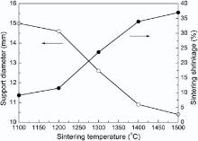
Taking the practical application into account, the basic requirements of a substrate for SOFCs include satisfying physical strength and sufficient porosity. In fact, these two indicators usually present opposite effects. The presence of the pores will be beneficial to gas phase transport, but it may be very detrimental to the mechanical stability of the ceramic tubular support. Thus, appropriate preparation conditions need to explore for the balance of physical strength and porosity. Fig. 2 shows the diameter and shrinkage of ceramic tubular support at different sintering temperature. It can be seen that the shrinkage of ceramic tubular support increases with the sintering temperature. When sintering temperature is as high as 1400 ° C, the shrinkage is up to about 34%. Through multiple times comparative test, we choose to pre-fire the support at 1100 ° C to obtain certain physical strength which is in favor of the subsequent fabrication of SOFCs. It is found that the pre-firing at 1100 ° C does not affect the densification of electrolyte at the sintering temperature of 1400 ° C.
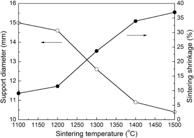 | Fig. 2. Diameter and sintering shrinkage of ceramic tubular support. The shrinkage is defined as the change of diameter in a certain temperature compared with the unsintered tubular support. |
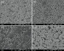
Generally, the inorganic ceramic membrane fabricated by phase-inversion method presents a typical three-tier structure, namely, the outer finger-like pore layer, the intermediate macrovoid layer and the inner dense layer[18]. However, the presence of dense layer will hinder the transport of fuel gas. Therefore, pore-former is used to produce porous outer and inner surface structure. The surface microstructures of ceramic tubular support before sintering and after sintering at 1400 ° C are shown in Fig. 3. It can be seen that the outer surface of tubular support exhibits an interesting structure with grooves before sintering, which is consistent with the observation in previous work[19]. The inner surface has less porosity and is relatively smooth compared with the outer surface since there is little or even no contact with water. After sintering at 1400 ° C, both the outer and inner surfaces of tubular support are porous, which is favorable in fuel gas transport.
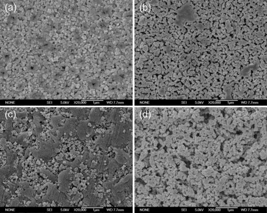 | Fig. 3. SEM images showing the surface microstructure of ceramic tubular support: (a) the outer surface before sintering; (b) the outer surface after sintering at 1400 ° C; (c) the inner surface before sintering; (d) the inner surface after sintering at 1400 ° C. |
Through phase inversion method, several kinds of pores formed within the tubular support as well as with the aid of pore former. The porous structures of the tubular support before sintering and after sintering at 1400 ° C are shown in Fig. 4. It can be found that the finger-like pores are uniformly distributed in the outer layer with a thickness of less than 100 µ m. The intermediate macrovoids are closely interlinked with the outer finger-like pore layer with a range of throughout almost the entire support. During the phase inversion process, the NMP solvent rapidly exchanges with the non-solvent, and plenty of pores are subsequently formed within the support[20]. With the missing of NMP solvent, the PESF solute gradually precipitates and solidifies (as shown in Fig. 4(b)) as well as the solidification of slurry. Due to the diffusional flows of solvent from the polymer solution surrounding the PESF nuclei, the macrovoids are formed as shown in Fig. 4(b)[21, 22]. During subsequent sintering, the pore former MC, PESF and the residual NMP will be lost by ignition, causing various pores in both internal and external surfaces of the tubular support. It can be seen from Fig. 4(c) and (d) that the gas-permeable macrovoids remain after sintering at 1400 ° C, indicating that the tubular support is suitable for SOFC support in regard of gas permeability.
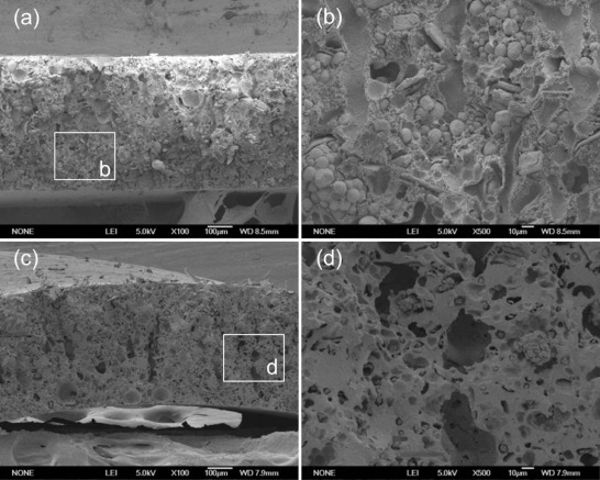 | Fig. 4. Cross-sectional SEM images showing microstructures of the tubular support: (a) before sintering; (b) close-up view of (a); (c) after sintering at 1400 ° C; (d) close-up view of (c). |
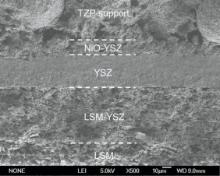
Fig. 5 shows the cross-sectional micrograph of tubular ceramic-supported SOFC. It can be seen that the YSZ electrolyte film appears to adhere well to the porous anode and cathode with a thickness of ~35 µ m. The thickness of functional anode layer and cathode layer are about 20 µ m and 80 µ m, respectively. The tubular support is excellently connected to the NiO-YSZ functional anode layer. It can also be seen from Fig. 5 that the YSZ electrolyte film is very dense, which will prevent the leakage of the fuel during the cell performance test.
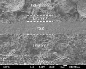 | Fig. 5. Cross-sectional micrograph of tubular ceramic-supported SOFCs. |
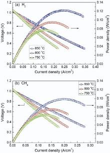
Operated with hydrogen or methane as fuel and ambient air as oxidant, the I-V and I-Pcharacteristics at 750-850 ° C of single cell are shown in Fig. 6. The open circuit voltage (OCV) is up to 1.03 V and 1.02 V at 850 ° C when fed with wet hydrogen and methane, respectively. These values, close to the theoretical ones, confirmed that a gas-tight YSZ electrolyte layer is achieved, as also indicated by the SEM micrographs in Fig. 5. Fueled by wet hydrogen, the maximum power densities generated by the single cell are 77, 95 and 122 mW/cm2 at 750, 800 and 850 ° C, respectively. Although the power densities of this tubular ceramic-supported SOFCs are relatively low, they are still much higher than those of the electrolyte-supported micro-tubular cells using YSZ as electrolyte measured at the same temperature (18 mW/cm2 at 800 ° C)[6]. When measured using wet methane as fuel, the maximum power densities generated by the single cell are lowered to 62, 75 and 100 mW/cm2 at 750, 800 and 850 ° C, respectively. This is mainly attributed to the lower catalytic effect for methane than hydrogen of the Ni anode.
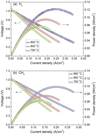 | Fig. 6. I-V and I-P curves of single cell at different test temperature using wet hydrogen (a) and methane (b) as fuel at a flow rate of 50 mL/min. |
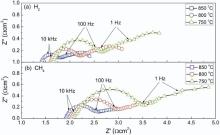
Large resistance is the main reason for the low power density. Fig. 7 shows the AC impedance spectra of single cell at different temperatures under open circuit potential conditions. The total resistance, ohmic resistance and interfacial polarization resistance are determined from the impedance spectra. The intercepts of the impedance arcs on the real axis at high frequencies correspond to the ohmic resistance, while the overall size of the arcs is attributed to the polarization resistance. The total resistance is the sum of ohmic resistance and polarization resistance. It can be seen from Fig. 7 that the contribution of ohmic resistance to the total cell resistance was quite high, which will directly lead to the consumption of open circuit voltage. The overall cell ohmic resistance is strongly influenced by the thickness of electrolyte and electrode[23], the contact condition between cell components[24] as well as the current route caused by different location of current collection[25, 26, 27, 28]. In this work, the large thickness of the electrolyte layer should account for the high ohmic resistance, which can be seen in Fig. 5. Besides, current collection from the anode was only made from one edge of the anode in the present cell design. As analyzed by the simulation study[29], the electrons must migrate through the entire electrode to the external circuit. The long current path generates high ohmic resistance along with the tubular SOFC. For further improvement of tubular cell performance, therefore, the current collecting problem at the anode side needs to be solved.
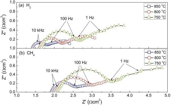 | Fig. 7. Nyquist plots for the single cell under OCV conditions at different test temperature. |
It is generally accepted that the high-frequency arc is attributed to the fuel oxidation reaction at three-phase boundaries (TPBs) of the anode (i.e. activation polarization of the anode) and the oxygen reduction reaction at TPBs of the cathode (i.e. activation polarization of the cathode), and the low-frequency arc is associated with the concentration polarization of the tubular support. It can be seen from Fig. 7 that the concentration polarization of the cell was relatively high no matter if fueled with hydrogen or methane. There could be a couple of possible reasons for the high concentration polarization. In the present work, it is likely that the low open porosity (about 20% determined by Archimedes' method) due to high sintering shrinkage should account for the high concentration polarization despite a good total porosity of the tubular ceramic support (Fig. 4). In addition, to ensure good mechanical strength of the cell, the tubular TZP support layer had a thickness of 400-500 µ m (Fig. 4), which is fairly large compared to a thickness of 150-300 µ m for the commonly used anode supports[16]. The thick TZP support may result in a poor diffusion of gaseous species. Thus, the porosity or the thickness of tubular support needs to be optimized in further studies. It can also be seen from Fig. 7 that the activation polarization at high-frequency under wet methane is significantly higher than that under wet hydrogen. This could be the main reason for the cell power density difference under these two different fuels.
In the present work, a short cell stack was fabricated using silver paste to connect cells in series. Fig. 8 presents the performance of the SIS two-cell-stack operated at 850 ° C using wet hydrogen as fuel at a flow rate of 80 mL/min and ambient air as oxidant. The measured OCV of the two-cell-stack was found to be very close to the theoretically calculated value (about 2.2 V predicted from the Nernst equation)[30], suggesting that the YSZ electrolyte is sufficiently dense and the interconnector works properly. The two-cell-stack exhibits a maximum output power of 0.28 W at 850 ° C. This demonstrates that the present tubular design could be expected to deliver a higher voltage for longer support with more SIS cell stacks, despite the slightly lower power densities than those of the conventional anode-supported micro-tubular SOFCs with similar component materials.
 | Fig. 8. I-V and I-P curves of the two-cell-stack at 850 ° C using wet hydrogen as fuel at a flow rate of 80 mL/min and ambient air as oxidant. |
In this paper, we report the fabrication and characterization of tubular ceramic-supported SOFCs produced by a low cost and simple process involving phase-inversion, brush coating and co-sintering. The tubular support fabricated by the phase-inversion method presents a typical three-tier structure, namely, the outer finger-like pore layer, the intermediate macrovoid layer and the inner dense layer. However, both surface and inside are porous after sintering at 1400 ° C, proving that the tubular support is gas-permeable even with a sintering shrinkage of about 34%. The open circuit voltage of both single cell and cell stack are close to the theoretical one, indicating that a gas-tight YSZ electrolyte layer can be achieved through co-sintering with tubular support and anode layer. The maximum power density of single tubular SOFC is 100 mW/cm2 and 122 mW/cm2 at 850 ° C when fed with wet methane and hydrogen, respectively. The present tubular design could be expected to deliver a higher voltage for longer support with several SIS cell stacks. The current collection, thickness of electrolyte and gas permeability of tubular support should account for the large total resistance. Thus, optimization of the tubular ceramic-supported SOFC should be performed in a further study.
The authors gratefully acknowledge the financial support from the National Basic Research Program of China (973 Program, No. 2012CB215404), the National Natural Science Foundation of China (Nos. 51261120378 and 51402355), Beijing Natural Science Foundation(No. 2154056) and Specialized Research Fund for the Doctoral Program of Higher Education (SRFDP, No. 20130023120023).
The authors have declared that no competing interests exist.
| [1] |
|
| [2] |
|
| [3] |
|
| [4] |
|
| [5] |
|
| [6] |
|
| [7] |
|
| [8] |
|
| [9] |
|
| [10] |
|
| [11] |
|
| [12] |
|
| [13] |
|
| [14] |
|
| [15] |
|
| [16] |
|
| [17] |
|
| [18] |
|
| [19] |
|
| [20] |
|
| [21] |
|
| [22] |
|
| [23] |
|
| [24] |
|
| [25] |
|
| [26] |
|
| [27] |
|
| [28] |
|
| [29] |
|
| [30] |
|