

Effect of Reverse-threaded Pin on Mechanical Properties of Friction Stir Lap Welded Alclad 2024 Aluminum Alloy
[Yumei Yue1 , Zhengwei Li1 , Shude Ji1, 2, *  , Yongxian Huang
2 , Zhenlu Zhou1 ]
, Yongxian Huang|
|


In friction stir welding (FSW), tool geometry plays an important role in joint quality. In order to improve mechanical properties of friction stir lap welding (FSLW) joint, a tool with a reverse-threaded pin was designed in the present study. Using 2024-T4 aluminum alloy as the research object, tools with the full-threaded pin and reverse-threaded pin were used in FSLW. Results showed that, when using the same parameter combination, FSLW joint using the reverse-threaded pin owned bigger effective sheet thickness (EST), bigger lap width and better lap shear failure strength. Compared with the full-threaded pin, fracture mode of the FSLW joint changed from shear fracture mode to tensile fracture mode when the reverse-threaded pin was used. Fracture morphologies presented ductile fracture.
As a solid state joining technology, friction stir welding (FSW) owns advantages of lower stress, smaller distortion, less defects and lower energy consumption. In recent years, FSW has shown a promising engineering application in aerospace and transportation industries[1]. Besides friction stir butt welding, another important joint configuration is friction stir lap welding (FSLW). Owning to the same advantages as the butt welded joints, FSLW has attracted more and more attention[2, 3, 4, 5].
So far, investigations about FSLW mainly focused on temperature, microstructure and mechanical properties[6, 7, 8, 9, 10]. Yazdanian et al.[6] found that higher temperature is beneficial for the increase of the stir zone (SZ) at the lower plate. Liu et al.[7] reported that increased heat input led to more dispersed alclad in SZ. Using FSLW, Song et al.[8] welded 2024 and 7075 aluminum alloys and found that welding parameter largely determined the hook geometries. In fact, similar to friction stir butt welding, material flow behavior largely influences the joint quality of FSLW[9, 10, 11, 12]. Therefore, tool geometry, which mainly determines the material flow behavior during welding, becomes the hotspot at home and abroad[13, 14, 15]. Yin et al.[13] showed that tool with a flat/threaded pin is beneficial for the material mixing between the upper and the lower plates, thereby increasing joint strength. Yang et al.[14] pointed out that the triangular pin could effectively suppress the hook on the retreating side (RS) due to enhanced horizontal material flow.
In our previous study[15], it was found that the thread on the rotating pin can accelerate material flow behavior during FSW. Besides, the tool rotating direction during welding and the thread morphology can drive the plastic material to flow upward or downward. For lap joint, more material flow toward the lap interface may increase the material mixing between the upper and the lower plates. Therefore, in the present study, a tool with a reverse-threaded pin was designed. The full-threaded pin was used to compare with the reverse-threaded pin. Cross-sections, lap shear failure load and fracture modes of the lap joints were mainly studied.
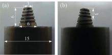
Tools with the full-threaded pin and the reverse-threaded pin used in the experiment are shown in Fig. 1. As shown in Fig. 1(a), the tool consists of a concentric structure shoulder and a full-threaded pin. The diameter of the shoulder is 15 mm. Root and tip diameters of the pin are 6 mm and 3 mm, respectively. Length of the right-hand thread pin is 6 mm. For the reverse-threaded pin, the pin tip has left-hand thread and the pin root has right-hand thread. The thread reverses at the middle location of the pin. Dimensions of the shoulder and other parts are the same as the full-threaded tool.
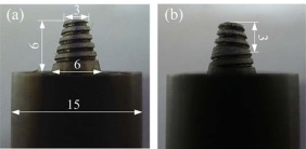 | Fig. 1. Tools used in the experiment: (a) tool with the full-threaded pin; (b) tool with the reverse-threaded pin. |
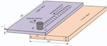
Alclad 2024-T4 aluminum alloy was chosen as the base material (BM). The thickness of the alclad layer is 0.1 mm. Thicknesses of the upper and lower sheets were 3 mm and 5 mm, respectively. Dimensions of the sheets to be welded were 300 mm × 140 mm, which were cleaned with emery paper prior to welding. Two sheets were lap combined with an overlap area of 300 mm × 50 mm and then were welded along the center line of the overlap area, as shown in Fig. 2. In the present study, all specimens were welded according to configuration B, which means that the RS bears the main load during lap shear test, as shown in Fig. 2. The FSW-3LM-4012 machine was used during the experiment. Rotating speed of 600 r/min and welding speed of 50 mm/min were adopted. During the FSLW experiment, tilting angle of the tool axis was 2.5° . Shoulder plunge depth was chosen as 0.2 mm.
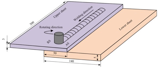 | Fig. 2. Schematic of FSLW in the present study. |
After welding, metallographic samples and lap shear specimens were cut using an electrical discharge cutting machine. Width of the lap shear specimens is 40 mm. After being burnished, polished and etched with Keller's reagent, metallographic analysis was carried out by optical microscopy (OM, Olympus-G71). Lap shear tests were performed on a computer-controlled universal tensile testing machine. A constant speed of 5 mm/min was used during the tests. Each lap shear failure load was averaged by the results of three specimens. After lap shear tests, fracture positions of the specimens were observed using a stereoscopic microscope (ZSA403) and fracture surfaces were analyzed by scanning electron microscopy (SEM, SU3500).
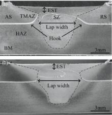
Fig. 3 shows the cross-sections of the FSLW joints using the two different tools. It can be seen that hook forms at both the advancing side (AS) and the RS. Hook at the AS mainly bends upward along the thermal-mechanically affected zone (TMAZ)/SZ boundary, while hook at the RS firstly shows an upward bending trend and then extends into the SZ. During FSLW, material also shows vertical flow besides flowing as the rotating pin, leading to bending morphology of the lap interface, which is called hook. Hook geometries significantly affect the joint quality[16]. At the RS, the shoulder-driven material flows as the rotation of the shoulder. Afterwards, it is released at the back of the shoulder and finally flows into the cavity left by the pin's forward movement. The pin-driven material and shoulder-driven material converge at the SZ, leading to the hook at RS. For the full-threaded pin in Fig. 1(a), material flows downward along the pin when the tool rotates anti-clockwise. At the joint bottom, the released material forces plastic material of TMAZ at the lower sheet to flow upward. Therefore, the lap intersection and material in TMAZ show the up-bending morphology at AS. For the reverse-threaded pin in Fig. 1(b), the right-hand thread plunged into the upper sheet drives the material of the upper plate to flow downward. The left-hand thread plunged into the lower sheet drives the material of the lower plate to flow upward. The two materials converge at the lap interface. Therefore, it can be concluded that hooks bend upward on both joints while hook height is bigger on the joint using the full-threaded pin. Lap width of the joint using the reverse-threaded pin is much bigger than that of the full-threaded pin, as shown in Fig. 3.
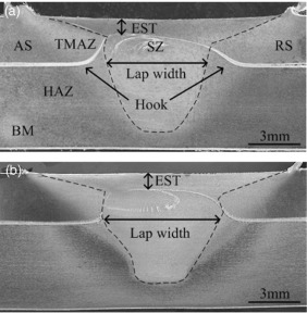 | Fig. 3. Cross-section of the FSLW joints using different tools: (a) full-threaded pin; (b) reverse-threaded pin. |
Without other welding defects, hook, which easily leads to stress concentration, plays an important role in joint strength. Effective sheet thickness (EST) and SZ lap width can be used to quantitatively describe effects of hook on lap joint strength. EST (in Fig. 3) refers to the minimum distance from the hook tip to the top surface of the upper sheet. Lap width (inFig. 3) refers to the width of the bonding area from AS to RS, as shown in Fig. 3. Compared with the reverse-threaded pin, joint using the full-threaded pin owns severer bending hook, leading to smaller EST (Fig. 3(a)). When using the reverse-threaded pin, plastic materials of both the upper and the lower plates flow toward the lap interface, resulting into bigger lap width (Fig. 3(b)).
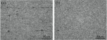
In both FSW and FSLW, microstructure of the SZ plays an important part on welding quality[17]. During FSLW, material temperature is definitely higher than its recrystallization temperature even if it is much lower than the melting point[18]. Therefore, with the stirring action of the rotating tool, dynamic recrystallization happens and fine and equiaxed grains can be observed in SZ. In general, uniform and finer grains distribution always results in better strength and higher hardness. On the contrary, non-uniform grains of the SZ leads to poor weld strength. Fig. 4 shows the microstructure of the SZ using different tools. It can be seen that compared with grains shown in Fig. 4(a), uniform and refiner grains are observed on FSLW joint using the reverse-threaded pin. When the reversed-threaded pin is used, both materials of the upper and the lower plates flow toward the lap interface, leading to enhanced material flow behavior. Higher flow velocity is beneficial in obtaining bigger strain and strain rate of the material in SZ, resulting in finer grains, as shown in Fig. 4(b).
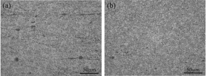 | Fig. 4. SZs of the FSLW joints using different tools: (a) full-threaded pin; (b) reverse-threaded pin. |
Fig. 5 shows the microstructures of TMAZ on the upper sheet using the two different tools. Having undergone both thermal cycle and mechanical stirring during FSLW, materials in the TMAZs are characterized by highly distorted morphology. As shown in Fig. 5(a), grains of TMAZ using the full-threaded pin show a slightly upward flow trend. By contrast, grains of TMAZ using the reverse-threaded pin show a relatively flat but slightly downward flow trend (Fig. 5(b)). The formation of the TMAZ is much like that of the hook. When using the full-threaded pin, more plastic materials flow downward and released at the joint bottom. Therefore, the upward driving force at TMAZ is bigger and the grains in TMAZ show upwards flow direction. On the contrary, upward driving force using the reverse-threaded pin is much smaller. Therefore, at the upper sheet, by the forging force of the shoulder, TMAZ shows a relatively flat but slightly downward flow trend, as shown in Fig. 5(b).
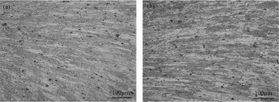 | Fig. 5. TMAZs of the FSLW joints using different tools: (a) full-threaded pin; (b) reverse-threaded pin. |
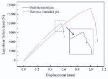
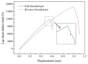
Table 1 shows the lap shear failure loads of the FSLW joints using two different tools. It can be clearly seen that the lap shear failure loads using the reverse-threaded pin are much bigger than those using the full-threaded pin. The results agree with the ESTs and the lap widths in Fig. 3. Besides, load-displacement curves of the joints using the full-threaded pin and the reverse-threaded pin are shown in Fig. 6. As shown in Fig. 6, for the joints using the reverse-threaded pin, the curve comes to a sudden drop after reaching the highest load point. For the joint using the full-threaded pin, the curve firstly descends slowly and then extremely quickly. A possible reason for this can be attributed to rather complicated and different bonding strengths of the alclad and BM. Besides, it can be seen that the joint elongation using the reverse-threaded pin is much bigger than that using the full-threaded pin.
| Table 1. Lap shear failure load of the joint using two different tools |
 | Fig. 6. Load-displacement curves of the FSLW joints using two different tools. |
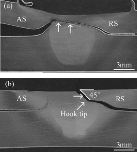
During the lap shear test, two fracture modes were observed: shear fracture and tensile fracture. Shear fracture mode is attained when the full-threaded pin is used. During shear fracture mode, crack mainly propagates along the redistributed alclad in the SZ. The upper and lower plates were separated from each other in the end, as shown in Fig. 7(a). Tensile fracture is attained when the reversed-threaded pin is used. During the tensile fracture mode, a crack firstly initiates at the hook at RS. After reaching the hook's highest point, the crack further owns two propagation paths: one is through the SZ to the joint upper surface; the other is along the hook to the joint center, as shown in Fig. 7(b). In the SZ, the crack propagates along a 45° direction. As shown in Fig. 3(a), on the joint using the full-threaded pin, redistributed alclad at the RS is not sufficiently mixed with the BM. At the AS, alclad shows onion morphology and it is connected with the alclad at the RS. Alclad is composed of pure aluminum alloy, which owns worse strength compared with 2024 Al. Therefore, when bearing external force, a crack more easily propagates along the redistributed alclad, leading to shear fracture mode (Fig. 7(a)). For the FSLW joint using the reverse-threaded pin, hooks at the AS and RS show relatively slight bending morphology and are not connected with each other. At the AS, discontinuous alclad is observed, which is formed due to more sufficient mixture with the BM. Therefore, when the joint bears external load, the crack propagates to the hook tip through the SZ, but not grows further to the joint AS (Fig. 7(b)).
 | Fig. 7. Fracture positions of the FSLW joints using different tools: (a) full-threaded pin; (b) reverse-threaded pin. |
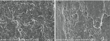
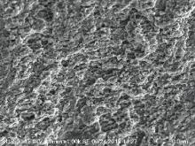
Fig. 8 shows the SEM images of the typical fracture positions (marked in Fig. 7(a)) using the full-threaded pin. As indicated, both the two regions are mainly composed of redistributed alclad, where weak bonding is formed. Therefore, bedded structure with only a few dimples can be observed, as shown in Fig. 8(a) and (b). SEM morphologies in Fig. 8agree with the continuous alclad shown in Fig. 3(a), and the worse lap shear failure properties are given in Table 1. Fig. 9 shows the SEM images of the typical fracture position (marked in Fig. 7(b)) using the reverse-threaded pin. As indicated, plenty of fine dimples exist, indicating a ductile fracture mode. Besides, the fine dimples agree with the finer grains shown in Fig. 4(b).
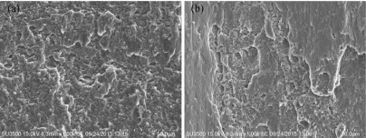 | Fig. 8. Fracture morphologies of the FSLW joints using the full-threaded pin. |
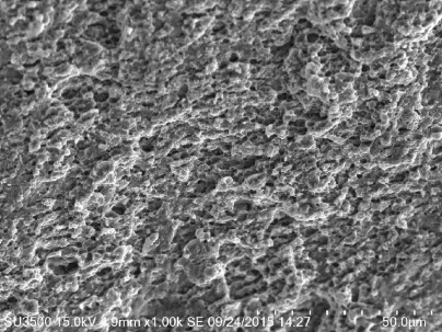 | Fig. 9. Fracture morphologies of the FSLW joints using the reverse-threaded pin. |
(1) The thread on the pin is the main reason for the vertical material flow during FSLW. When the reverse-threaded pin is used, both the materials of the upper and the lower plates flow toward the lap interface, leading to bigger lap width and more sufficient material mixing.
(2) Fracture mode changes from shear fracture mode into tensile fracture mode when the reverse-threaded pin is used. Compared with the full-threaded pin, FSLW joint using the reverse-threaded pin more easily obtains better lap shear failure properties. Fracture morphologies indicate ductile fracture.
This work is supported by the National Natural Science Foundation of China (No.51204111), the Natural Science Foundation of Liaoning Province (Nos. 2013024004 and2014024008), the Project of Science and Technology Department of Liaoning Province(No. 2013222007) and the Aeronautical Science Foundation of China (No. 2014ZE54021).
The authors have declared that no competing interests exist.
| [1] |
|
| [2] |
|
| [3] |
|
| [4] |
|
| [5] |
|
| [6] |
|
| [7] |
|
| [8] |
|
| [9] |
|
| [10] |
|
| [11] |
|
| [12] |
|
| [13] |
|
| [14] |
|
| [15] |
|
| [16] |
|
| [17] |
|
| [18] |
|