


Folic Acid Functionalized Vertically Aligned Carbon Nanotube (FA-VACNT) Electrodes for Cancer Sensing Applications
[Somayeh Zanganeh1, 2 , Fatemeh Khodadadei1, 2, 3 , S. Rafizadeh Tafti1, 2 , Mohammad Abdolahad1, 2, *  ]
]
]
|
|


An electrical cancer biosensor was developed using amine-functionalized vertically aligned carbon nanotubes (VACNTs) conjugated to folic acid (FA) molecules. Specific binding of FA to folate receptor (FR) existing on the membrane of cancer cells assisted their entrapment on VACNTs. For the conjugation of FA to CNTs, amine (-NH2) functional groups were attached to the side walls of the nanotubes by plasma treatment. The amount and shape of entrapped cancer cells on FA-VACNTs were noticeably higher and more uniform than the cells entrapped on bare VACNTs. The comparative signal spike of the FA-VACNTs and VACNTs covered impedance sensor in interaction with the same concentration of lung cancer cells (QUDB) showed sharper response for the functionalized sensor. Moreover, electron microscopy and florescent images as well as impedance diagrams verified the spherical and non-deformed shape of the cells entrapped by FA-VACNT. This sensor would be useful in assaying the cells vitality in time evolution. This device could be applied in diagnostic and time monitoring applications in the field of cancer such as extreme drug resistance assay (EDR).
As malignant cells originate from the body's own tissue, they are difficult to distinguish from the healthy cells. When cancerous transformed cells are undetectable by the body's own immune system, cancer is diagnosed in a patient[1]. A major challenge for cancer diagnosis returns to the ability of malignant cells in denying their true nature. A major challenge in diagnosing cancer as malignant cells is denying their true nature. They express certain surface markers, i.e. proteins embedded in the cellular membrane, at much higher levels than those in a normal tissue[2]. Strong efforts have been applied to identify specific surface proteins and receptors for different types of cancer cells for precise diagnosis[3]. To translate this knowledge into clinical utility, reliable and efficient assaying procedures are required. Label-free methods are being developed to achieve high accuracy of selective detection at lower cost and complexity. Recently, new assays have reported transduction of biomolecular interactions into electrical[4], optical[5], or mechanical[6] signals. Nanostructures are in the range of the most interesting transduction elements. Their great physical properties as well as extreme interactive and efficient surface provide strong response with considerable resolution[7, 8, 9, 10, 11, 12, 13]. Carbon nanotubes (CNTs) as one type of nanostructures with anomalous electrical conductivity, biocompatibility and aspect ratio are capable to apply active nanocontacts with bioanalytes[14, 15]. Consisting of a few layers of carbon, its diameter (~70 nm) is suitable for receptor binding. Such conductive materials can be produced in lengths of several microns, making them capable of providing signal transmission over relatively large distances between the sensing region and the reading pads. As one important application, antibodies specified as cancer biomarkers can be conjugated to the carbon nanotube sidewalls and enhance cell-CNT interaction, which in turn would alter the electrical response of the tubes[16, 17, 18]. Presumably, due to charge transfer and capacitive coupling, readily observed signals can be demonstrated for the detection of the targeted cells.
Reports on cellular sensing with CNT based devices have not yet emerged in great number. Moreover, most CNT based cellular investigations have been conducted on non-oriented nanotubes[19, 20]. Because of loose electrical connections between non-oriented nanotubes and the sensing elements, they were not efficient in electronic biosensor applications. The main applications of non-oriented nanotubes were focused on drug delivery[21, 22, 23] photo thermal therapy[24, 25] and in vivo imaging[26, 27]. Lately, some investigations have been published on applying oriented nanotubes for cellular sensing by electrical and mechanical approaches[28, 29]. For example, direct entrapment of cancer cells on non-functionalized vertically aligned carbon nanotube (VACNT) was investigated[15]. The deformability of cancer cells was the main reason of their grasping by such mechanically deflectable nanotube arrays. The cells were stretched during the entrapment and the shear force applied between the cells and the deflected nanotube was calculated[30]. Also, CNT based electrical biosensors based on signal extraction from the mechanically entrapped cancer cells were fabricated and applied in detecting high metastatic colon cancer cells[4]. The deformability of cancer cells is caused by their various vital states (from G0 to M2), as well as the destructive effect of mechanical stretching on bioelectrical signals of the membrane extracted by nanotubes. The stretched form of mechanically entrapped cancer cells affects their viability in the long run and limits their use for further bioassays, such as electrical drug resistance monitoring (an important therapeutic scenario for a diagnosed patient). The membranes' electrical response of the mechanically stretched cancer cell was affected by the stimulated actin and microtubules due to the cell's cytoskeletal structure having a strong correlation with bioelectrical functions of the membrane[31, 32]. Therefore, apart from just sensing the presence of cancer cells, maintaining the cell's stable shape and function could improve the application of cell-VACNT interactions. Non-deforming entrapment of cancer cells on nanotubes as well as providing the attachment of all cancer cells with different deformability could enhance the electrical sensitivity and maintain the cell's viability for long time monitoring. Functionalizing the nanotubes with suitable cancer biomarkers could be helpful in non-deformed and selective grasping of cancer cells without disturbing the fraction of their entrapment. If the functionalization does not inhibit the electrical signal transduction from the cells by means of the CNTs, it would also be a great choice in developing cell based electrical biosensors.
Folic acid (FA) is one of the best specific biomarkers for cancer cell targeting used in many analytic and therapeutic experiments[33]. The utility of FA in these applications has arisen primarily from some parameters such as: its ease of conjugation to both therapeutic and diagnostic agents, its high affinity to the folate receptor (Kd = 10-10 mol/L) even after conjugation to therapeutic/diagnostic cargo and the limited distribution of folate receptor (FR) in normal tissues. Here we introduce FA functionalized VACNT (FA-VACNT) based electrical biosensor to enhance the fraction of entrapped cancer cells by the assistance of FR existing on their membrane. FA was conjugated to amine functionalized VACNT (NH2-VACNT) by carbodiimide mediated amide bond formation between the carboxylic acid groups of FA and the amino groups of VACNTs. The amount and shape of entrapped cancer cells were investigated and compared with non-functionalized VACNT. Furthermore, we presented the comparative signal spike of FA-VACNT and VACNT covered impedance sensors in interaction with lung cancer cells (QUDB) with positive expressing folic acid receptors.
Transmission electron microscopy (TEM) and Fourier transform infrared spectroscopy (FTIR) analyses were proposed to elaborate the FA binding to the side walls of nanotubes. Field emission scanning electron microscopy (FE-SEM) images as well as electrical impedance responses of the fabricated sensor were evaluated to compare the efficiency of FA-VACNT and VACNT in cell entrapment and sensitivity.
The CNT based biosensor fabrication process (schematically presented in Fig. 1(a)) was initiated by coating the Si surface with a thermally grown SiO2 layer, followed by depositing a thin film of Ni as a catalyst for CNT growth. Subsequently, patterning Ni using standard photolithography was conducted. Finally, the sample was placed in a direct-current plasma enhanced chemical vapor deposition (DC-PECVD) reactor to grow VACNT arrays on desired places. A mixture of H2 and C2H2 gases at a pressure of 133-665 Pa (1-5 Torr), temperature of 650 ° C, and plasma power density of 5 W cm-2 was employed for CNT growth. The length and diameter of the nanotubes ranged from 2 to 12 µ m and from 20 to 75 nm, respectively. Fig. 1(b) represents the FESEM image of the CNT biosensor. Highly ordered CNTs have been achieved with desired patterns and geometries.
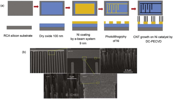 | Fig. 1. (a) Schematic of the fabrication process for VACNT based biosensor. After patterning the Ni catalyst on passivated Si substrate, the nanotubes have been grown on desired regions by DC-PECVD system. (b) FE-SEM images of the fabricated biosensor. Fine vertically aligned nanotubes are observed in desired places. The mean width of the tubes is about 70 nm. |
Amine functionalization of VACNTs was carried out using a double barrier discharge (DBD) plasma system. Fig. 2 represents the diagram of the plasma system and the process for amine functionalization. As shown in Fig. 2(a), the DBD plasma reactor consists of a function generator (Pintek FG-32, Taiwan) connected to a high voltage amplifier (TREK 10/40A, USA). Two mass flow controllers (MFCs, Unit UFC-7300, USA) were used to adjust the flow of He and Ar gases to the reactor. The DBD plasma reactor consisted of a quartz glass with 2.0 mm in thickness as a dielectric barrier. Two stainless steel rods were used as grounded and high voltage electrodes. The gap between the VACNTs and the dielectric barrier was 2.0 mm. A strip heater was used to heat the reactor to 200 ° C. According to our previous experiment[34], the highest quantity of functional groups was obtained at plasma voltage of 9 kV, frequency of 2.6 kHz and chemisorption temperature of 200 ° C. Initially, the flow rate of He was set to 60.0 cm3 min-1, and the DBD plasma reactor was turned on for 6 min. After treatment of VACNT by helium plasma, to obtain the amine-functionalized VACNT (NH2-VACNT), a flow of 30% ammonia in He (18.0 cm3 min-1) was passed through the reactor at 200 ° C for 1 h.
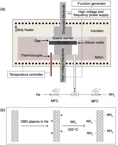 | Fig. 2. (a) Schematic diagram of the experimental setup employed for DBD plasma treatment for the functionalization of CNT. The sample has been located between the electrodes under the quartz barrier. Also the gases have been flown from the bottom of the chamber. (b) The process for activation of CNT in helium plasma and functionalization of the activated CNT by amine groups. Stars (* ) show the excited species produced on CNT surface by the activation process. |
2.3 mg of FA was mixed with 1 mg of 1-ethyl-3-(3-dimethylaminopropyl) carboiimide (EDC) and 1.5 mg of N-hydroxy-succinimide (NHS) in a 10 mL phosphate buffer solution (PBS, pH 7.5) at room temperature and stirred for 15 h. Subsequently, NH2-VACNT was suspended in the reaction mixture at room temperature and stirred for 24 h. The product was washed with ultrapure water multiple times to remove unreacted reagents and then dried at room temperature.
MRC-5 and QUDB cell lines used in this study were isolated from human lung normal and carcinoma tumors, respectively. These cells were obtained from the standard cell banks of Iran and maintained at 37 ° C (5% CO2, 95% air) in RPMI-1640 medium (Sigma 8758). The culture media has been supplemented with 5% fetal bovine serum (Gibco) and 1% penicillin/streptomycin (Gibco) as growth supporter and antibiotic, respectively. The fresh medium was replaced every other day. Cells were then detached from the culture flask by trypsin (Gibco) and flown on the surface of VACNT and FA-VACNT arrays with similar concentrations by microfluidic pump.
The nature of surface functional groups was investigated using FTIR spectroscopy. FTIR analysis confirmed successful amine functionalization and FA conjugation to VACNTs. The spectrum of the FA-NH2-CNTs can be seen in Fig. 3(a). Bare CNTs displayed no significant peak due to the high transmittance of π -electron structure of symmetric carbons in comparison with functionalized nanotubes (not shown in the figure). A weak band corresponding to the characteristic aromatic rings is visible at ~1600 cm-1 (C=C stretching)[35]. The weak C-H stretching and bending modes are due to defects in the bare CNTs structure. NH2-CNTs trace shows C-H symmetric and antisymmetric stretching modes at 2856 and 2926 cm-1, C-N stretching modes in the range of 1050-1400 cm-1, and the N-H bending mode at 1635 cm-1, which are strong evidence of the VACNTs functionalization by primary amine groups[36]. The broaden O-H stretch, known to be the dominant feature in the range of 3000-3500 cm-1, covers the primary amine band (N-H stretch). The FTIR spectrum of FA-NH2-CNTs displays all the characteristic bands of NH2-CNTs. Presence of two peaks at 1530 and 1590 cm-1, corresponding to formation of amide bonds (N-H amide band II) between the amino group of NH2-CNTs and the carboxyl group of FA[37, 38, 39, 40]. Furthermore, the intensified peak at 1400 cm-1corresponds to the aromatic ring stretch of the pteridine ring and ρ -amino benzoic acid moieties of FA, which is another indication for successful formation of FA-NH2-CNTs[36, 41].
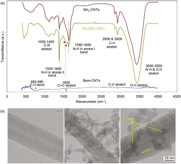 | Fig. 3. (a) FTIR spectra of bare CNTs, NH2-CNTs and FA-NH2-CNTs. Additional N-H amide bend between 1500 and 1640 cm-1 is the main change induced in FTIR diagram of CNT after FA functionalization. No observable N-H bonds were measured in bare CNTs. (b) TEM images of (b1) bare and (b2 and b3) FA conjugated to the nanotubes. The trace of FA agents on the wall of CNTs is distinguishable based on their different gray color. |
TEM images of the bare CNTs (Fig. 3(b1)) are mostly identical for all obtained materials. After functionalizing NH2-VACNTs with FA in PBS pH 7.5 (Fig. 3(b2)), the product was washed with water to remove unreacted FA and then dried at room temperature. FA as a surface active biological substance was well dispersed under physiological pH ~ 7.5 due to its surface charge density[42]. After being dried, it would agglomerate onto the surface of CNTs. It is clearly observed from Fig. 3(b3) that large quantities of FA agglomerates were conjugated on the CNTs surface and even shielded their interior structures, which indicated the great binding affinity of FA to carbon sheets[40, 43, 44]. The functionalization with FA was based on the reaction with sidewalls. Nevertheless, the functionalization with these compounds did not introduce any defects beyond those already existing on the structure of the CNTs. The length and diameter of these materials were not influenced by the functionalization process. All examined CNTs were multi-walled carbon nanotubes of high purity with Ni filled internal channel.
3.1.1. Raman spectroscopy of VACNT array
The Raman spectrum of MWCNTs and functionalized CNTs by amine groups shown inFig. 4 presented a D-band (disordered) and a tangential band (graphitic) at 1343 cm-1 and 1578 cm-1, respectively. The D band was reported to be normally located around 1348 cm-1 and the G-band at around 1564 cm-1[29]. The exact location of the band strongly correlates with crystallinity of the nanotubes, as the intensity of the D band increases by decreasing the level of crystallinity of the nanostructure. The crystallinity of carbon nanotubes is determined by comparing the disordered (D) and the graphitic (G) bands. So, the higher ratio (ID/IG) would lead to a less crystalline structure. In our samples, as seen from Raman spectroscopy, such ratio was less than 1, indicating the great physical and crystalline properties of the nanotubes. Also functionalization did not induce any perturbation in crystalline structure of the nanotubes.
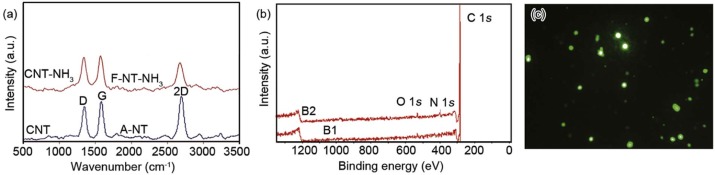 | Fig. 4. (a) Raman spectra of VACNT grown by DC-PECVD system. The D and G bands located at 1343 cm-1 and 1578 cm-1, respectively. The intensity of G bands is higher than D ones, which indicated the great crystalline structure of the tube. Also Raman result of functionalized nanotubes by amine groups (F-NT-NH3) showed no perturbation in crystalline structures of the tubes. (b) XPS spectrum of MWCNT and FAMWCNT structures. Presence of N1s peak corroborates the functionalization. (c) GFP tagged florescent image of cancer cell trapped on CNT arrays. The presentation of green color indicated the vital state of cancer cells after entrapment. |
Also, Fig. 4(B1) indicated the X-ray photoelectron spectroscopy (XPS) spectrum of MWCNT. It showed the C1s peak at 283.3 eV. Fig. 4(B2) presented the XPS of FA-functionalized MWCNT. The N1s peak appeared at 397.88 eV as the main indication of FA functionalization [45].
3.1.2. Zeta potential of MWCNT and FA-MWCNT
Zeta potential of MWCNT and FA-MWCNT (Fig. S1 in Supporting Information) indicated that the modification of MWCNTs with FA makes the zeta potential of our nanostructures more positive, being helpful for the attachment of cancer cells, which have negative charges in their membrane.
3.1.3. Biocompatibility of carbon nanotubes
Many biological assays, reported previously by us and other groups, confirmed the biocompatibility of CNTs. MTT (3-(4, 5-Dimethylthiazol-2-Yl)-2, 5-Diphenyltetrazolium Bromide) and LDH (lactate dehydrogenase)[4] investigations indicated more than 90% biocompatibility of epithelial cancer cells after interaction by CNTs grown by Ni catalyst. Moreover the florescent image taken from live cancer cells tagged by green-fluorescent protein (GFP) before entrapping on CNT arrays for 1 h after entrapping on CNT arrays indicated the live state of grasped cells.
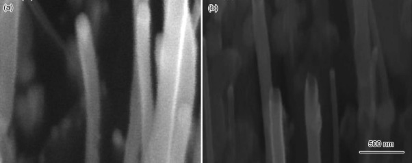
The presence of nickel on the top side of the CNTs could be related to the tip-growth mechanism in our PECVD unit. Although Ni acts as a catalyst during the growth, it would be coated with multi-layers of carbon and hence Ni would not directly interact with cells. The round and smooth shape of the tips could protect the cell membranes from being torn by the sharp side walls of nanotubes. In addition, it favorably contributes in enhancing electrical signal transmission along the CNTs interacted to cell membrane. The hemispherical shape of Ni catalyst (as shown in Fig. 5) would lead to a smooth penetration into the cell membrane and extract direct signal from the cell.
 | Fig. 5. High magnification SEM images of (a) Ni/MWCNT in which the Ni has a dome shape. (b) The sharp side walls of Ni removed MWCNT. |
Contrary to Ni/MWCNTs, Ni-removed CNTs exhibited reduced biocompatibility. This would be initiated from the harsh shape of Ni removed CNT tips, which can damage the cell membrane[46]. We have also observed that removing the nickel from the top side of the CNTs would lead to weaker electrical signals due to the lack of Ni as signal transmitter. As a result, Ni played crucial role in mechanical, biological, and electrical parameters of CNT-ECIS (electric cell impedance sensing).
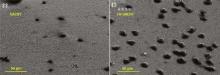
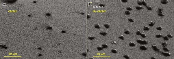
Fig. 6 presents the SEM images of entrapped lung non-small cell carcinoma (QUDB) on bare (Fig. 6(a)) and FA functionalized (Fig. 6(b)) VACNT arrays. The cells' fraction entrapment was dramatically enhanced from 300 to 1150 per mm2. As the VACNTs were functionalized with FA, great interaction was applied between folate receptor on the membrane of QUDB cells and FA-VACNT.
 | Fig. 6. SEM images of QUDB cell entrapped by (a) VACNT and (b) FA-VACNT arrays. The fraction of entrapped cells on functionalized surface is considerably higher than the non-functionalized one. |
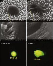
Moreover, as illustrated in higher resolution FE-SEM images (Fig. 7), the entrapped cell on FA-VACNTs maintained its natural spherical shape without any mechanical stress (Fig. 7(a)). However, considerable deformation and mechanical stretch was observed in the cells entrapped by non-functionalized VACNT surface (Fig. 7(b)). Such deformation was the main entrapping mechanism of the cancer cells as we reported previously[4]. To evaluate the mechanical stress applied on both cells, we calculated the cell traction force (CTF) of entrapped cells on both types of nanotubes by large deflection mode method[29]. Although the surface of VACNTs was super hydrophobic (contact angle presented in Fig. S2), the cancer cells were grasped by nanotubes because their entrapment was a mechanical process based on cells deformability as discussed previously[15]. The amount of nanotubes involved in entrapping a cell as well as the deflection angles of the grasping nanotube are fundamental parameters to evaluate the traction force. The CTF of a QUDB cell applied on non-functionalized VACNT beams was 7.6 µ N, which was 3.3 times higher than the similar force applied on FA-VACNT surface (2.3 µ N). Sharper deflection of non-functionalized nanotubes was distinguishable in SEM images. To ensure the different geometries of entrapped cells on bare and functionalized VACNTs, we took live florescent images on A/O stained QUDB cells after entrapment on CNTs. As presented in Fig. 7, the shape of live QUDB cell entrapped on FA-VACNT was remarkably spherical and similar to SEM images (Fig. 7(c)). Meanwhile observable deformation was noticeable in the image of the cell entrapped by bare VACNT (Fig. 7(d)).
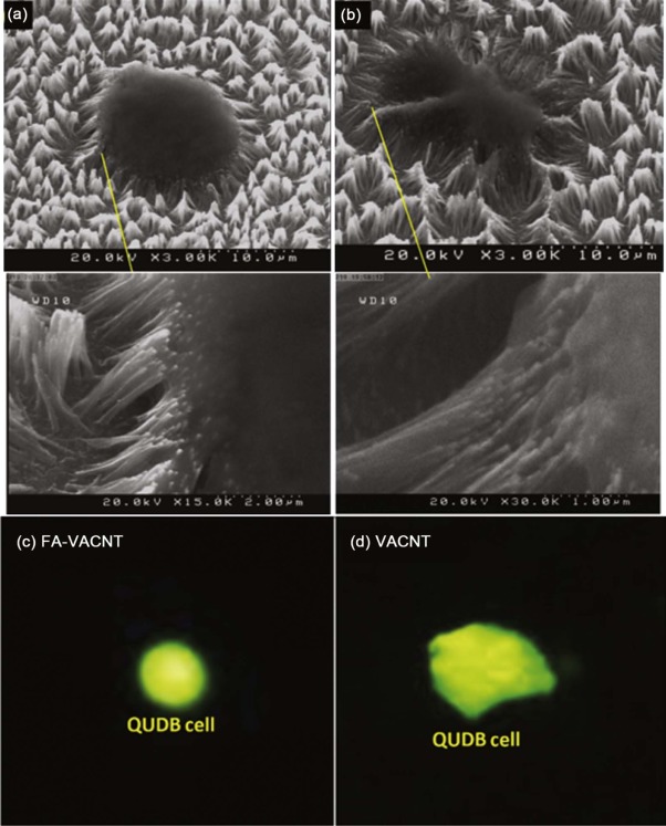 | Fig. 7. FE-SEM images of single QUDB cells entrapped by (a) FA-VACNT and (b) bare VACNT arrays. Cell entrapped by FA-CNT exhibit non deformed shape and maintained its spherical state in contrast to the deformed cell grasped by non-functionalized CNT array. The deflections of nanotubes grasping the cell membrane are observable in higher resolution images. Florescent images of A/O tagged live QUDB cells entrapped by (c) FA-VACNT and (d) VACNT arrays. |
As illustrated in Fig. 8(a), the FA based attachment of cancer cells on nanotubes produced a specific binding to folate receptor of the cell membrane, in which the FA functional groups on the CNTs neither affect the physical shape nor change the cytoskeletal stability of the cell. But in the case of the cells attached on bare VACNTs (Fig. 8(b)), the direct mechanical grasping of the cell by CNT beams induced some non-oriented deformation on the cell.
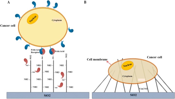 | Fig. 8. Schematics of the binding mechanism (a) between FA-VACNT and folate receptor in QUDB cells and (b) direct grasping of the QUDB cell membrane by bare VACNT and their noticeable deflection after entrapment. |
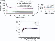
Electrical response of the non- and FA-functionalized VACNT covered impedance sensors is represented in Fig. 9(a). As higher fraction of cancer cells were entrapped on FA-VACNT sensor (Fig. 6(b)), it exhibited further impedance (about 2 times) than bare VACNT based device (mean 6000 Ω vs 1400 Ω ). Also, the cells entrapped by FA-VACNTs showed better viability (discussed above). Hence, the beta dispersion properties (the ability of the cell membrane in blocking the electrical currents flow from the electrodes toward them) of their membrane were greater than the cells entrapped by bare VACNT device. The time evolution of the signals extracted from the cells entrapped by FA-VACNT sensor indicated that the dielectric properties of the membrane, correlated with phase diagram[43], were not induced (Fig. 9(b)). This would be other corroboration for stable vital states of cancer cells entrapped by FA-VACNT sensor. In addition, healthy lung cells (MRC-5) were not entrapped by CNT arrays (as simultaneously reported for normal renal cells before[15]). So the impedance of the sensor exposed by MEC-5 cells was much less than that of the cancerous one (Fig. 9(a)). However because of some folate receptors existed on the membrane of normal cells, the impedance of MRC-5 cells covered FACNT sensor was further than that of non-functionalized sample; such a response was still much less than FA-VACNT sensors exposed by QUDB cells (Fig. 9). The folate receptors of normal cells are much lower than malignant ones[47], so the fraction of MRC5 cells entrapment on FACNT would not be sharply different from non-functionalized CNTs. As presented in Fig. 9(b), time evolution did not induce any changes in the electrical response of entrapped cells on FACNT arrays. The dielectric properties of the membrane, which are strongly related to the phase response of the cells, did not change even after cell attachment of 1 h. This response corroborated the conformal shape of the cells entrapped by FACNT array in contrast to deformed cells on non-functionalized CNTs.
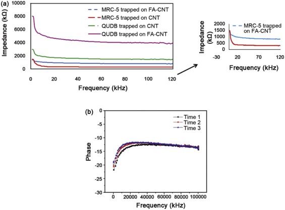 | Fig. 9. (a) Electrical response of entrapped QUDB and MRC-5 cells membrane on FA-VACNT and bare VACNT arrays. The impedance of the devices covered by cancer cells is much higher because of enhanced fraction of cancer cells entrapment on both FAVACNTs and simple VACNTs. (b) Time evolution response of cancer cells attached on FACNT sensor. The signals have been extracted 10 min (Time 1), 30 min (Time 2) and 60 min (Time 3) after entrapment of the cells. |
Here we presented a table from the parameters and performances of FACNT biosensor in comparison with those of other impedance based cell biosensors reported elsewhere (Table 1). It is observable that the sensitivity of FACNT biosensor is higher than other devices. Moreover, the density of attached cells is enhanced with respect to non-functionalized CNT-ECIS. Here, the sensitivity of the sensors is defined as[4]:
Sensitivity(f)=(|Zcell-covered-total(f)|-|Zcell-free-total(f)|)Qcell-1
| Table 1. Comparison between the parameters of FACNT-ECIS and other impedance biosensors |
The sensing time of the sensor is that required for the cells to be attached on the surface. This time is so fast for CNT based ECIS, in which the mechanical entrapment plays a key role in cells attachment. Electrical response time is the time needed to extract electrical signal from attached cells. Also this value is so smaller for CNT-ECIS in comparison with other biosensors.
The time and cell efficiency factors (TEF and CEF, respectively) of the sensor, which corresponds to the best sensitivity of the sensor (S) per time duration for cell attachment on the electrodes (T) and per density of attached cells (D), respectively, are presented inFig. 10. The results indicated the better resolution of FACNT biosensor in comparison with other cell biosensors. FACNT sensor exhibited higher sensitivity in the lower density of attached cells as well as time of attachments.
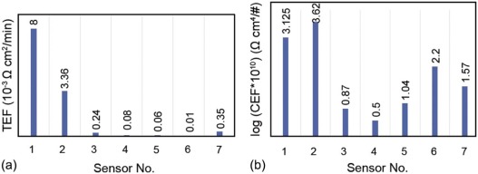 | Fig. 10. Comparative diagrams of (a) CEF and (b) TEF parameters between FACNT-ECIS and other biosensors. Both values are so sharper for functionalized ECIS. |
In addition effect of the radius of nanotubes in the response parameters of FACNT-ECIS was investigated in Fig. S3 in the Supporting Information.
For the next generation of VACNT based electrical cell impedance sensing biosensor, the FA-VACNT-ECIS with better fraction of entrapment as well as great viability of entrapped cells for long time assays would be used in our future work.
In summary, the fraction of cancer cells entrapment on FA functionalized VACNT arrays were observably increased in comparison with bare VACNTs. Also the shape and vital state of the entrapped cells were more stable and non-deformed. Different entrapment mechanisms would be the reason of such achievements. Low mechanical stress applied on the cells bound by their folate receptor on the FA-VACNT, considerably reduced the CTF (more than 3 times) of the cells on nanotubes as calculated. Electrical response of the sensors covered with FA-VACNT electrodes was considerably sharper and the dielectric responses of the entrapped cell membrane were noticeably stable in time evolution. The impedance cell biosensor based on FA-VACNT could be used as a powerful tool in diagnostic and EDR assays in the future.
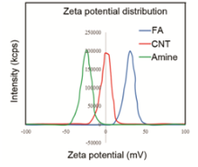
Fig. S1 presented the zeta potential of MWCNT and FA-MWCNT dispersed in ultrapure water and RPMI-1640 medium. The zeta potential analysis reveals that after the functionalization of positive charged FA NPs, the FA-MWCNT hybrids show a positive zeta potential (about18–23 mV) in water. This result indicates that the modification of MWCNTs with FA makes the zeta potential of our nanostructures more positive, being helpful for the attachment of cancer cells which have negative charges in their membrane.
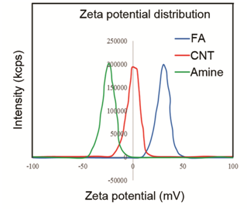 | Fig.S1. Zeta potential distribution of MWCNT and FA-MWCNT. |
To confirm the hydrophobic nature of VACNT surface we investigated the contact angle test presented inFig.S2. The results show the water droplet did not spread on the surface and its angle to the surface was much less than 90°, indicating the hydrophobic nature of the surface.
 | Fig.S2. Contact angle image of VACNT array. |
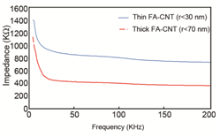
Finally, we have investigated the effect of the CNT aspect ratio in their fraction of entrapment and the response of biosensor. The impedance of the CNT-ECIS covered with thinner CNTs (r<30 nm) was higher than thicker ones (r<70 nm), as shown in Fig. S3. The electrical parameters of these two groups of nanotubes were similar prior to any biological experiments. Thinner CNTs are more elastic and could entrap higher amount of cancer cells resulted in increased impedance of the sensor.
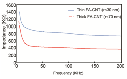 | Fig.S3. The impedance spectrum of entrapped cancer cells on two FACNT-ECIS sensors which were covered with different nanotube diameters (<30 nm and <70 nm) during their fabrication process, measured at different probe frequencies. The tests were investigated at the same cell concentration and experimental parameters. |
Supplementary data to this article can be found online at
The authors have declared that no competing interests exist.
| [1] |
|
| [2] |
|
| [3] |
|
| [4] |
|
| [5] |
|
| [6] |
|
| [7] |
|
| [8] |
|
| [9] |
|
| [10] |
|
| [11] |
|
| [12] |
|
| [13] |
|
| [14] |
|
| [15] |
|
| [16] |
|
| [17] |
|
| [18] |
|
| [19] |
|
| [20] |
|
| [21] |
|
| [22] |
|
| [23] |
|
| [24] |
|
| [25] |
|
| [26] |
|
| [27] |
|
| [28] |
|
| [29] |
|
| [30] |
|
| [31] |
|
| [32] |
|
| [33] |
|
| [34] |
|
| [35] |
|
| [36] |
|
| [37] |
|
| [38] |
|
| [39] |
|
| [40] |
|
| [41] |
|
| [42] |
|
| [43] |
|
| [44] |
|
| [45] |
|
| [46] |
|
| [47] |
|
| [48] |
|
| [49] |
|
| [50] |
|
| [51] |
|
| [52] |
|