


Preparation and Hot Corrosion Behavior of a NiCrAlY + AlNiY Composite Coating
[Xin Peng1 , Sumeng Jiang2, *  , Jun Gong
2 , Xudong Sun1, ** , Cao Sun2 ]
, Jun Gong, Cao Sun|
|


In this study, a NiCrAlY + AlNiY composite coating was prepared by arc ion plating technique and subsequent annealing treatment. Cyclic hot corrosion tests of the composite coating and a reference NiCrAlY coating coated with mixed salts of Na2SO4 + K2SO4 and Na2SO4 + NaCl were carried out at 700 °C. The results indicated that the composite coating performed better against the corrosion due to the gradient element distribution in Al-enriched outer layer and Cr-enriched inner layer. The corrosion mechanisms for the two coatings were also discussed.
MCrAlY (M = Ni and/or Co) coatings are widely used as overlays or bond coats for TBCs (Thermal Barrier Coatings) to protect the hot components of gas turbine, due to their good resistance against high-temperature oxidation and hot corrosion[1, 2, 3, 4]. Usually, the performance and lifetime of the MCrAlY coatings benefit from the high level of aluminum content in the coatings [5, 6], which would be consumed as a result of interdiffusion along with scale growth and spallation of alumina in the aggressive environment. However, the high aluminum content tends to lower the melting point and decrease the ductility of the coatings[7]. Thus, the design of composite coating with multi-layers or gradient distribution is a suitable way to solve the problem. Meanwhile, the graded structure of Al and Cr distribution in coatings can not only avoid the increase of brittleness and the decrease of melting point, but also be beneficial to improving the distribution of stress[8]. Therefore, much attention has been paid to coatings with graded structures[9, 10, 11, 12], and these coatings showed good oxidation and corrosion resistance. However, the previous work focused mainly on performance of the coatings at temperatures above 900 ° C [13, 14, 15, 16], and performance at temperatures lower than 800 ° C was rarely investigated.
In the present study, based on the NiCrAlY coating, a NiCrAlY + AlNiY composite coating was prepared by arc ion plating on a nickel-based superalloy substrate. Corrosion properties of the composite coating in comparison with the NiCrAlY coating were studied in two different mixed salts of 75 wt% Na2SO4 + 25 wt% K2SO4 and 75 wt% Na2SO4 + 25 wt% NaCl at 700 ° C. The relationship between microstructure and hot corrosion behavior of the composite coating was investigated as compared to the reference NiCrAlY coating.
A nickel-based superalloy with nominal compositions of 7.0 wt% Co, 8.0 wt% Cr, 5.0 wt% Al, 10.0 wt% W, 1.8 wt% Mo, 1.0 wt% Nb, 2.5 wt% Ti, 0.1 wt% C and the balance Ni was used as the substrate. Specimens with dimensions of 15 mm in diameter and 2 mm in thickness were ground to 800-mesh SiC paper, peened in a wet atmosphere (200-mesh glass ball), and then ultrasonically cleaned in acetone. Compositions of two cathode targets used in this study were 22.9 wt% Cr, 9.1 wt% Al, 0.26 wt% Y and Ni-balance; and 15.0 wt% Ni, 1.0 wt% Y and Al-balance. After the base pressure of chamber was below 9 × 10⁻³ Pa, the working pressure was maintained at 0.2 Pa by flowing argon into the chamber, and then bombardment cleaning and deposition were carried out. Detailed deposition parameters are given in Table 1. Normal NiCrAlY coating was deposited using the NiCrAlY target. The composite coating was prepared by depositing first the NiCrAlY target and then the AlNiY target. After thedeposition, the specimens of NiCrAlY coating and composite coating were annealed for 4 h in a vacuum furnace at 900 ° C. The heating rate was about 7 ° C/min.
| Table 1 Deposition parameters |
The hot corrosion tests of the coatings were carried out in a muffle furnace in static air. Specimens were preheated to about 150 ° C on a hot plate, and then coated with thin salt films of 75 wt% Na2SO4 + 25 wt% K2SO4 or 75 wt% Na2SO4 + 25 wt% NaCl on the surface. The samples were weighted before and after salt coating to ensure a salt supply of about 1.5 mg/cm2. Subsequently, the samples were placed in crucibles and taken into the furnace at 700 ° C. At intervals of 20 h, the specimens were taken out and cooled down to room temperature. After being washed with boiling distilled water, the specimens were dried up and measured by electronic balance with sensitivity of 10-5 g. After recoating with thin fresh salt films, the specimens were placed in the furnace to continue the experiment. During the tests, three parallel samples were chosen to perform the corrosion for each coating.
By means of X-ray diffraction (XRD) and scanning electron microscopy (SEM) with energy dispersive X-ray spectrometer (EDXS), phase identification and morphologies of the coatings and the corrosion scales were conducted. Electroless Ni layer was plated on the surface of the cross-section of the samples to protect the scales from peeling off.
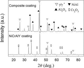
XRD patterns of the as-deposited and as-annealed coatings are presented in Fig. 1. It can be seen that the main phase in the NiCrAlY coating is γ /γ ′ , while β -NiAl phase and α -Cr phase appeared in the as-annealed coating, resulting from the homogenization during the annealing treatment[17]. For the composite coating, the phases detected exist mainly in the outer layer. The as-deposited composite coating is mainly composed of Al phase with the presence of NiAl3 phase and γ /γ ′ phase. After the annealing treatment, the composite coating consists of β -NiAl phase with a small number of γ /γ ′ and α -Cr phases. The two as-annealed coatings show similar phase constituents but different diffraction peak intensities.
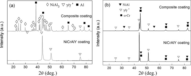 | Fig 1. XRD patterns of the NiCrAlY coating and composite coating (as-deposited (a) and as-annealed (b)). |
Fig. 2 shows the cross-sectional back-scattered electron (BSE) images of the as-deposited and as-annealed coatings. The thickness of the NiCrAlY coating is about 40 m. After the annealing treatment, the coating is homogeneous, with trace dark β phase particles scattering in the lighter γ /γ ′ phase base, which is in accordance with the XRD results. In Fig. 2(b), the thickness of the AlNiY layer is about 12 m, and the total thickness of composite coating is about 52 m. The outer layer of the composite coating is composed of γ /γ ′ phase strips and β phase base. After the annealing treatment, the coatings are dense and adhere well to the substrates.
 | Fig 2. Cross-sectional BSE images of the NiCrAlY coating (a, c) and composite coating (b, d) (as-deposited (a, b) and as-annealed (c, d)). |
The cross-sectional element concentration profiles from the surface to the substrate for the NiCrAlY coating and the composite coating are shown in Fig. 3. For the NiCrAlY coating, Al content is uniform while Cr content is fluctuated because of the different phases being measured. Similar to the MCrAlY coatings deposited by cathodic arc evaporation [18], the Al content in the NiCrAlY coating is lower and Cr content is higher than that of the target material. For the composite coating, the variation of Al content is gradual from the surface to substrate, while Cr is mainly rich in the inner layer. It should be noted that a transition zone exists between the outer layer and the inner layer, where the content of Cr is much higher because of the existence of a plenty of Cr-rich precipitates. It is obvious that the composite coating presents a graded distribution of elements in the Al-rich outer layer and Cr-rich inner layer after the annealing treatment.
 | Fig 3. Element distribution profiles in the cross-section of the NiCrAlY coating (a) and the composite coating (b). |
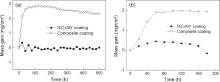
Fig. 4 shows corrosion kinetic curves of the NiCrAlY coating and the composite coating with thin salt films of 75 wt% Na2SO4 + 25 wt% K2SO4 (Fig. 4(a)) and 75 wt% Na2SO4 + 25 wt%NaCl (Fig. 4(b)) at 700 ° C, respectively. The net mass change of the coating specimens composes a mass gain of scale formation and growth, together with a mass loss of scale spallation and dissolution. It can be seen that the mass gain of NiCrAlY coating fluctuates in the initial 100 h in mixed salts of Na2SO4 + K2SO4 and then decreases gradually with time, while the composite coating has a larger mass gain in 60 h and then decreases slowly with time. In the mixed salts of Na2SO4 + NaCl, the mass gain of the NiCrAlY coating increases slowly during the first 60 h and then decreases gradually with time. For the composite coating, the mass gain increases quickly in 60 h and then remains almost constant with increasing time.
 | Fig 4. Corrosion kinetic curves of the coatings in 75 wt% Na2SO4 + 25 wt% K2SO4 (a) and 75 wt% Na2SO4 + 25 wt% NaCl (b) at 700 ° C. |
XRD analysis of the surface corrosion products of the two coatings after corrosion in Na2SO4 + K2SO4 at 700 ° C is presented in Fig. 5. In the whole corrosion process, the scale formed on the surface of NiCrAlY coating is simplex Cr2O3, while the scale formed on the surface of composite coating is only Al2O3.
 | Fig 5. XRD patterns of the coatings after corrosion with 75 wt% Na2SO4 + 25 wt% K2SO4 at 700 ° C (corrosion for 240 h (a) and 500 h (b)). |
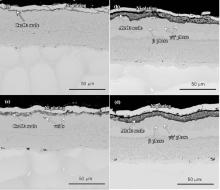
Fig. 6 shows the cross-sectional morphologies of the coatings after corrosion in Na2SO4 + K2SO4 at 700 ° C. As can be seen, the Cr2O3 scale on the NiCrAlY coating is thinner than the Al2O3 scale on the composite coating, in accordance with the corrosion kinetic curves in Fig. 4(a). It should be noted that there is a Cr consumption layer beneath the Cr2O3 scale, which expanded obviously with the corrosion process. Meanwhile, a few oxidation holes were formed in the surface layer of the coating. For the composite coating, the outer layer is still composed of β matrix with γ /γ ′ strips. In addition, it can be seen that a continuous strap shaped zone was formed in the middle of the coating. The EDS results showed that the strap is rich in Cr, which may be owed to the congregation of Cr-rich precipitates in the transition zone (in Fig. 3(b)) during the corrosion process.
 | Fig 6. Cross-sectional BSE images of the NiCrAlY coating (a, c) and the composite coating (b, d) after corrosion in 75 wt% Na2SO4 + 25 wt% K2SO4 at 700 ° C (corrosion for 240 h (a, b) and 500 h (c, d)). |
Fig. 7 shows XRD results of the corrosion products after corrosion in Na2SO4 + NaCl at 700 ° C. Similar to the results in Na2SO4 + K2SO4, the corrosion scale of the NiCrAlY coating is still only Cr2O3 after corrosion for 180 h. For the composite coating, Al2O3 is also identified as the corrosion product during the corrosion, and it can be observed that the diffraction peak of β phase is weaker compared with that in Na2SO4 + K2SO4.
 | Fig 7. XRD patterns of the coatings after corrosion for 180 h in 75 wt% Na2SO4 + 25 wt% NaCl at 700 ° C. |
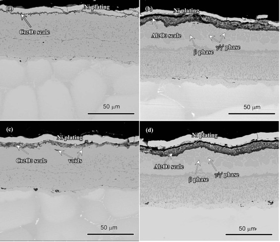
Fig. 8 shows the cross-sectional morphologies of the coatings after corrosion in Na2SO4 + NaCl. The Cr2O3 scale formed on the surface of the NiCrAlY coating is thinner than that of the Al2O3 scale formed on the composite coating. Furthermore, internal oxides and chromium sulfides can be observed in the outer layer of the NiCrAlY coating. It is obvious that the presence of NaCl leads to an accelerated process of the corrosion. For the composite coating, the scale on the surface is continuous, and no internal oxide and chromium sulfide are formed during the corrosion. Beneath the scale, γ /γ ′ is the dominant phase in the outer layer, with only a little β phase left due to the consumption of Al. During the whole corrosion process, the inner layer remained complete and intact. As mentioned above, the composite coating shows better corrosion resistance than the NiCrAlY coating.
 | Fig 8. Cross-sectional BSE images of the NiCrAlY coating (a) and the composite coating (b) after corrosion for 180 h in 75 wt% Na2SO4 + 25 wt% NaCl at 700 ° C. |
Usually, there are two categories of hot corrosion which are distinguished mainly by the temperature ranges when they occur[19]: type I (high temperature, 900 ° C) hot corrosion and type II (low temperature) hot corrosion. For the sulfate salts, type II hot corrosion usually happens at temperatures between 593 and 760 ° C[19, 20], while for the mixed salts containing chloride, type I hot corrosion may take place at 700 ° C, since the temperature is above the melting point of the mixed salts[20]. Therefore, both type I and type II hot corrosions occurred in this study. The protective oxide scale formed on the NiCrAlY coating is Cr2O3, while it is Al2O3 for the composite coating in both types of corrosion.
In the corrosion tests in 75 wt% Na2SO4 + 25 wt% K2SO4 at 700 ° C, the salts are solid, since the melting point of the mixed salts is about 823 ° C[21]. It seems that the corrosion is not serious for the two coatings. However, the corrosion in these corrosion tests should not be neglected. It is generally agreed that corrosion at these low temperatures is made possible by the formation of a Na2SO4-MSO4 (M is typically Ni and/or Co) eutectic which has a melting point (Na2SO4-NiSO4: 671 ° C, and Na2SO4-CoSO4: 565 ° C) well below that of alkali sulfates [19, 22]. The formation of MSO4 can be induced by the sulfation of transient oxides. These eutectics with low melting point would dissolve the beneficial elements and prevent the formation or repairmen of the protective scale, resulting in the aggravation of the corrosion. During the corrosion, although no obvious sulfide and pitting were found inside the coatings, a few internal oxidation holes were formed in the surface layer beneath the scale on the NiCrAlY coating, and the Cr2O3 scale is much thinner than the Al2O3 scale on the composite coating. All these indicate that the NiCrAlY coating performed worse than the composite coating. It could be concluded that the NiCrAlY coating would suffer severe corrosion following the depletion of Cr. For the composite coating, the Al2O3 scale is much thicker and it could be sustained by Al reservoir of the outer layer during the corrosion. Even in the case that Al in this layer is exhausted, the inner layer enriched with Cr could still prevent the corrosion for quite a period of time. Thus the composite coating possesses better corrosion resistance than the NiCrAlY coating in the succedent corrosion.
During the corrosion tests in 75 wt% Na2SO4 + 25 wt% NaCl, the mixed salts were molten as the melting point of the salts is about 620 ° C[20], so that type I hot corrosion happened. The corrosion of the two coatings is more serious compared with that in Na2SO4 + K2SO4. According to the basic fluxing mechanism, the protective oxides (Al2O3 or Cr2O3) can be dissolved in different ways resulting from the basicity (or acidity) of the molten salts[23, 24, 25]. Besides the dissolution, cracking and spallation resulting from the stress also contribute to the deterioration of the oxide scales. Additionally, it should be noted that the presence of NaCl accelerated the cracking or breaking of the oxide scale[25, 26, 27, 28], contributing to the degeneration of the coatings. For the NiCrAlY coating, the Cr2O3 scale formed on the surface dissolves more easily than Al2O3 in sulfate salts[23], and tends to be loosened due to the dissolution and cracking during the corrosion. Then the oxygen and sulfur diffuse through the defects and penetrate into the coating, leading to the formation of internal oxide and chromium sulfide. It would further speed up the corrosion process and promote the failure of the coating. Compared with the NiCrAlY coating, the composite coating shows better corrosion resistance without appearance of internal oxidation and sulfuration in the coating. The main reason can be attributed to its self-healing ability due to the sufficient aluminum in the outer layer.
As mentioned above, the good performance of the composite coating is mainly attributed to the Al-rich outer layer during the two kinds of corrosion process. The Cr-rich inner layer is not attacked and the effect of the Cr-rich inner layer on corrosion is not exhibited yet. This layer is similar to the NiCrAlY coating in compositions; thus it is predictable that the Cr-rich layer can provide similar resistance accordingly during the corrosion. So it is conclusively predictable that the composite coating possesses better corrosion resistance and service life.
A NiCrAlY + AlNiY composite coating was prepared by arc ion plating. After annealing treatment, the composite coating possesses a graded distribution of Al-rich outer layer and Cr-rich inner layer. The outer layer is composed of a β -NiAl matrix with dispersed precipitates of γ /γ ′ phase and α -Cr phase. In Na2SO4 + K2SO4, the two coatings showed good corrosion resistance. The composite coating contained potential corrosion performance due to the sufficient Al reservoirs to supply continuous protective scale. The presence of NaCl aggravated the corrosion extent of the two coatings. Compared with the NiCrAlY coating, the composite coating postponed the formation of internal oxides and sulfides due to the gradient element distribution in the Al-enriched outer layer and the Cr-enriched inner layer.
This work was supported by the National Natural Science Foundation of China (Grant No. 51001106).
| [1] |
|
| [2] |
|
| [3] |
|
| [4] |
|
| [5] |
|
| [6] |
|
| [7] |
|
| [8] |
|
| [9] |
|
| [10] |
|
| [11] |
|
| [12] |
|
| [13] |
|
| [14] |
|
| [15] |
|
| [16] |
|
| [17] |
|
| [18] |
|
| [19] |
|
| [20] |
|
| [21] |
|
| [22] |
|
| [23] |
|
| [24] |
|
| [25] |
|
| [26] |
|
| [27] |
|
| [28] |
|