Oussama El Baradai, Davide Beneventi, Fannie Alloin, Roberta Bongiovanni, Nadege Bruas-Reverdy, Yann Bultel, Didier Chaussy. Microfibrillated Cellulose Based Ink for Eco-Sustainable Screen Printed Flexible Electrodes in Lithium Ion Batteries. Journal of Materials Science & Technology, 2016, 32(6): 566-572
Permissions
Copyright reserved, Editorial board of Journal of Materials Science & Technology
Received:2015-12-03
Microfibrillated Cellulose Based Ink for Eco-Sustainable Screen Printed Flexible Electrodes in Lithium Ion Batteries
Oussama El Baradai1,2,*, Davide Beneventi1,2, Fannie Alloin3,4, Roberta Bongiovanni5, Nadege Bruas-Reverdy1,2, Yann Bultel3,4, Didier Chaussy1,2
1 Univ. Grenoble Alpes, LGP2, F-38000 Grenoble, France
2 CNRS, LGP2, F-38000 Grenoble, France
3 Univ. Grenoble Alpes, LEPMI, F-38000 Grenoble, France
4 CNRS, LEPMI, F-38000 Grenoble, France
5 Department of Applied Science and Technology DISAT, Politecnico di Torino, Corso Duca degli Abruzzi 24, 10129 Torino, Italy
Corresponding author. Ph.D.; Tel.: +33 4 76826954; Fax: +33 4 76826933. (O. El Baradai). E-mail address: Oussama.El-Baradai@lgp2.grenoble-inp.fr (O. El Baradai).
Abstract
Free organic solvent ink containing graphite, carboxymethyl cellulose and microfibrillated cellulose as active material, dispersing and binder, respectively, has been formulated to produce flexible and eco-sustainable electrodes for lithium ion batteries. Content ratio of components and dispersion protocol were tailored in order to have rheological properties suitable for a large and cheap manufacturing process as well as screen printing. The bio-sourced printed electrodes exhibit a high porosity value of 70% that limits the electrochemical performances. However, the calendering process enhances electrode performances by increasing the reversible capacity from 85 until 315 mAh/g and reducing porosity to an optimal value of 34%. Moreover the introduction of 2% w/w of monofluoro-ethylene carbonate in the electrolyte reduced their reversible capacity loss of 11% in the printed electrode.
Lithium-ion batteries (LIBs) represent nowadays the best solution in terms of energy density, i.e. 150 Wh kg-1 and 650 Wh l-1[1]. Different materials have been studied and employed in LIBs[2, 3], nevertheless the necessity of environmental friendly and eco-sustainable processes leads to the development of electrodes with tailored properties in order to respect the aforementioned requirements[4]. One viable route to the development of “ green” manufacturing process is the introduction of water processable bio-sourced materials, such as cellulose and its derivatives[5]. Jabbour et al. developed self-standing and easily recyclable lithium iron phosphate based (LFP) positive electrode by using cellulose fibers as bio-sourced binder[6]. The obtained electrode showed Young's modulus higher than 100 MPa and a discharge capacity values up to 110 mAh/g. Mechanical and electrochemical results were comparable with classical polymer binder LiFePO4 based electrode. Moreover, using the same manufacturing technique and the same materials (LiFePO4, nano-fibrillated cellulose), Leijonmarck et al.[7] developed a flexible paper based positive electrode. The resulting cell exhibits an appreciable stress at break, i.e. 2.2 MPa even when soaked with electrolyte and a reversible capacity of 151 mAh/g at C/10 was obtained. Recently, in addition to the environmental point of view, the aspect of flexibility drove the LIBs market leading to the rapid development of lightweight, thin, flexible and small units[8]. This bias responds to the necessity of power sources adaptable in emerging fields as wearing[9] and roll-up electronic devices[10]. One possible solution was proposed by Beneventi et al.[11] by developing a large-scale production system for self-standing thin graphite negative electrodes, based on spray coating technology and cellulose binder. The manufactured electrodes presented a reversible capacity of 350 mAh/g at C/10 comparable with standard compositions. In parallel, printed processes have been investigated as alternative technique to fulfill the requirement of flexibility and to reduce manufacturing cost. Many researchers explored the potential of printing techniques in order to develop functional electronic devices and structures[12, 13, 14]. Results are promising, but the spread of these technologies has been limited by some crucial factors such as not safe components[15] or not viable large scale applications[16]. At present the requirement of eco-sustainability leads to the development of water based inks, replacing organic based solvents, for printing processes. In fact a water based ink offers different advantages, such as reduced volatility and lower reactivity[17, 18]. One example of water based screen printing inks for electronic applications was reported by Hashimoto et al.[19]. They developed printed fuel cell based on water solvent, to avoid environmental pollution due to the higher reactivity of classic organic based solvent. Faddoul et al.[20] formulated and screen printed water based silver pastes by obtaining electrical conductivities comparable with commercial paste for electronic applications. Nevertheless the definitive transition to aqueous based printing processes encountered nowadays some difficulties related to the ink formulation, viscosity control and film processing, which must be overcome for successful developing in LIBs. The properties of printed films strongly depend on the viscosity and the composition of the ink. Lee et al.[21] reported how the mixing process influences the performances of LiCoO2 based electrodes. In fact, at fixed solid loading, the mixing process changes dramatically the rheological properties. The ink formulated by a multistep process exhibits lower viscosity, thus the solid components are uniformly dispersed. As a result the conductive agent particles are more uniformly distributed and the electrode polarization is reduced.
To the best of our knowledge, no previous researches have been reported on the use of cellulose derivatives and water based inks for the elaboration of lithium ion batteries by means of a printing process. To this effect, the aim of this work is to demonstrate the feasibility of eco-sustainable flexible, negative electrodes for LIBs by using a low cost manufacturing process as well as screen printing, and by developing a new formulation ink consisting in water based solvent and microfibrillated cellulose compounds as binder. The rheological properties were tailored and optimized to the printing process, and physical and electrochemical characterizations of the electrodes were carried out.
2. Experimental
2.1. Materials
Graphite particles with potato shape (GP) battery grade purchased by Timcal, with a measured mean diameter of 9 m and a nominal specific surface area of 10.0 m2/g, were used as active material for the fabrication of negative electrode. Carboxymethylcellulose (CMC) with an average molecular weight of 90, 000 g mol-1 and degree of substitution 0.7 was purchased from Aldrich. Microfibrillated cellulose (MFC) derived from bleached Domsjö pulp were purchased from “ Institute Technologique Foret Cellulose Bois-construction Ameublement” (FCBA). The liquid electrolyte (battery grade) composed of 1 mol/L Hexafluorophosphate (LiPF6) in a 1:1:3 volume mixture of ethylene carbonate (EC), propylene carbonate (PC) and dimethyl carbonate (DMC) was provided by Purolyte. A lithium foil purchased by Alpha Aesar was used as counter electrode. Celgard 2500 was selected as separator. Mono-fluoroethylene carbonate (1FEC) was supplied by Aldrich. The cellulosic based separator was provided by Papyrus. Physical characteristics of the cellulose based separator are listed in Table 1.
Table 1
Table 1
Table 1 Physical characteristics of the cellulosic based separator
Thickness (m)
Loading (g/m2)
Porosity (%)
Air permeability (cm3/cm2 min-1)
142 ± 2
120
47
417
Table 1 Physical characteristics of the cellulosic based separator
2.2. Rheological characterization
The rheological properties of the inks were measured using a plate-plate rheometer Anton Paar. Measurements were performed at 25 ° C at a fixed gap of 1 mm. The samples were equilibrated 1 min to remove any previous shear history. Steady state flow measurements were made from 10-1 to 103 s-1 to determine the ink viscosity. For the dynamic viscoelastic measurements, the linear viscoelastic range was determined with a stress sweep ranging from 1 to 104 Pa at a fixed frequency of 2 Hz. A frequency sweep was performed by applying a constant shear stress of 1 Pa over a frequency range from 0.1 to 100 rad/s.
2.3. Ink formulation
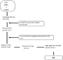
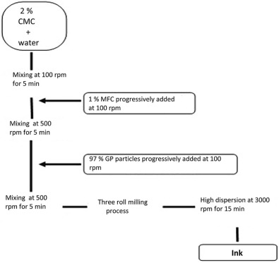
The ink containing 40% w/w of dry solid content composed of 97% w/w of graphite, 1% w/w of MFC and 2% w/w of CMC was formulated by following the formulation process depicted in Fig. 1.
2.4. Printing and physical characterization of electrodes
Screen printing tests were performed with a DEK Horizon 03i screen printing press. A polyamide nylon screen mesh (208 threads per inch, 40% open area, 70 m thread diameter and 110 m emulsion thickness) was used to achieve printing tests. A polymer squeegee forming an angle of 60° with the screen and having 70-75 shore hardness was used. The printing speed was fixed at 110 mm/s and the printing force at 50 N. Off contact between the substrate and the mesh was fixed at 1 mm. An area (4 cm × 25 cm) was printed onto the cellulosic based substrate and dried by heating at 105 ° C for 10 min then at ambient temperature for 24 h.
Electrode thickness was measured using a mechanical gauge (Adamel Lhomargy) according to the ISO 534. A quanta 200 FEI environmental scanning microscope (ESEM) was used to perform surface micrographs. Cross section and part of surface images were realized by means of a Zeiss ultra 55 FESEM. The conductivity of the electrodes was measured using a four probes ohmmeter (Jandel, Universal Probe).
The porosity was estimated by considering the void and bulk volume of the electrodes. Roughness measurements of the electrodes were carried out with an ALICONA Infinite Focus optic microscope.
A laboratory calendering machine was used to tailor the porosity of the electrodes by applying a varying linear load to reduce the thickness of the electrodes.
2.5. Electrochemical characterization
Disks of 0.8 cm of diameter were punched out of the printed electrode and dried at 105 ° C under vacuum over one night to insure the total removal of water. The electrochemical behavior of the electrodes was tested in a Teflon® made two electrode cell. A lithium foil was used as counter electrode. The galvanostatic cycling tests were performed at ambient temperature using an Arbin Instrument model S/N 170795. The cells were assembled in argon-filled Iacomex glove box with oxygen and water content less than 30 ppm. Linear voltammetry experiments were carried out with a Teflon® made three electrodes at ambient temperature with a scan rate of 0.01 mV/s. A lithium foil was used as reference and counter electrodes. Ionic conductivity measurements were performed in Teflon® made two electrodes, assembled in glove box. Blocking electrodes were made by 1 cm diameter stainless steel. Ionic conductivity measurements were performed by means of impedance spectroscopy over the frequency range 100 kHz-10 mHz with ± 10 mV amplitude using a Biologic analyzer equipped with an EC-LAB interface.
3. Results and Discussion
3.1. Formulation and rheological characterization of the inks
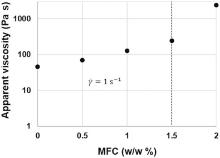
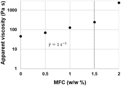
Fig. 2 shows the evolution of the apparent viscosity as function of MFC content at a fixed solid content of 40% w/w. A critical concentration is observed at 1.5% w/w. Up to this value, the apparent viscosity grows rapidly. This behavior is in agreement with the rheological properties of MFC aqueous suspensions reported in literature that reveals the existence of a critical concentration above which the mechanical entanglement of the fiber creates a fiber network[22]. The influence of CMC is observed in the thinning behavior reported for the ink (Fig. 3). As for polymer coils in solution, the disentanglement of CMC chains lead to a wrapping of the graphite particles that reduces the friction between them. Indeed Ueno et al.[23] observed a uniform net when CMC is deposed onto graphite particles. As a result, a decrement of viscosity of about one order of magnitude, at a fixed shear rate, was obtained when CMC was added to a graphite aqueous suspension.
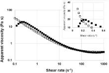
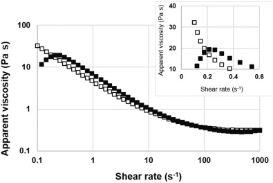
Fig 3. Apparent viscosity as function of shear rate for increasing (■) and decreasing (□) shear rate. The inset shows the existence of a yield stress.
3.1.1. Flow state measurements
Fig. 3 shows the evolution of apparent viscosity as function of shear rate. The first step consists in measuring apparent viscosity from 10-1 to 103 s-1 as shown by filled squares curve. A decrease of the apparent viscosity as function of shear rate, typical of shear thinning suspensions[24], has been measured (filled squares curve). The same experiment was performed by varying the shear rate from 103 to 10-1 s-1 (empty squares curve). A mismatch between the two curves was observed at low shear rates (< 10 s-1), pointed out by the dotted bordering zone in the graph. A hysteresis, related to the thixotropy of the ink, is then observed. As described by Barnes[25], Non-Newtonian thixotropy is the ability of a suspension to recover its gel structure. Ghannam and Esmail[26] described how CMC has the ability to recover the structure of an ink when it is allowed to rest for a long period time, after attaining complete breakdown. The same ability was reported for MFC aqueous solutions by Iotti et al.[27]; moreover the MFC based suspensions exhibit a time dependent behavior with the formation of a hysteresis loop. This behavior was observed in our analysis, as shown in Fig. 3. At low shear rate (≤ 0.2 s-1) the ink exhibits an increase of the viscosity until a maximum point (inset in Fig. 3). The existence of a critical shear rate suggests that the ink has cohesive properties corresponding to a yield stress at which ink begins to flow. Measured viscosity values at low shear rates are conformed with screen printing process viscosity requirements ranging between 10 and 150 Pa s[28].
3.1.2. Oscillatory measurements
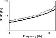
The viscoelastic properties of the ink are described in Fig. 4. The figure shows how the ink exhibits frequency dependent viscoelastic moduli. A progressive increase of both moduli has been obtained in the range of frequencies. Moreover the storage modulus (G′ ) is always higher than loss modulus (G″) within the frequency range. This is an evidence of a structured paste where the solid like behavior is predominant. MFC binding properties may be at the origin of this behavior. Rheological studies of MFC suspensions show how MFCs have a gel like behavior in a large range of frequency with G′ > G″ [29, 30].
Fig 4. Storage (G′ ; □) and loss (G″; ■) modulus as function of frequency.
3.1.3. Influence of printing process on rheological properties
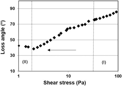
In order to study the behavior of the ink during the printing process, a rheological analysis was performed by simulating different stages of printing process. Analogue investigations were reported by Neidert et al.[31] for silver based pastes. They simulated the rheological behavior of a paste prior, during and after screen printed process. For our purpose, we performed oscillatory measurements to simulate the ink behavior at higher shear stresses, corresponding to the passage of the ink through the screen (I) and during low shear stresses, to simulate the transfer from the screen to the substrate (II). Fig. 5 shows the loss angle (δ ) as function of shear stress. A δ close to 0° indicates solid like behavior while a δ close to 90° indicates a liquid like behavior. The transition from a solid to a liquid like behavior is observed at δ = 45° . As expected, the passage of the ink through the screen (I) is characterized by a liquid like behavior with δ close to 90° . Conversely, during the transfer from the screen to the substrate, the ink exhibits a loss angle close to 45° . This is coherent with a weak solid behavior during step (II) that maximizes the transfer of the ink and insures a good dispersion of the particles during printing process.
Fig 5. Loss angle as function of shear stress during printing process: (I) represents the passage through the screen while (II) represents the transfer of ink from the screen to the substrate.
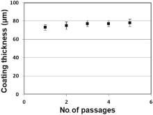
A study of the coating thickness with respect to the number of squeegee passages was realized (Fig. 6). The coating thickness does not seem to be affected by the number of passages. A maximal ink transfer was reached at the first passage. This fact is in agreement with the results shown previously for the loss angle measurements, where a liquid like behavior (maximal ink deposition) was measured during the transfer of the ink from the screen to the substrate. As described by Krebs the coating thickness of the printed layer is related to theoretical volume of the screen fined as the volume between the threads of the screen and the thickness of the emulsion[32]. In our case the theoretical volume is attained after 1 passage of the squeegee. For this reason the coating thickness does not significantly vary after 1 passage.
Fig 6. Coating thickness as function of squeegee passages.
3.2. Physical characterization of the electrodes
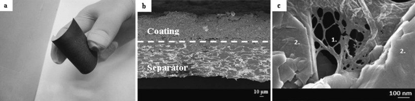
As shown in Fig. 7(a), the nature of the substrate allows manufacturing flexible electrodes. Cross section and topography images were taken by SEM. In Fig. 7(b), two distinct layers are visible: the bottom corresponds to the cellulosic substrate and the top to the negative electrode layer. During the coating of the ink, no particle goes through the macroporous separator. Indeed, the graphite particles have a mean diameter of 9 m. This value is significantly higher than the average surface pore size of the separator, generally ranging between 60 nm and 150 nm[33]. As shown in Fig. 7(c), MFCs create a network structure between graphite particles that enhances mechanical properties as described by Jabbour et al.[34].
Fig 7. (a) Image illustrating the flexibility of the printed electrode, (b) cross section image taken by SEM of the electrode at 300 X showing the interface between the negative electrode and the separator, (c) FESEM image at 3 kV showing binding role of MFC particles with network structure between MFC particles marked by 1 and graphite particles marked by 2.
The physical characterization of the negative electrode is shown in Table 2. The thickness of the coating is 71 ± 3 m. This thickness is in good accordance with the one reported by Geyer et al.[35] for a graphite based screen printed electrodes. Because of the cellulosic nature of the substrate, a low content of MFCs (2% w/w) is required to insure cohesion between particles and then an appreciable electrical conductivity (69 S/m) can be obtained, even higher than self-sustainable flexible electrodes reported in the literature. In fact, MFC/graphite based electrodes obtained by filtration technique exhibit lower conductivity (30 S/m) owing to the higher content of MFC (10% w/w)[34]. Calculated porosity of 70% (Table 2) is comparable with results obtained for cast graphite based electrodes containing 90% w/w of graphite particles[36].
Table 2
Table 2
Table 2 Electrode characterization in terms of coating layer, electronic conductivity, density and porosity
Coating thickness (m)
Electrical conductivity (S/m)
Density (g/cm3)
Porosity (%)
71 ± 3
69 ± 19
0.6 ± 0.1
70 ± 3
Table 2 Electrode characterization in terms of coating layer, electronic conductivity, density and porosity
3.3. Electrochemical characterization
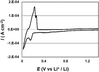
The cyclic voltammogram of screen printed electrodes is shown in Fig. 8. As reported for graphite based electrodes irreversible peaks corresponding to the solid electrolyte interphase (SEI) formation was observed at 0.43 V vs Li+/Li, and reduction peaks associated with the Li+ intercalation process were obtained at 0.15 V and 0.02 V vs Li+/Li. Moreover oxidation peaks have been observed at 0.23 V and 0.24 V vs Li+/Li as generally reported in the literature[37].
Fig 8. Voltammogram at 0.01 mV s-1 for graphite based electrode.
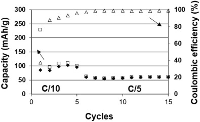
The galvanostatic cycling test is shown in Fig. 9. A capacity of about 100 mAh/g for the first five cycles was measured at C/10, far from the theoretical value of graphite (372 mAh/g), with an initial coulombic efficiency of about 37%. This behavior may be associated with the high porosity of the screen printed electrodes (70%), compared to the conventionally manufactured electrodes, after calendering (30%)[38]. In fact, a too high porosity induces a poor electronic conductivity due to the non-efficient electronic pathway. Furthermore, an electronic disconnection of some graphite particles might occur. As a result, only a part of the active material is involved in charge-discharge reactions. This fact could explain the low reversible capacity obtained. An irreversible capacity loss (ICL) of 143 mAh/g was measured at the first cycle. If we consider the ICL normalized by the specific surface of graphite particles, we obtained 14.3 mAh/m2. This value is higher compared to the data reported by Lamantia et al. ranging between 3 and 10 mAh/m2[39] for a set of synthetic and natural graphites having different size and specific surface characteristics.
Fig 9. Charge (□)/discharge (♦ ) specific capacities and coulombic efficiency (Δ ) as function of cycles at C/10 and C/5.
The cellulosic nature of the separator is not a factor that can affect the electrochemical performance of the cell[40]. The ionic conductivity of the separator swelled by the electrolyte is 3 mS/cm at room temperature, a value lower than results reported for cellulosic based separators, having an ionic conductivity in LiBF4 electrolyte at room temperature ranging between 0.7 and 1.2 mS/cm[41]. This difference in value might be related to the different electrolyte used in this work and to the tortuosity of the separators.
3.4. Calendering study
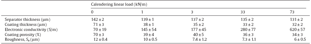
A calendering step was performed to enhance electrochemical properties by increasing electrode's density, which permits to optimize the ionic and electronic conductive pathways. Electrodes were fed through the gap of a calendering machine in order to be compressed at four different loads: 1, 3, 33 and 73 kN/m[42]. The thickness of the printed coated layer was measured as difference between the total thickness of the sample (electrode plus separator) and the thickness of the separator. For this reason, the thickness of the separator was measured as a function of the calendering loads. A maximum variation of 8% of the thickness was observed when the separator was calendered. In fact, during the manufacturing process of cellulose separator, a calendering step is already performed to provide the final structure of the separator by reducing its thickness[28]. Therefore further compression entails just mechanical stress between cellulose fibers without appreciable consequences on the thickness. The porosity varies from 47% to 41% when the separator is calendered at 73 kN/m which may weakly decrease the ionic conductivity of the separator, 2 mS/cm instead of 3 mS/cm. Concerning the coated layer, the main evolution, in terms of thickness and porosity of the coating layer, was observed when the pressure of 1 kN/m was applied (Table 3). Beyond this value, the evolution is much more limited. This behavior is in accordance with the study of Sheng et al. where a rapid decrease of the macroporosity was reported at low calendering pressure for graphite based electrodes[43]. A progressive reduction of the electrode roughness and increase of its electrical conductivity, due to graphite particles contact improvement, are obtained when calendering pressure increases. Electric property and electrode density are not well-connected, as even in the range of pressure where porosity is more or less constant, a neat increase of electric conductivity is observed. This behavior is in agreement with results reported by Wang et al.[44] where an increase of electrical conductivity is observed even when the porosity and the electrode thickness are almost constant. Moreover, Gnanaraj et al.[45] showed how the calendering process affects the morphology of the electrode by reducing the roughness by a factor 24% and forcing graphite particles to be oriented with basal plan parallel to the current collector by improving uniformity and thus electrical contacts.
Table 3
Table 3
Table 3 Electrode characterization in terms of coating layer, electronic conductivity, density, porosity and surface roughness
Table 3 Electrode characterization in terms of coating layer, electronic conductivity, density, porosity and surface roughness
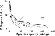
An increase of the specific capacity (Fig. 10) has been obtained when the calendering pressure increases. The electrode densification enhances electrical and ionic pathways and limits the cell polarization. The polarization of the cell has a large impact on the capacity value due to the cut of voltage fixed at 0 V vs Li/Li+ to prevent metallic lithium deposition. Indeed the best results have been obtained for a calendering linear load of 73 kN/m, corresponding to a porosity of 34% and an electronic conductivity of 620 S/m, with an average capacity of 315 mAh/g at C/10.
Fig 10. Discharge profile at C/10 as function of calendering pressure at 0, 1, 3, 33 and 73 kN/m. Each curve represents the discharge capacity at the second discharge cycle.
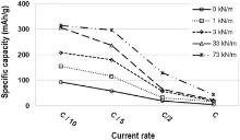
In Fig. 11, specific capacity at different calendering loads is reported as function of C-rates ranging between C/10 and C. For a given calendering load, the capacities obtained at C/10 and C/5 are similar, and a neat decrease of the performances was observed from C/2. The decrease in the specific capacity observed when increasing C-rates can be ascribed to the limitation in lithium ion diffusion through the electrode[46, 47].
Fig 11. Specific capacity as function of current rates at different calendering linear loads.
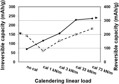
The reversible and irreversible capacities are plotted against calendering load at C/10 (Fig. 12). Concerning the irreversible capacity, a reduction was observed at 1 kN/m, followed by a progressive increment when calendering load increases.
Fig 12. Irreversible (□) and reversible (♦ ) capacity at the 1st cycle during SEI formation as function of calendering linear load.
A strategy to limit the irreversible capacity is the addition of an additive in the electrolyte formulation that can promote the formation of a stable passive layer[48]. For this reason, a preliminary test was performed by adding 2% w/w of mono-fluoroethylene carbonate (1FEC) to the electrolyte formulation. A decrease of the irreversible capacity of 11% with respect to the ternary electrolyte without additive was observed. At the same time, an increment of the reversible capacity was measured attaining a value of 268 mAh/g when the additive is added to the electrolyte.
4. Conclusions
This study demonstrated how bio-sourced components as microfibrillated cellulose (MFC) coupled with water based solvent could be a “ green chemistry” viable route to formulate inks with suitable properties for the manufacturing of negative electrodes for LIBs. Indeed the utilization of a large area and cheap process such as screen printing allows the fabrication of flexible electrodes.
Rheological results demonstrated the feasibility of bio-sourced electronic ink with suitable rheological properties in terms of apparent viscosity and viscoelastic moduli adapted for a large scale process as screen printed. Moreover electrochemical results revealed the negative impact of the elevated porosity (70%) on the performance of the electrode. Nevertheless, thanks to the calendering process, the performance can be considerably enhanced allowing the densification of the electrode and the increment of the reversible capacity from a value of 93 mAh/g to 315 mAh/g. However calendering process and electrolyte formulation have to be tailored in order to control the irreversible capacity loss during SEI formation.
AcknowledgementsAcknowledgments
This work was partially supported by the Énergies du Futur Carnot Institute (Investissements d'Avenir—grant agreement No. ANR-11-CARN-030-01). The authors acknowledge the facilities of the TekLiCell platform funded by the Région Rhône-Alpes (ERDF: European Regional Development Fund).
J. M. Tarascon, M. Armand , Nature, 414(2001), pp. 359-367[本文引用:1]
[2]
R. Yazami, J. Power Sources, 97(2001), pp. 33-38[本文引用:1]
[3]
T. Ohzuku, R. J. Brodd, J. Power Sources, 174(2007), pp. 449-456[本文引用:1]
[4]
D. L. Wood, J. Li, C. Daniel, J. Power Sources, 275(2015), pp. 234-242[本文引用:1]
[5]
L. Jabbour, R. Bongiovanni, D. Chaussy, C. Gerbaldi, D. Beneventi, Cellulose, 20(2013), pp. 1523-1545[本文引用:1]
[6]
L. Jabbour, M. Destro, D. Chaussy, C. Gerbaldi, N. Penazzi, S. Bodoardo, D. Beneventi, Cellulose, 20(2013), pp. 571-582[本文引用:1]
[7]
S. Leijonmarck, A. Cornell, G. Lindbergh, L. Wågberg, J. Mater. Chem. A. , 1(2013), p. 4671[本文引用:1]
[8]
G. Zhou, F. Li, H. M. Cheng, Energy Environ. Sci, 7(2014), pp. 1307-1338[本文引用:1]
[9]
Y. Liu, S. Gorgutsa, C. Santato, M. Skorobogatiy, J. Electrochem. Soc, 159(2012), pp. A349-A356[本文引用:1]
[10]
A. Vlad, A. L. M. Reddy, A. Ajayan, N. Singh, J. F. Gohy, S. Melinte, P. M. Ajayan, Proc. Natl. Acad. Sci, 109(2012), pp. 15168-15173[本文引用:1]
[11]
D. Beneventi, D. Chaussy, D. Curtil, L. Zolin, E. Bruno, R. Bongiovanni, M. Destro, C. Gerbaldi, N. Penazzi, S. Tapin-Lingua, Chem. Eng. J. , 243(2014), pp. 372-379[本文引用:1]
[12]
M. Granmar, A. Cho, Science, 308(2005), pp. 785-786[本文引用:1]
[13]
H. Sirringhaus, T. Shimoda, MRS Bull, 28(2003), pp. 802-806[本文引用:1]
[14]
S. -H. Kim, K. -H. Choi, S. -J. Cho, S. Choi, S. Park, S. -Y. Lee, Nano Lett, 15(2015), pp. 5168-5177[本文引用:1]
[15]
M. S. Park, S. H. Hyun, S. C. Nam, J. Power Sources, 159(2006), pp. 1416-1421[本文引用:1]
[16]
K. Sun, T. -S. Wei, B. Y. Ahn, J. Y. Seo, S. J. Dillon, J. A. Lewis, Adv. Mater, 25(2013), pp. 4539-4543[本文引用:1]
[17]
K. S. Howe, E. R. Clark, J. Bowen, K. Kendall, Int. J. Hydrog. Energy, 38(2013), pp. 1731-1736[本文引用:1]
[18]
C. -C. Li, J. -T. Lee, X. -W. Peng, J. Electrochem. Soc, 153(2006), p. A809[本文引用:1]
[19]
N. Hashimoto, S. Niijima, J. Inagaki, J. Eur. Ceram. Soc, 29(2009), pp. 3039-3043[本文引用:1]
[20]
R. Faddoul, N. Reverdy-Bruas, A. Blayo, Mater. Sci. Eng. B. , 177(2012), pp. 1053-1066[本文引用:1]
[21]
G. -W. Lee, J. H. Ryu, W. Han, K. H. Ahn, S. M. Oh, J. Power Sources, 195(2010), pp. 6049-6054[本文引用:1]
[22]
M. -P. Lowys, J. Desbrieres, M. Rinaudo, Food Hydrocoll, 15(2001), pp. 25-32[本文引用:1]
[23]
T. Ueno, S. Yokota, T. Kitaoka, H. Wariishi, Carbohydr. Res, 342(2007), pp. 954-960[本文引用:1]
[24]
D. J. Jeffrey, A. Acrivos, AIChE J. , 22(1976), pp. 417-432[本文引用:1]
[25]
H. A. Barnes, J. Non-Newton, Fluid Mech, 70(1997), pp. 1-33[本文引用:1]
[26]
M. T. Ghannam, M. N. Esmail, J. Appl. Polym. Sci, 64(1997), pp. 289-301[本文引用:1]
[27]
M. Iotti, Ø. W. Gregersen, S. Moe, M. Lenes, J. Polym. Environ, 19(2011), pp. 137-145[本文引用:1]
[28]
H. Kipphan (Ed. ), Hand book of Print Media: Technologies and Production Methods, SpringerBerlin; NewYork (2001)[本文引用:2]
[29]
A. -H. Vesterinen, P. Myllytie, J. Laine, J. Seppälä, J. Appl. Polym. Sci(2010), pp. 2990-2997[本文引用:1]
[30]
G. Agoda-Tand jawa, S. Durand , S. Berot, C. Blassel, C. Gaillard, C. Garnier, J. -L. Doublier, Carbohydr. Polym, 80(2010), pp. 677-686[本文引用:1]
[31]
M. Neidert, W. Zhang, D. Zhang, A. Kipka, Photovolt. Spec. Conf. 2008 PVSC08 33rd IEEE, in; IEEE(2008), pp. 1-4[本文引用:1]
N. Loeffler, J. von Zamory, N. Laszczynski, I. Doberdo, G. -T. Kim, S. Passerini, J. Power Sources, 248(2014), pp. 915-922[本文引用:1]
[43]
Y. Sheng, C. R. Fell, Y. K. Son, B. M. Metz, J. Jiang, B. C. Church, Front. Energy Res, 2(2014), p. 56[本文引用:1]
[44]
C. -W. Wang, Y. -B. Yi, A. M. Sastry, J. Shim, K. A. Striebel, J. Electrochem. Soc, 151(2004), p. A1489[本文引用:1]
[45]
J. S. Gnanaraj, Y. S. Cohen, M. D. Levi, D. Aurbach, J. Electroanal. Chem, 516(2001), pp. 89-102[本文引用:1]
[46]
M. -S. Park, S. -H. Hyun, S. -C. Nam, Electrochim. Acta, 52(2007), pp. 7895-7902[本文引用:1]
[47]
J. Lee, C. Jo, B. Park, W. Hwang, H. I. Lee, S. Yoon, J. Lee, Nanoscale, 6(2014), pp. 10147-10155[本文引用:1]
[48]
M. C. Smart, B. L. Lucht, S. Dalavi, F. C. Krause, B. V. Ratnakumar, J. Electrochem. Soc, 159(2012), pp. A739-A751[本文引用:1]
1
2001
0.0
0.0
... 150 Wh kg-1 and 650 Wh l-1[1] ...
1
2001
0.0
0.0
... Different materials have been studied and employed in LIBs[2,3], nevertheless the necessity of environmental friendly and eco-sustainable processes leads to the development of electrodes with tailored properties in order to respect the aforementioned requirements[4] ...
1
2007
0.0
0.0
... Different materials have been studied and employed in LIBs[2,3], nevertheless the necessity of environmental friendly and eco-sustainable processes leads to the development of electrodes with tailored properties in order to respect the aforementioned requirements[4] ...
1
2015
0.0
0.0
... Different materials have been studied and employed in LIBs[2,3], nevertheless the necessity of environmental friendly and eco-sustainable processes leads to the development of electrodes with tailored properties in order to respect the aforementioned requirements[4] ...
1
2013
0.0
0.0
... manufacturing process is the introduction of water processable bio-sourced materials, such as cellulose and its derivatives[5] ...
1
2013
0.0
0.0
... developed self-standing and easily recyclable lithium iron phosphate based (LFP) positive electrode by using cellulose fibers as bio-sourced binder[6] ...
1
2013
0.0
0.0
... [7] developed a flexible paper based positive electrode ...
1
2014
0.0
0.0
... Recently, in addition to the environmental point of view, the aspect of flexibility drove the LIBs market leading to the rapid development of lightweight, thin, flexible and small units[8] ...
1
2012
0.0
0.0
... This bias responds to the necessity of power sources adaptable in emerging fields as wearing[9] and roll-up electronic devices[10] ...
1
2012
0.0
0.0
... This bias responds to the necessity of power sources adaptable in emerging fields as wearing[9] and roll-up electronic devices[10] ...
1
2014
0.0
0.0
... [11] by developing a large-scale production system for self-standing thin graphite negative electrodes, based on spray coating technology and cellulose binder ...
1
2005
0.0
0.0
... Many researchers explored the potential of printing techniques in order to develop functional electronic devices and structures[12,13,14] ...
1
2003
0.0
0.0
... Many researchers explored the potential of printing techniques in order to develop functional electronic devices and structures[12,13,14] ...
1
2015
0.0
0.0
... Many researchers explored the potential of printing techniques in order to develop functional electronic devices and structures[12,13,14] ...
1
2006
0.0
0.0
... Results are promising, but the spread of these technologies has been limited by some crucial factors such as not safe components[15] or not viable large scale applications[16] ...
1
2013
0.0
0.0
... Results are promising, but the spread of these technologies has been limited by some crucial factors such as not safe components[15] or not viable large scale applications[16] ...
1
2013
0.0
0.0
... In fact a water based ink offers different advantages, such as reduced volatility and lower reactivity[17,18] ...
1
2006
0.0
0.0
... In fact a water based ink offers different advantages, such as reduced volatility and lower reactivity[17,18] ...
1
2009
0.0
0.0
... [19] ...
1
2012
0.0
0.0
... [20] formulated and screen printed water based silver pastes by obtaining electrical conductivities comparable with commercial paste for electronic applications ...
1
2010
0.0
0.0
... [21] reported how the mixing process influences the performances of LiCoO2 based electrodes ...
1
2001
0.0
0.0
... This behavior is in agreement with the rheological properties of MFC aqueous suspensions reported in literature that reveals the existence of a critical concentration above which the mechanical entanglement of the fiber creates a fiber network[22] ...
1
2007
0.0
0.0
... [23] observed a uniform net when CMC is deposed onto graphite particles ...
1
1976
0.0
0.0
... A decrease of the apparent viscosity as function of shear rate, typical of shear thinning suspensions[24], has been measured (filled squares curve) ...
1
1997
0.0
0.0
... As described by Barnes[25], Non-Newtonian thixotropy is the ability of a suspension to recover its gel structure ...
1
1997
0.0
0.0
... Ghannam and Esmail[26] described how CMC has the ability to recover the structure of an ink when it is allowed to rest for a long period time, after attaining complete breakdown ...
1
2011
0.0
0.0
... [27] ...
2
2001
0.0
0.0
... Measured viscosity values at low shear rates are conformed with screen printing process viscosity requirements ranging between 10 and 150 Pa s[28] ...
... In fact, during the manufacturing process of cellulose separator, a calendering step is already performed to provide the final structure of the separator by reducing its thickness[28] ...
1
2010
0.0
0.0
... G″ [29,30] ...
1
2010
0.0
0.0
... G″ [29,30] ...
1
2008
0.0
0.0
... [31] for silver based pastes ...
1
2009
0.0
0.0
... As described by Krebs the coating thickness of the printed layer is related to theoretical volume of the screen fined as the volume between the threads of the screen and the thickness of the emulsion[32] ...
1
2003
0.0
0.0
... This value is significantly higher than the average surface pore size of the separator, generally ranging between 60 nm and 150 nm[33] ...
2
2010
0.0
0.0
... [34] ...
... In fact, MFC/graphite based electrodes obtained by filtration technique exhibit lower conductivity (30 S/m) owing to the higher content of MFC (10% w/w)[34] ...
1
2009
0.0
0.0
... [35] for a graphite based screen printed electrodes ...
1
2004
0.0
0.0
... Calculated porosity of 70% (Table 2) is comparable with results obtained for cast graphite based electrodes containing 90% w/w of graphite particles[36] ...
1
1997
0.0
0.0
... 24 V vs Li+/Li as generally reported in the literature[37] ...
1
1995
0.0
0.0
... This behavior may be associated with the high porosity of the screen printed electrodes (70%), compared to the conventionally manufactured electrodes, after calendering (30%)[38] ...
1
2008
0.0
0.0
... ranging between 3 and 10 mAh/m2[39] for a set of synthetic and natural graphites having different size and specific surface characteristics ...
1
2010
0.0
0.0
... The cellulosic nature of the separator is not a factor that can affect the electrochemical performance of the cell[40] ...
1
1996
0.0
0.0
... 2 mS/cm[41] ...
1
2014
0.0
0.0
... Electrodes were fed through the gap of a calendering machine in order to be compressed at four different loads: 1, 3, 33 and 73 kN/m[42] ...
1
2014
0.0
0.0
... where a rapid decrease of the macroporosity was reported at low calendering pressure for graphite based electrodes[43] ...
1
2004
0.0
0.0
... [44] where an increase of electrical conductivity is observed even when the porosity and the electrode thickness are almost constant ...
1
2001
0.0
0.0
... [45] showed how the calendering process affects the morphology of the electrode by reducing the roughness by a factor 24% and forcing graphite particles to be oriented with basal plan parallel to the current collector by improving uniformity and thus electrical contacts ...
1
2007
0.0
0.0
... The decrease in the specific capacity observed when increasing C-rates can be ascribed to the limitation in lithium ion diffusion through the electrode[46,47] ...
1
2014
0.0
0.0
... The decrease in the specific capacity observed when increasing C-rates can be ascribed to the limitation in lithium ion diffusion through the electrode[46,47] ...
1
2012
0.0
0.0
... A strategy to limit the irreversible capacity is the addition of an additive in the electrolyte formulation that can promote the formation of a stable passive layer[48] ...
Microfibrillated Cellulose Based Ink for Eco-Sustainable Screen Printed Flexible Electrodes in Lithium Ion Batteries
[Oussama El Baradai1,2,*, Davide Beneventi1,2, Fannie Alloin3,4, Roberta Bongiovanni5, Nadege Bruas-Reverdy1,2, Yann Bultel3,4, Didier Chaussy1,2]


 , Davide Beneventi