

Influence of Process Parameters and Sr Addition on the Microstructure and Casting Defects of LPDC A356 Alloy for Engine Blocks
[Giulio Timelli*  , Daniele Caliari, Jovid Rakhmonov]
, Daniele Caliari, Jovid Rakhmonov]
|
|


The effects of Sr addition and pressure increase on the microstructure and casting defects of a low-pressure die cast (LPDC) AlSi7Mg0.3 alloy have been studied. Metallographic and image analysis techniques have been used to quantitatively examine the microstructural changes and the amount of porosity occurring at different Sr levels and pressure parameters. The results indicate that an increase in the filling pressure induces lower heat dissipation of the liquid close to the die/core surfaces, with the formation of slightly greater dendrite arms and coarser eutectic Si particles. On the other hand, the increase in the Sr level leads to finer microstructural scale and eutectic Si. The analysed variables, within the experimental conditions, do not affect the morphology of eutectic Si particles. Higher applied pressure and Sr content generate castings with lower amount of porosity. However, as the filling pressure increases the flow of metal inside the die cavity is more turbulent, leading to the formation of oxide films and cold shots. In the analysed range of experimental conditions, the design of experiment methodology and the analysis of variance have been used to develop statistical models that accurately predict the average size of secondary dendrite arm spacing and the amount of porosity in the low-pressure die cast AlSi7Mg0.3 alloy.
The engine block is the largest and most intricate single component used in an internal combustion engine. It affects 3%-4% of the total weight of the average vehicle. Thus it plays a key role in all weight-reduction considerations. As a consequence of the current engine evolution trend in overall new vehicles[1], cylinder blocks must permit increased power and reduced displacement, which is almost entirely due to the shift towards engines with fewer cylinders; future expected powers are up to 65 kW/l for direct injection diesel engines and 75 kW/l for boosted gasoline direct injection engines[2].
In order to resist to high combustion pressure, the development of high strength materials and innovative processes for the production of cylinder blocks is demanded[3].
Aluminium alloys are increasingly used to produce cylinder blocks due to the favourable ratio between mechanical strength and low density, and good thermal conductivity. Aluminium casting alloys as a substitute for the traditional cast iron can mean a reduction in engine block weight in the range between 40% and 55%, in spite of lower strength of Al alloys compared to cast iron. Today, Al alloys are commonly used for gasoline engine blocks and their application is strongly growing for the production of diesel engine blocks[1, 2].
Base materials commonly used for engine blocks are hypoeutectic Al-Si foundry alloys, which include AlSi8Cu3 and AlSi6Cu4 alloys. These alloys are mostly applied for engine blocks produced with gravity casting processes. In contrast, almost all high-pressure die cast engine blocks are produced with the wide diffused AlSi9Cu3(Fe) alloy.
Engine blocks cast from the AlSi7Mg0.3 alloy achieve very high strength and ductility values at room temperature after a T6 heat treatment. Higher resistance to cracking in the plastic regime offered by this alloy enables engine blocks to operate under severe thermal fatigue loading conditions[4]. In order to satisfy the increasing product requirements, a proper control of the as-cast microstructure by the application of preliminary processes, such as eutectic addition, is generally necessary[5]. It is well known how the addition of certain elements, such as sodium and strontium, completely changes the morphology of eutectic Si crystals from faceted acicular flakes to a fibrous rod-like form, thereby improving mechanical properties, especially fracture toughness and elongation[6].
Many foundry processes can be potentially used for the production of engine blocks. However, low-pressure die casting (LPDC) is one of the most promising processes. This foundry technology is characterized by controlled filling of die cavity and solidification under pressure, with the solidification front moving from the most distant point of the casting to the ingate. Therefore, LPDC is an enhanced process that is generally used for parts with premium requirements[7]. The principle of this process is based on Pascal's pressure theory. The permanent die and the filling system are placed over a sealed holding furnace containing the molten metal. To fill the die, gas pressure is applied over the metal bath and the metal is then forced to rise through one or more riser tubes, runners and gating system, and consequently feeds the die cavity. The pressure is then maintained to pressurize the casting and improve feeding during late-stage solidification. Once the casting is completely solidified, the overpressure in the furnace is removed, and the residual molten metal in the tube flows back down to the furnace by the action of gravity.
Many process parameters may affect the casting quality in LPDC, such as exerting pressure velocity, holding pressure, pressure holding time, melt temperature, die temperature[8, 9, 10, 11]. A key process parameter during LPDC is the setting up of the exerting pressure in the crucible that allows controlling the filling time of the die cavity and to ensure a laminar flow of molten metal through the feed tube into the die. If the filling speed is not adequately determined and adjusted, the quality of the die cast part will be rather poor.
In this study, the effects of Sr addition and pressure increase on the microstructure and casting defects of a LPDC A356 alloy have been investigated. A statistical approach based on the analysis of variance has been implemented to develop functional equations useful to estimate the scale of secondary dendrite arm spacing and the amount of porosity as function of the initial Sr content in the alloy and the pressure parameters used during LPDC.
In the present work, an AlSi7Mg0.3 cast alloy (EN AB-42100, equivalent to the US designation A356) was supplied as commercial alloy ingots and used as a baseline. The ingots were pre-heated at 150 ± 10 ° C in a tower furnace with a capacity of 50 t, and subsequently brought to the melting temperature at 780 ± 10 ° C. The chemical composition of the supplied alloy (Alloy 0), measured on separately poured samples by optical emission spectrometry, is shown in Table 1.
| Table 1 Chemical composition of the experimental alloys (wt%); Alloy 0 corresponds to the supplied AlSi7Mg0.3 alloy |
The molten metal was tapped from the furnace and N-degassed for 8 min with a rotary degasser (Foseco MTS Rotor Ø 190, at 600 rpm). During degassing, weighed AlMg20 waffle ingots and AlTi5B1 rods were added into the base alloy to ensure that the Mg level reached the desired content about 0.45 wt%, and the Ti and B levels were nominally 0.2 wt% Ti and 0.018 wt% B. Furthermore, Sr addition was obtained by introducing AlSr10 rods in the melt ensuring the Sr content reached two different levels, nominally 90 and 170 ppm (Alloy 1 and 2, respectively). The chemical compositions of the experimental alloys are shown in Table 1. The liquid metal was then transferred to an electrical holding furnace inside a LPDC unit and held at 715 ± 5 ° C. A reduced-pressure test was performed to evaluate the molten quality in the holding furnace. Density values in the range of 2.63-2.65 g/cm3 were measured during the experiments.
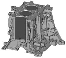
The analysed component is an in-line 4-cylinder diesel engine block (Fig. 1), which was produced by LPDC technology using experimental alloys 1 and 2, respectively. The casting was multiple-gated from the side of the crankshaft support to ensure good filling and proper feeding during solidification. A steel gauze filter was placed before the gating system after each casting. The weight of the machined Al alloy casting was about 21.1 kg.
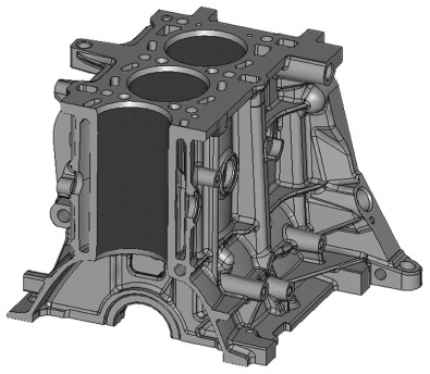 | Fig 1. CAD section of the in-line 4-cylinder diesel engine block analysed. |
The casting process was cyclic and began with the pressurization of the furnace. The excess pressure in the holding furnace forced the molten metal to fill the die cavity. The casting cycle was divided into the following steps: (1) Filling the riser tube in 10 s up to a pressure of 0.02 MPa; (2) Filling the die cavity up to two different final pressures (also called holding pressure), 0.035 and 0.05 MPa, respectively, at a constant pressure ramping time (35 s); thus, the pressurizing speed (P/t) was set up at 429 and 857 Pa/s, respectively. A rapid increase of the pressure up to the final value at constant pressure ramping time allows obtaining higher metal velocity at the gate vg according to the following equation[12]:
where P(t) is the pressure as function of time t, ρ is the density of molten metal, g is the gravitational constant, Ac is the cross-section area of the cavity, Af is the cross-section area of the crucible and At is the cross-section area of the riser tube. Higher metal flow velocity allows decreasing the filling time, which is defined as V/(Agvg), where V and Ag are the volume of die cavity and the gate area, respectively; (3) Holding the final pressure for 160 s to assist the feeding of solidification shrinkage in the die cavity. Therefore, the material solidifies under the holding pressure; (4) Discharging the pressure of the furnace in 5 s; (5) After the complete solidification, the side dies were opened, the top die was raised vertically and the casting was ejected (40 s); (6) The die was blown (30 s), the steel gauze filter and the sand cores were placed appropriately (95 s); (7) The die was closed and the cycle was restarted.
Typical cycle time was about 460 s. During solidification, circulating water at room temperature through internal channels in the dies was used to control the cooling rates of the casting and to stabilize the temperature of the dies in the range of (300-450) ± 5 ° C. The dies were made of AISI H11 tool steel.
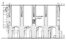
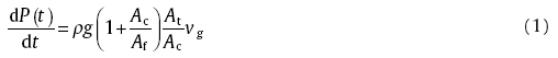
In order to evaluate the combined effect of pressure increase and Sr addition on the microstructure and casting defects, the cylinder blocks were sectioned transversally along the in-line cylinders. In general, the cylinder bridges show relatively thin thickness and are thermally and mechanically stressed regions. Therefore, the evaluation of microstructure is mandatory, as required by most of the customers' specifications[2]. Samples from the region indicated in Fig. 2 were drawn for metallographic investigations from three different castings, mechanically prepared to a 3 m finish with diamond paste and, finally, polished with a commercial fine silica slurry (Struers OP-S).
 | Fig 2. Locations where the specimens for metallographic investigations were drawn. |
To quantify the microstructural features, the image analysis was focused on the secondary dendrite arm spacing (SDAS) measured by the line intercept method, and on the size and aspect ratio of the eutectic Si particles. Size is defined as the equivalent circle diameter (d), and the aspect ratio (α ) is the ratio of the maximum to the minimum Ferets. To obtain a statistical average of the distribution, a series of at least 15 micrographs of each specimen was taken, and each measurement included more than 1000 particles. The secondary phases, such as Mg2Si particles, were excluded from the measurements.
Porosity was also studied in the same region, which corresponds to a hot spot in the casting. To obtain a statistical average, a series of 20 micrographs of each specimen were taken covering an area of about 6.6 mm × 2 mm. Quantitative metallographic techniques were also used to determine average pore area and roundness. The latter is defined as p2/(4π A), where p and A are perimeter and area of the pore, respectively.
The design of experiments (DOEs) is a statistical approach to the experimental investigation that allows analysing which process input has a significant impact on the process output. An analysis of variance (ANOVA) should be performed by considering the independent factors (inputs) and their interaction that influence the response (output). The ANOVA is a statistical methodology that enables to investigate and to model the relationship between the output and one or more input variables[13].
In the present study, a factorial ANOVA approach was implemented to investigate the effects of the Sr level and the pressurizing speed on the microstructural scale (SDAS), additionally the influence of the Sr level and the holding pressure on the amount of microporosity.
Each independent variable was analysed at two levels. The independent variables, along with their values at selected levels used in the statistical approach, are given in Table 2 and Table 3. With the aim of taking into account the highest degree of interaction, a full balanced factorial plan was implemented. Besides the Sr content and the pressure parameters as independent variables, their interaction was also considered and studied.
| Table 2 Independent variables selected in the DOE to study the effect on SDAS |
| Table 3 Independent variables selected in the DOE to study the effect on microporosity |
The following discusses the microstructural investigations included in the present study.
4.1.1. General microstructure
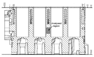
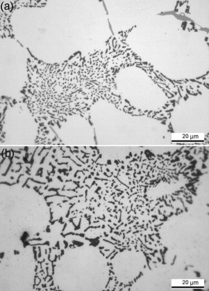
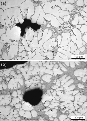
Typical microstructures of the analysed region drawn from the cylinder block are shown in Fig. 3, which refer to AlSi7Mg0.3 alloy after 170 ppm Sr addition and obtained with different pressure ramps. In general, the microstructure consists of a primary phase, α -Al solid solution, and an eutectic mixture of aluminium and silicon. The α -Al precipitates from the liquid as the primary phase in the form of dendrites. Intermetallic compounds, such as Fe- and Mg-rich intermetallics, are also observed. The Fe-bearing particles are present in the microstructure mainly in the form of needle-shaped β -Al5FeSi, even if some Chinese script α -Al15(Fe, Mn)3Si2 particles were detected. A high fraction of Mg-rich structures was detected in the form of Chinese script Mg2Si and π -Al8Si6Mg3Fe as products of binary eutectic reactions. In addition to these binary eutectic structures, some complex eutectic clusters were also observed on the polished sections, as formed from the ternary L → α -Al + Mg2Si + π -Al8Si6Mg3Fe and quaternary L → α -Al + π -Al8Si6Mg3Fe + Mg2Si + Si eutectic reactions, respectively.
 | Fig 3. Typical microstructures of 170 ppm Sr modified AlSi7Mg0.3 alloy (Alloy 2) obtained at (a) 429 and (b) 857 Pa/s pressurizing speed, respectively. |
4.1.2. Effect of pressure increase on SDAS
The scale of the microstructure was evaluated by means of SDAS measurements (see Table 4). Considering the relatively low heat extraction in the analysed region which is surrounded by sand cores, significant coarsening of the dendrite arms occurred during solidification as revealed from the coarse microstructural scale. While a lower filling pressure leads to a finer microstructure, the application of a higher pressure, which is further held during casting solidification, induces the formation of slightly greater dendrite arms, independent of the Sr level (see Fig. 3).
| Table 4 Average SDAS values measured under different experimental conditions (standard deviation in parentheses); cooling rate, calculated according to Eq. (2) is reported |
The range of cooling rates was estimated by secondary dendrite arm spacing, λ 2, which strictly depends on the cooling rate according to the empirical equation given below[14]

where R represents the mean cooling rate of the primary α -Al dendrites during solidification. The average SDAS values and the estimated cooling rates are listed in Table 4.
These results seem to be in contradiction with that reported in literature where it is stated how a significant refinement in the structure can be obtained in Al-Si foundry alloys by increasing the applied pressure[15, 16]. Even if these conclusions were drawn by applying squeeze casting technologies where the applied pressures are greater than those used in LPDC, the structure refinement is generally attributed to several factors. First, a significant increase in the cooling rate is obtained through improved contact between the casting and the die surface. The second factor is related to the thermodynamic nature of the applied pressure, which changes the melting point of metals and alloys. This relationship has been described with Clausius-Clapeyron equation[17]. For Al-Si binary alloys, the calculated increase in melting temperature has been estimated to be about 0.06 ° C/MPa[15]. Therefore, when pressure is applied to a liquid alloy at temperature just above its melting temperature, some degree of undercooling results, thus providing a greater amount of nuclei. Higher cooling rate, especially if coupled with a prompt undercooling, can cause significant refinement in the microstructure.
In the present work, the increase in the melting temperature has been calculated to be 0.0021 and 0.003 ° C for the holding pressures of 0.035 and 0.05 MPa, respectively, and therefore it is negligible. On the other hand, the highest pressure used here is definitely low, if compared to that applied in squeeze casting, for increasing the cooling rate by improving the contact between the casting and the sand cores placed in the die cavity.
The rapid increase of the pressure up to the final value at constant pressure ramping time (35 s) allows obtaining rapid filling speed of the metal inside the die cavity and thus lower filling time. This results in lower heat dissipation of the liquid close to the die/core surfaces. Therefore, the local cooling rate is reduced, which means that the local solidification time increases. The slower cooling rates obtained with steeper pressure ramp lead to significant coarsening in the microstructure if compared with that obtained by smoother pressure ramp.
Decreasing the filling time allows reducing the dissipation of melt superheat. It is reported how the grain size and the SDAS coarsen with increasing melt temperature, and the main cause of these phenomena is the decreasing cooling rate, which affects the nucleation and growth of grains[18]. In addition, the increased melt temperature deactivates available solidification sites, decreasing the frequency of grain nucleation.
To include the effect of melt superheat on the solidification time ts, Tiryaltioglu et al.[19] revised the Chvorinov Rule's and proposed the following equation:
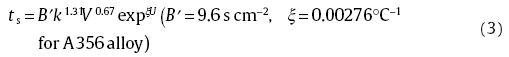
where B′ is a mould constant (s cm‒2), k is the shape factor which is defined as the ratio between the surface area of the sphere having the same volume as the casting and the surface area through which heat is lost by the casting, V is casting volume (cm3), ξ is an empirical constant (° C‒1), U is superheat (° C).
Therefore, the pouring temperature directly affects the solidification time of the alloy and thus the growth of the primary α -Al crystals.
On industrial casting production it is difficult to obtain high solidification rate throughout the casting, and therefore fine SDAS, for several reasons: (1) the complexity of the shape of cylinder blocks, having many cavities in close proximity; (2) the need for directional solidification to avoid casting macrodefects, and thus satisfactory quality in the final component; (3) efficient heat removal is possible only if close to the die walls; (4) the gating, and eventually riser, designs are influenced by the part geometry.
Several investigations have been published about the factors that influence SDAS and the relationship between SDAS and mechanical properties of Al alloy castings[20, 21, 22].
4.1.3. Effect of pressure increase on eutectic Si
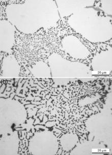
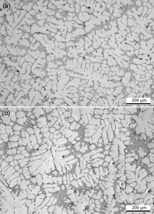
Due to Sr addition, the eutectic Si exhibits a fibrous morphology for the analysed pressure ramps with coarser particles by decreasing the filling time, i.e. increasing the pressurizing speed, at the same Sr level (Fig. 4). The size distributions of the eutectic Si particles were investigated and found to follow similar lognormal distributions, independent of the filling time. The hypothesis that the equivalent diameter of eutectic Si follows the lognormal distribution cannot be rejected with the Anderson-Darling test statistic for all four data sets. The fitted distributions are shown in Fig. 5(a). The coefficient of determination R2 was used to evaluate the quality of the fitting, and it is 0.99, suggesting a good agreement of the particle distribution with the lognormal distribution adopted.
 | Fig 4. Silicon crystals in the eutectic region of 170 ppm Sr modified AlSi7Mg0.3 alloy (Alloy 2) obtained at (a) 429 and (b) 857 Pa/s pressure, respectively. |
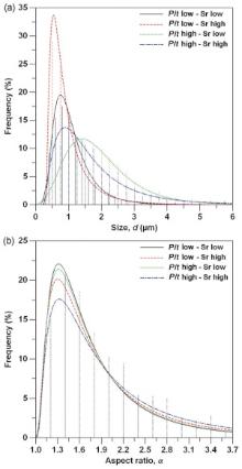
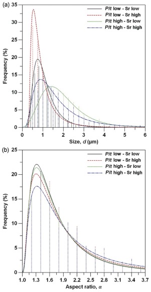 | Fig 5. Distributions of (a) equivalent diameter and (b) aspect ratio for eutectic Si particles estimated as function of the pressurizing speed and Sr levels. Lognormal fitting curves are drawn. |
By decreasing the cooling rate, that is, increasing the pressurizing speed, the distribution of the eutectic Si size becomes more spread for both the Sr levels analysed. The equivalent diameter of eutectic Si particles with the maximum frequency shifts to higher d values and the absolute value of the maximum frequency decreases. The average size, at 90 ppm Sr level (Alloy 1), moves from about 1.0 to 2.5 m for 429 and 857 Pa/s pressure increasing, respectively, and from about 0.7 to 1.7 m for the 170 ppm Sr modified alloy (Alloy 2). It can be established that increasing the filling speed, the microstructure is characterized by slightly coarser eutectic Si, while reducing the flow rate, the formation of a high number of fine Si particles is predominant.
The distribution of aspect ratio of eutectic Si particles also follows a lognormal distribution with a threshold, since the minimum value of α is 1. The threshold was here taken as 0.9, slightly below unity, so that the fit can allow the presence of particles with an aspect ratio of 1. The impact of the filling time, within the analysed range, on the morphology of eutectic Si is negligible. Therefore, an increase in the filling speed is related more to the size of the particles than to the aspect ratio, which is steady in the range of 1.9 to 2.1.
4.1.4. Effect of Sr addition on SDAS
The average SDAS values measured at different Sr levels are reported in Table 4 with the corresponding cooling rates calculated according to Eq. (2). In general, the microstructural scale decreases by increasing the Sr content in the alloy, independent of the applied pressure ramp. The lowest SDAS value is ~48 m when Sr level is 0.017 wt% and the pressure increase is set up at 429 Pa/s. Recently, Sui et al.[23] reported a general tendency of SDAS to gradually decrease and then increase by Sr addition in a gravity die cast AlSi12Cu4Ni2Mg0.8 alloy and the minimum value was measured at 0.02 wt% Sr. Fabrizi et al.[24] observed similar results for SDAS and grain size in a high-pressure die cast AlSi9Cu3(Fe) after 130 ppm Sr addition.
The size of the dendrites is, besides the cooling rate of solidification, dependent on the level of alloying elements present in the melt, even if this effect is not easily recognized due to the leading effect of the cooling rate. Rearranging Eq. (2) into a general form by taking into account the solute concentration, the secondary dendrite arm spacing can be expressed as[25]


where G is a constant (also called geometric factor) and M is expressed for a multicomponent alloy through:
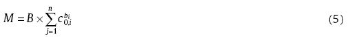
where B is a constant developing on the alloy and bi is the exponent of the concentration c0 of the i-th component.
During the solidification of primary phase, the alloying elements are not uniformly distributed between the solid and liquid phases. Excess of solute moves away from the solid-liquid interface into the melt increasing the solute content among the dendrite arms already formed. This supersaturation affects the constitutional undercooling at the solid-liquid interface, which is the driving force for the spacing adjustment mechanism in the region between the dendrite arms. The dendrite is able to branch sufficiently to reduce this undercooling to a very low value. It is also expected that the elements with a higher solubility in the Al melt are less effective in reducing the size of SDAS[26]. Higher concentration of alloying elements, e.g. Cu and Si as analysed by Sivarupan et al.[27], and Al-Si eutectic modifiers, e.g. Sb as reported by Boontein et al.[28], will cause the formation of finer dendrites with lower SDAS.
Therefore, the reduction in SDAS after the addition of a relatively low Sr level (~0.017 wt%) is believed to be the result of the constitutional undercooling promoted by Sr which segregates at the solidification interface due to very low partition coefficient in the Al-Sr system (< 0.0046 as calculated from Reference 29).
4.1.5. Effect of Sr addition on eutectic Si
The influence of Sr level on the eutectic Si size can be deduced from the lognormal distributions shown in Fig. 5(a). The distributions of the eutectic Si size become more spread by decreasing the Sr content, independent of the pressure parameters. However, the change of the eutectic Si size through variation of the Sr level is more evident at lower filling time (i.e. greater pressure increase), where slower cooling rates occur. The refining effect after Sr addition is almost comparable in the experimental conditions where the cooling rate is higher. Upon increasing the Sr content from 90 to 170 ppm, the average size of eutectic Si particles decreases about 29% at lower pressurizing speed, and about 32% at the highest pressure increase.
As it is possible to observe in Fig. 5(b), the variation in the aspect ratio of eutectic Si is negligible within the analysed Sr range. Therefore, in addition to the eutectic Si refinement, Sr is responsible for the morphological addition. However, in contrast to the refining mechanism, the applied pressure ramp seems not to compromise the Sr addition of eutectic Si morphology.
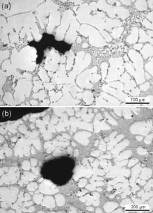
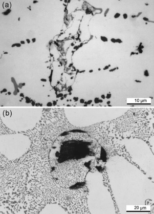
Fig. 6 shows the typical morphologies of various porosities in the polished surfaces of the samples. The pores have typical “ shrinkage” (Fig. 6(a)) or “ gas” (Fig. 6(b)) porosity aspects and were homogeneously distributed throughout the analysed section. While the former are coupled with a lack of interdendritic feeding during mushy zone solidification, gas porosity is the evolution of hydrogen due to a sudden decrease in hydrogen solubility during solidification[5]. Microporosity is a leading cause in the reduction of mechanical properties, particularly fatigue resistance[30], as well as a loss of pressure tightness, which is a key requirement in the cylinder blocks, especially in the space between the cylinders.
 | Fig 6. Typical pore morphology in the analysed region of the 90 ppm Sr modified AlSi7Mg0.3 alloy (Alloy 1): (a) shrinkage porosity and (b) gas porosity. The micrographs refer to a casting produced with 0.035 MPa holding pressure. |
To assess the efficiency of feeding for the different experimental conditions, the area fraction of porosity was measured in the analysed region of the cylinder blocks. The method based on the shape of pores is theoretically able to discriminate between the two forms of porosity. However, such a distinction was not considered to be relevant because most porosity is in any case assumed to be closely related to the presence of oxide films[31]. The difficulty of differentiating accurately between these defects was therefore avoided[29].
4.2.1. Effect of holding pressure on microporosity
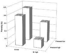
Fig. 7 summarizes the influence of holding pressure and Sr content on porosity in the castings. In general, the amount of porosity is low, therefore confirming LPDC as a useful foundry process for the production of Al blocks for high performance engines. Further, higher applied pressure generates castings with lower porosity content. In castings solidified under 0.035 MPa, the porosity fraction is in the range between 0.3% and 0.5%, and the components obtained with the highest holding pressure (0.05 MPa) show a porosity level between 0.1% and 0.4%. In the present work, the experimental results indicate that the applied pressure reduces the driving force for pore nucleation and growth.
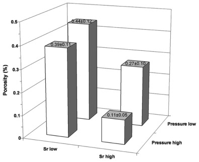 | Fig 7. Influence of holding pressure and Sr levels on the porosity in the analysed region of cylinder blocks. |
The average area and roundness of pores in the analysed region of three different castings for each experimental condition are given in Table 5. The pores in the castings produced with higher pressure are smaller and more rounded than the pores in the castings obtained at lower holding pressure.
| Table 5 Influence of holding pressure and Sr levels on the average size and roundness of pores |
The final applied pressure during casting solidification is aimed to feed and transport further material into the die cavity to compensate for the subsequent solidification shrinkage and thermal contraction, thus producing sound castings. In LPDC, the risers or feeders are limited with respect to sand casting or gravity die casting. Contrary to high-pressure die casting or squeeze casting where the intensification pressures are greater (up to ~120 MPa), the pressure applied in LPDC is low enough to prevent the evolution of dissolved hydrogen or to effectively compress any entrapped air.
Pore growth is governed by Eq. (6), which represents a balance between the pressures that promote and oppose pore formation[32]:

where Pg is the equilibrium pressure of dissolved gases, Ps is the pressure drop due to solidification shrinkage, Papp is the applied pressure, PH is the pressure due to metallostatic head, and Ps-t is the pressure due to pore-liquid surface tension. Thus, the pore formation can occur when the sum of the pressures referred to solidification shrinkage and hydrogen rejection is larger than the combined effects of applied pressure, metallostatic head and surface tension. For a wetting liquid, Ps-t can be expressed as 2γ /r where γ is the surface tension and r is the pore radius [32]. Therefore, the pore size can be calculated as follows:

The size and amount of porosity is expected to be inversely proportional to the applied holding pressure.
On the other hand, it can be reasoned that impurities may affect porosity formation. They may alter the surface tension, so the term Ps-t, and the stability of the protective oxide layer, affecting the term Pg; they may act as active nucleate site for pores allowing pore formation at a lower gas pressure, Pg, or hydrostatic shrinkage pressure, Ps, than would otherwise be the case; they may affect the evolution of the microstructure during solidification, altering in this manner the term Ps.
In the present work, density measurements carried out by reduced-pressure testing revealed a strict range of density values, 2.63-2.65 g/cm3. Therefore, it can be assumed that the number of heterogeneous pore nucleation sites in the liquid bath inside the holding furnace remained constant over the entire experimental campaign.
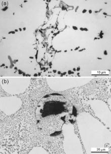
As the pressurizing speed increases, the flow of metal inside the die cavity can be more turbulent, eventually leading to the entrainment of inclusions and gases, and an increase in porosity. Fig. 8 shows the typical filling-related defects, such as oxide films and cold shots, as revealed in the castings produced with greater pressure increase. As evidenced by Liu et al.[12], the gate velocity increases with the effective pressure under higher pressurizing speed, leading to gate velocities greater than critical value (0.5 m/s)[31]. This leads to greater turbulence which is the main cause of oxide film entrainment and formation of cold shots. However, the application of higher pressure may eventually prevent the potential increase in porosity by restricting pore growth[33]. It is clear from Eq. (7) that the size of the pores, and hence the amount of porosity, is not linearly proportional to the applied pressure.
 | Fig 8. Typical filling-related defects, (a) oxide films and (b) cold shot, observed in the castings produced with higher pressurizing speed. |
4.2.2. Effect of Sr addition on microporosity
The effect of Sr on the amount of porosity can be observed in Fig. 7. Contrary to expectations derived from the literature, the average porosity decreases by increasing Sr content from 90 up to 170 ppm in the alloy, and this behaviour seems to be independent of the applied holding pressure.
Strontium addition is generally associated with an increase in porosity, especially above that of the unmodified alloy, and also a redistribution of porosity from macroscopic shrinkage porosity to well-dispersed microporosity[5]. Further, higher amount of porosity was generally detected by increasing the Sr content in the liquid bath[34]. Recently, Dinnis et al.[35] demonstrated how a different distribution of eutectic solid throughout the dendritic network due to changes in nucleation and growth modes can affect feeding and porosity formation. Gradually increasing the Sr content, the eutectic grains begin to nucleate and grow away from existing primary α -Al dendrites, independent of them, with a relatively smooth solidification front[36, 37]. This mechanism may lead to an increase in porosity because the growth of the eutectic grains can obstruct feed paths causing a decrease in permeability and feeding efficiency.
In the present work, the porosity differences in the Sr-containing AlSi7Mg0.3 engine blocks can be related to the eutectic solidification mode by considering the ability of the riser tube in the LPDC machine through the runners and gating system to supply feed metal to the analysed region between the cylinders, which represents a hot spot in the casting. The multiple runners connected to the riser tube and the ingates solidify early and cannot supply feed metal to the region between the cylinders. After the runners' solidification, the hot spot of the engine block acts as a riser for the casting. In high Sr-modified alloy (Alloy 2), the low permeability of thesolidifying microstructure, due to independent nucleation of eutectic grains, reduces the flow of metal out of the hot spot to feed the rest of the casting. In contrast, in the low Sr modified alloy (Alloy 1), the relatively permeable microstructure enables liquid to flow from the hot spot to feed the remainder of the casting. Therefore, the porosity in the analysed region is lower by increasing the Sr level from 90 up to 170 ppm in the AlSi7Mg0.3 alloy.
The average area and roundness of pores measured at different Sr contents are listed in Table 5. Pores are smaller and more rounded by Sr increasing, independent of the applied pressure. This behaviour seems to not be associated with the dissolved hydrogen in the bath. The reduced-pressure test, which has been shown to be a reasonable and useful method for hydrogen measurement[38], revealed almost a steady-state value during the experiments. Upon increasing the Sr level, the pores become more rounded due to the progressive change in the morphology of the solidification front. Dahle et al.[37] explained how the eutectic grains, nucleatingindependently of the α -Al dendrites, grow with a relatively smooth solidification front because the fibrous morphology of the eutectic silicon does not grow ahead of the eutectic aluminium.
The analysis of the data by means of ANOVA revealed a complete and exhaustive evaluation of the relationship between the independent variables, such as pressure parameters and Sr content, and the dependent variables, i.e. SDAS and amount of porosity, within the experimental conditions. Fig. 9 and Fig. 10 show the results of SDAS values and amount of porosity, in terms of main effect diagrams and Pareto charts. Further, Table 6 and Table 7 summarize the results of ANOVA for SDAS and porosity. As generally reported in the ANOVA tables[13], the number of degrees of freedom from each source (DF), the sum of squares (SS), the mean squares (MS), the results of Fisher test (F-value) and the p-values are shown. Furthermore, both the sequential (Seq SS) and the adjusted sums (Adj SS) and mean (Adj MS) of squares are also indicated. A detailed description of the statistical method used was given elsewhere [13].
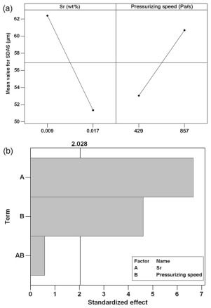 | Fig 9. (a) Main effects plot displaying the influence of Sr content and pressurizing speed on SDAS; (b) Pareto chart evaluates the significant variables and their possible interactions (p-value of 0.05 is drawn as a reference line). |
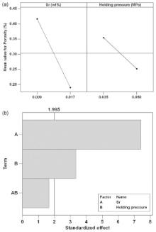
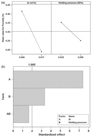 | Fig 10. (a) Main effects plot displaying the influence of Sr content and holding pressure on the amount of porosity; (b) Pareto chart evaluates the significant variables and their possible interactions (p-value of 0.05 is drawn as a reference line). |
| Table 6 Analysis of variance for SDAS (coded units) |
| Table 7 Analysis of variance for porosity (coded units) |
Fig. 9 and Fig. 10 show the relative power of each factor, or interaction, to affect the variation in the microstructural scale or porosity level. At the studied levels, the variable most significantly affecting the analysed properties is the Sr content in the AlSi7Mg0.3 alloy. At higher level, while Sr tends to decrease both SDAS and porosity, the effects of the pressure parameters depend on the specific characteristic. Upon increasing the pressurizing speed during die cavity filling, the SDAS value increases; on the other hand, the porosity decreases by increasing the holding pressure. The effects of the relationships among the factors, i.e. Sr∙ Pressurizing speed and Sr∙ Holding pressure, appear statistically insignificant, with a p-value higher than 0.05 for both the features analysed (see Fig. 9 and Fig. 10(b)).
On the basis of the significance level provided by the analysis of variance, a linear regression model can be developed describing the relationship between the response and the predictor variables. The reliability of the model is based on the coefficient of determination, R2, which measures the quality of the least-squares fitting to the experimental data. In the considered range of experimental conditions, the size of SDAS and the amount of porosity can be described by the following semi-empirical equations:
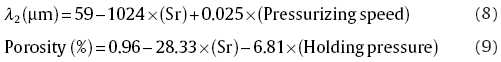
where Sr is in wt%, Pressurizing speed is in Pa/s and Holding pressure is in MPa. In order to verify the reliability of the regression models of Eqs. (8) and (9), the experimental Sr contents (see Table 1) and the experimental pressure parameters during LPDC were used to predict the SDAS and the level of porosity. These results were compared with the measured ones to describe the quality of the developed models by means of R2 values, which are 0.99 and 0.95 for the average SDAS value and porosity, respectively.
(1)The increase in the pressurizing speed reduces the filling time and induces the formation of slightly greater dendrite arms, independent of the Sr level.
(2)Coarsening of the eutectic Si particles is observed by increasing the pressurizing speed.
(3)The microstructural scale decreases by increasing the Sr content in the alloy, independent of the applied pressure ramp.
(4)Upon increasing the Sr level in the alloy, the average size of eutectic Si decreases more at lower filling time, which is obtained by increasing the pressurizing speed.
(5)The impact of both applied pressure and Sr content, within the analysed conditions, on the morphology of eutectic Si is negligible.
(6)Higher holding pressure and Sr content generate cylinder bridges with lower porosity content.
(7)As the pressurizing speed increases, the flow of metal inside the die cavity can be more turbulent, leading to the formation of oxide films and cold shots.
(8)In the considered experimental conditions, the average size of SDAS and the amount of porosity can be significantly described by a regression model that considers the concentration of Sr and the pressure parameters applied during LPDC.
The authors acknowledge Dr. R. Molina and Dr. M. Badiali from Teksid Aluminum Spa (Carmagnola, Italy) for the support to this research, and thank Dr. A. Guglielmi for the experimental contribution to this work.
| [1] |
|
| [2] |
|
| [3] |
|
| [4] |
|
| [5] |
|
| [6] |
|
| [7] |
|
| [8] |
|
| [9] |
|
| [10] |
|
| [11] |
|
| [12] |
|
| [13] |
|
| [14] |
|
| [15] |
|
| [16] |
|
| [17] |
|
| [18] |
|
| [19] |
|
| [20] |
|
| [21] |
|
| [22] |
|
| [23] |
|
| [24] |
|
| [25] |
|
| [26] |
|
| [27] |
|
| [28] |
|
| [29] |
|
| [30] |
|
| [31] |
|
| [32] |
|
| [33] |
|
| [34] |
|
| [35] |
|
| [36] |
|
| [37] |
|
| [38] |
|